
Related Manuals for Tsino Dynatron CoolDrive Series

Summary of Contents for Tsino Dynatron CoolDrive Series
- Page 1 CoolDrive Series Smart 7 Servo Drive User Manual Model: CDS7S EtherCAT interface Document Version: R1...
- Page 2 Safety Instructions Safety Instructions Warning signs This manual uses the following identification terms to explain what need to be followed in order to prevent personal injury or death and equipment damages. These identification terms distinguish the degree of harm and damages that can occur during misuse.
- Page 3 Safety Instructions The following precautions must be followed to ensure safety Overall Precautions Danger For your safe use of the product, carefully read this manual. Keep this manual in a safe place and ensure that it is delivered to the end user. ...
- Page 4 Safety Instructions Note Use a noise filter, etc. to reduce the effects of electromagnetic interference. Otherwise, it will cause electromagnetic interference to electronic devices used near the servo drive. Use specified combinations of the servo drive and servo motor. ...
- Page 5 Safety Instructions Precautions when keeping the product Note Do not overload this product (follow the instructions). Otherwise it may cause injury or malfunction. Keep and install the product in places: • Without direct sunlight • Where the ambient temperature does not exceed the limits allowed for running this product •...
- Page 6 Safety Instructions Installation precautions: Note Install the servo drive in a position with sufficient bearing capacity according to the technical data. Install the servo drive, servo motor, regenerative resistor and dynamic brake resistor on non-combustible items. Installing directly on or near combustible items may cause a fire. ...
- Page 7 Safety Instructions Precautions for wiring Danger Do not change the wiring when the power is on. Otherwise it may result in electric shock or injury. Warning Wiring and wiring inspections need to be done by professional technicians. Otherwise it may cause electric shock or malfunction.
- Page 8 Safety Instructions Note circuit. Install a safety device such as a circuit breaker for wiring to prevent short-circuiting of external wiring. Failure to do so may result in fire or malfunction. Securely tighten the fixing screws and locking mechanism of the cable connector. If it is not tightened sufficiently, the cable connector may come off during operation.
- Page 9 Safety Instructions Note For the gain adjustment during system startup, check the torque waveform and speed waveform with a measuring instrument to make sure that there is no vibration. Vibrations due to high gains can cause premature damages to the servo motor. ...
- Page 10 Safety Instructions Precautions during maintenance and inspection Danger Do not change the wiring when the power is on. Otherwise it may result in electric shock or injury. Warning Wiring and wiring inspections need to be done by professional technicians. Otherwise it may cause electric shock or malfunction.
- Page 11 Safety Instructions Precautions for handling exceptions Danger When the safety devices (wiring circuit breakers and fuses) on the power cord are in action, switch on the servo drive only after finding out and eliminating the events that result in their action. In addition, replace or repair the servo drive and check the wiring to effectively eliminate the events that result in the actions of safety devices.
- Page 12 Safety Instructions Precautions for discarding Note Follow common industrial waste disposal procedures when discarding this product. However, applicable laws of each country shall prevail if such procedures conflict with these laws. If necessary, take measures such as labeling and attaching notices to the final product. ...
-
Page 13: Table Of Contents
Contents Safety Instructions----------------------------------------------------------------- 1 Contents 1 Chapter 1 Preface ---------------------------------------------------------------- 8 Overview ----------------------------------------------------------------------------------------------- 8 1.1.1 Chapters -------------------------------------------------------------------------------------------------------------- 8 1.1.2 Identification Description ------------------------------------------------------------------------------------------ 9 1.1.3 Parameter Description --------------------------------------------------------------------------------------------- 9 Data Plate -------------------------------------------------------------------------------------------- 10 Model identification-------------------------------------------------------------------------------- 11 Specifications ---------------------------------------------------------------------------------------- 12 1.4.1 Universal Specifications of (Standard) CDS7S ---------------------------------------------------------------- 12 1.4.2 Technical Specifications of (Standard) CDS7S ---------------------------------------------------------------- 14 Name of Each Part of the Product --------------------------------------------------------------- 15... - Page 14 Precautions for Wiring ----------------------------------------------------------------------------- 29 3.1.1 Safety Requirements---------------------------------------------------------------------------------------------- 29 3.1.2 System Wiring Requirements ----------------------------------------------------------------------------------- 30 System Wiring Diagram ---------------------------------------------------------------------------- 31 Power Supply Wiring ------------------------------------------------------------------------------- 32 3.3.1 Ports and Functions ----------------------------------------------------------------------------------------------- 32 3.3.2 Power Supply Wiring Diagram ---------------------------------------------------------------------------------- 34 3.3.3 Precautions for Power Supply Wiring -------------------------------------------------------------------------- 37 Motor Wiring ---------------------------------------------------------------------------------------- 38 3.4.1 Ports and Functions ----------------------------------------------------------------------------------------------- 38...
- Page 15 Position Control Settings -------------------------------------------------------------------------- 82 Velocity Control Setting --------------------------------------------------------------------------- 87 Torque Control Settings --------------------------------------------------------------------------- 91 Servo Enabling Setting ----------------------------------------------------------------------------- 93 Setting of Stop Function --------------------------------------------------------------------------- 95 4.10 EtherCAT Communication Setting -------------------------------------------------------------- 106 4.11 CiA402 Setting -------------------------------------------------------------------------------------- 107 Chapter 5 Running------------------------------------------------------------- 109 Precautions before running ---------------------------------------------------------------------- 109 Magnetic Pole Phase Angle Detection --------------------------------------------------------- 109 5.2.1...
- Page 16 Safety Instructions --------------------------------------------------------------------------------- 134 7.2.1 Position limit setting --------------------------------------------------------------------------------------------- 134 7.2.2 Torque limit setting ---------------------------------------------------------------------------------------------- 134 7.2.3 Following error limit setting ------------------------------------------------------------------------------------ 134 Current Loop Setting ------------------------------------------------------------------------------ 135 7.3.1 Overview ----------------------------------------------------------------------------------------------------------- 135 7.3.2 Associated parameters ------------------------------------------------------------------------------------------ 135 7.3.3 How to use -------------------------------------------------------------------------------------------------------- 136 System parameter identification ---------------------------------------------------------------- 137 7.4.1 Overview ----------------------------------------------------------------------------------------------------------- 137...
- Page 17 7.9.1 Overview ----------------------------------------------------------------------------------------------------------- 156 7.9.2 Velocity feedforward -------------------------------------------------------------------------------------------- 156 7.9.3 Acceleration feedforward--------------------------------------------------------------------------------------- 157 7.9.4 Acceleration feedforward exceptions correction ----------------------------------------------------------- 158 7.9.5 No Position Deviation Control --------------------------------------------------------------------------------- 159 7.10 Lowpass filters-------------------------------------------------------------------------------------- 160 7.10.1 Overview ----------------------------------------------------------------------------------------------------------- 160 7.10.2 Associated parameters ------------------------------------------------------------------------------------------ 161 7.10.3 How to use -------------------------------------------------------------------------------------------------------- 162 7.11 Vibration suppression ----------------------------------------------------------------------------- 163...
- Page 18 8.4.2 Associated parameters ------------------------------------------------------------------------------------------ 180 8.4.3 How to use -------------------------------------------------------------------------------------------------------- 181 Field weakening control mode ------------------------------------------------------------------ 187 8.5.1 Overview ----------------------------------------------------------------------------------------------------------- 187 8.5.2 Associated parameters ------------------------------------------------------------------------------------------ 187 8.5.3 How to use -------------------------------------------------------------------------------------------------------- 188 Position comparison output --------------------------------------------------------------------- 189 8.6.1 Overview ----------------------------------------------------------------------------------------------------------- 189 8.6.2 Associated parameters ------------------------------------------------------------------------------------------ 189 8.6.3...
- Page 19 9.1.9 Panel monitoring - current alarm or warning --------------------------------------------------------------- 212 Debugging software monitoring ---------------------------------------------------------------- 213 9.2.1 Overview ----------------------------------------------------------------------------------------------------------- 213 9.2.2 Debugging software monitoring - device information ----------------------------------------------------- 213 9.2.3 Debug software monitoring - state information ------------------------------------------------------------ 214 9.2.4 Debugging software monitoring - operating data ---------------------------------------------------------- 215 9.2.5 Debugging software monitoring - Alarm and warning information ------------------------------------- 219 9.2.6...
-
Page 20: Chapter 1 Preface
Preface Chapter 1 Preface Overview 1.1.1 Chapters The main contents of each chapter of this manual are described below. Number Chapter name Overview of contents Introduces the main methods of using this manual, product specifications and models, Preface and related standards and certifications Installation Introduces the dimensions and installation requirements of each servo drive model. -
Page 21: Identification Description
Preface 1.1.2 Identification Description The following signs are designed in this manual to help readers distinguish between different types of texts. These signs alert users to what they need to attend to when using the servo drive These signs indicate which operations or actions are prohibited to prevent equipment failure or injury. -
Page 22: Data Plate
Preface Data Plate This section describes the information contained in the CDS7 series servo drive data plate. Product QR code Product model Serial number Input and output voltage Input and output frequency Rated power of Number of input and output phases adapter motor Input and output rated curren IP code... -
Page 23: Model Identification
Preface Model identification This section describes the naming rules for CDS7S servo drive models. CDS7S–1D0 A–SA 0–E 0 0–A00 Number Item Symbol Description ① Drive series CDS7S Standard, position/speed/torque control 1 Arms 2 Arms 3 Arms 5 Arms ② Rated current 7 Arms 10 Arms 15 Arms... -
Page 24: Specifications
Preface Note 1: CDS7S only supports single encoder. When the first encoder port selects "SA" or "SC", the second encoder port must select "0". Note 2: Some protocols are under development. "SA" supports protocol encoders such as TAMAGAWA, and "SC" supports Nikon / HiperfaceDSL (4-wire) /Biss-C/SSI/EnDat2.2 and other protocol encoders, consult the corresponding vendor for specific information. - Page 25 Preface Models Regenerative braking resistor Built-in regenerative braking resistor — 50/50 20/100 10/100 (Ω/W) Minimum allowable external regenerative braking resistance (Ω) Cooling mode Fan forced cooling Dynamic brake Built-in Usage environment Ambient temperature, relative No reduced rated power in 0°C~45°C, lower rated power in 45°C~55°C; 20%~85% RH (No humidity of usage environment condensation) Ambient...
-
Page 26: Technical Specifications Of (Standard) Cds7S
Preface 1.4.2 Technical Specifications of (Standard) CDS7S Control method (rotary motor) CDS7S Position control, speed control, torque control First encoder Note 1 Serial asynchronous encoder Supports absolute value encoder protocol: Tamagawa, etc. Serial synchronous encoder Developing Second encoder ABZ incremental encoder A, B, Z signals Hiperface encoder Sine / cosine differential input signal... -
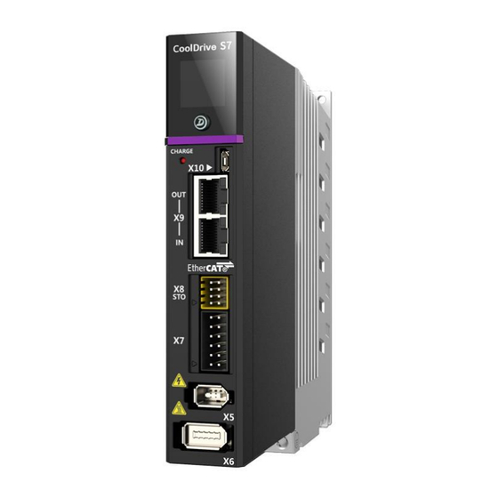
Page 27: Name Of Each Part Of The Product
Preface Name of Each Part of the Product This section describes the names and functions of the main components of the CDS7 servo drives. Number Name Main functions Configuration Used for connecting with three-phase or single-phase Standard Power supply input port (X1) AC power supplies to provide power supply input for Configuration servo drives... - Page 28 Preface The content described in this section contains all the parts and functions supported by the CDS7 servo drives. Some of these parts and functions are optional, so when referring to this section, take into account the model you actually selected. T1-T4 models of CDS7 servo drives are shown below in plan view, and the numbers in the figure correspond to the numbers in the table.
- Page 29 Preface T2 model...
- Page 30 Preface T3 model...
- Page 31 Preface T4 model...
-
Page 32: Standards And Certification
Preface Standards and Certification CDS7S drives meet the following standards: EU CE Standard Certification Directive Directive name Applicable standards mark EMC directive 2004/30/EU EN 61800-3: 2014+A1: 2012 voltage 2014/35/EU EN 61800-5-1: 2007 directive Safety standards Safety Equipment models Standards standards IEC 61508-1... -
Page 33: Chapter 2 Installation
Installation Chapter 2 Installation Precautions Follow the following requirements during installation: Warning Explosive or flammable gases Do not use the servo drive in an environment with explosive gas or flammable gases; If the components such as relays, contactors, and regenerative resistors in the cabinet generate produce sparks, they can become a source of fire and cause fire or explosion. -
Page 34: Inspection
Installation Note measures such as installing a filter in the front of the drive, optimizing the wiring, and reducing interference from the interference source. Inspection After the product is delivered to you, check the following: Is there any damaged or missing packaging during product transportation? ... -
Page 35: Dimensions
Installation Dimensions 2.3.1 T1 model dimensions Unit [mm] Contact us if you want more information of unspecified dimensions in the drawings... -
Page 36: T2 Model Dimensions
Installation 2.3.2 T2 model dimensions Unit [mm] Contact us if you want more information of unspecified dimensions in the drawings... -
Page 37: T3 Model Dimensions
Installation 2.3.3 T3 model dimensions Unit [mm] Contact us if you want more information of unspecified dimensions in the drawings... -
Page 38: T4 Model Dimensions
Installation 2.3.4 T4 model dimensions Unit [mm] Contact us if you want more information of unspecified dimensions in the drawings... -
Page 39: Installation Direction And Space Requirements
Installation Installation Direction and Space Requirements 2.4.1 Drive Installation Direction The recommended installation direction of the drive is shown in the following figure: Install backplane 安装背板 气流方向 Direction of airflow Since the heat generated by the servo drive is radiated from the bottom to the top, in order to ensure the stable performance of this device, it is usually required to be installed vertically, that is, to ensure that the airflow direction of the drive's own forced air cooling is from bottom to top. -
Page 40: Drive Installation Space Requirements
Installation 2.4.2 Drive Installation Space Requirements When installing the drive in a cabinet, ensure that the following spaces are left around: 40mm以上 40mm以上 More than 40mm More than 40mm More than 30mm以上 100mm以上 30mm More than (推荐) 或根据实际布 100mm 线情况决定 Ventilation 40mm以上... -
Page 41: Chapter 3 Wiring
Wiring Chapter 3 Wiring Precautions for Wiring 3.1.1 Safety Requirements The following requirements should be strictly followed when wiring. Warning Do not touch the internal components of the servo drive; otherwise, there are chances of electric shock. When the servo is powered on, no one is allowed to enter the range of its mechanical movement to prevent any possible personal injury or deaths. -
Page 42: System Wiring Requirements
Wiring 3.1.2 System Wiring Requirements Pay attention to the following when wiring the main circuit: It is recommended to use the twisted-pair wire or multi-core twisted-pair overall shielded wire as the input/output signal line and encoder cable. Do not press or damage the cable. ... -
Page 43: System Wiring Diagram
Wiring System Wiring Diagram External regenerative When using the built-in resistor Debug PC regenerative resistor MicroUSB (only T2、T3 models support) AC power single-phase 200~240V Next Drive EtherCAT OUT Controller EtherCAT IN AC power Three-phase200~240V Single-phase power input (only partial models support) AC power Only for models with safety brake function Single-phase200~240V... -
Page 44: Power Supply Wiring
Wiring Power Supply Wiring This chapter describes the wiring of the servo drive power circuit, including how to wire the power supply, control power, DC bus and regeneration braking circuits. 3.3.1 Ports and Functions The port connector illustrations and pin definitions related to power supply wiring are shown in the following table. Connector illustrations and pin definitions Port name T1, T2 models... - Page 45 Wiring Three-phase AC 220 V power supply input Port name Pin symbol Specifications and parameters Power supply input port (X1) L1, L2, L3 Three-phase AC 200V~240V, -15%~+10%; 50/60 Hz L1C, L2C Single-phase AC 220 V, ± 15%; 50/60 Hz When using the built-in regenerative resistor, short circuit interfaces B Control power and regenerative and RB, and do not use interface P.
-
Page 46: Power Supply Wiring Diagram
Wiring 3.3.2 Power Supply Wiring Diagram Three-phase AC 220 V power supply input External regenerative resistor When using the built-in regenerative resistor (only T2、T3 models support) AC power single-phase 200~240V AC power Three-phase 200~240V No connection CDS7S... - Page 47 Wiring Single-phase AC 220 V power supply input (supported by T1, T2 models) External regenerative resistor When using the built-in regenerative resistor (only T2、T3 models support) AC power single-phase 200~240V AC power Single-phase 200~240V No connection CDS7S...
- Page 48 Wiring DC power supply input (optional) External regenerative resistor When using the built-in regenerative resistor (only T2、T3 models support) AC power single-phase 200~240V Note: When connecting to the X4 port, the X1 port is forbidden to be wired, otherwise the drive will be damaged. DC power supply 310V CDS7S...
-
Page 49: Precautions For Power Supply Wiring
Wiring 3.3.3 Precautions for Power Supply Wiring Cable Type Selection Examples of the relationship between the nominal cross-sectional area of cable and the permissible current are shown in the following table: Nominal cross-sectional Allowable current (Unit: A) at different ambient temperatures area / mm 30°C 40°C... -
Page 50: Motor Wiring
Wiring Motor Wiring This chapter introduces the wiring related to the servo drive and the motor, mainly including the motor power line, the motor brake control circuit, the motor temperature detection circuit and the wiring methods of different types of encoders. 3.4.1 Ports and Functions The diagram and pin definition of each port connector related to the motor wiring are shown in the following table. - Page 51 Wiring Motor power output Port name Pin symbol Functions Motor output port (X2) U, V, W Connect with the three-phase power line of servo motor Ground terminal Connect with the motor housing Motor brake and temperature detection port (connecting with safety brake control circuit) Port name Signal name Functions...
- Page 52 Wiring First encoder port (connecting with synchronous serial communication encoder) Port name Signal name Functions VCC1 Encoder Power +5V Encoder Power 0V CLK+ Clock signal + First encoder Port (X5) CLK- Clock signal - DATA+ Serial data + DATA- Serial data- Housing Shielding...
-
Page 53: Motor Wiring Diagram
Wiring Second encoder port (connecting with asynchronous serial communication encoder) Port name Signal name Functions VCC2 Encoder Power +5V Encoder Power 0V DATA+ Serial data + DATA- Serial data- Do not use Second encoder port (X6) Do not use Do not use Do not use Do not use... - Page 54 Wiring Only for models with safety brake function +24V DC24V 24VGND MBK- MBK+ Motor brake First encoder wiring (connecting with asynchronous serial communication encoder) Asynchronous serial CDS7S communication encoder wiring VCC1 DATA+ DATA- shield First encoder wiring (connecting with synchronous serial communication encoder) Synchronous serial CDS7S communication encoder wiring...
- Page 55 Wiring Second encoder wiring (connecting with Hiperface encoder) CDS7S Hiperface encoder wiring VCC2 DATA+ DATA- SIN+ SIN- COS+ COS- shield Second encoder wiring (connecting with ABZ / UVW wire-saving incremental encoder) ABZ incremental CDS7S encoder wiring VCC2 shield The symbol indicates that the wires need to be a twisted pair wires...
-
Page 56: Precautions For Motor Wiring
Wiring 3.4.3 Precautions for Motor Wiring When wiring the power line of the motor, select a suitable cable diameter according to the working current of the selected motor. Refer to the diameter reference value in section 3.3.3 for more details; ... -
Page 57: Ethercat Wiring
Wiring EtherCAT Wiring 3.5.1 EtherCAT Introduction EtherCAT Overview EtherCAT is short for Ethernet for Control Automation Technology. EtherCAT is open network communication between primary and secondary stations for real-time Ethernet. EtherCAT is developed by Beckhoff Automation GmbH, and managed by ETG (EtherCAT Technology Group). -
Page 58: Port Symbols And Functions
Wiring 3.5.2 Port Symbols and Functions EtherCAT Communication Wiring Port name Signal name Functions symbol DP_PHY0_ TX+ Send data + DP_PHY0_ TX- Send data - EtherCAT communication DP_PHY0_ RX+ Receive data + port (X9) —— —— —— —— DP_PHY0_ RX+ Receive data + ——... -
Page 59: Precautions For Ethercat Wiring
Wiring This wiring diagram is an example of a typical linear topology. If other network topologies are used, refer to the relevant EtherCAT documentation and networking equipment specifications. 3.5.4 Precautions for EtherCAT Wiring Choose CAT6A network cable with shielding layer and RJ-45 plug with metal shielding layer. ... -
Page 60: I/O Wiring
Wiring I/O Wiring 3.6.1 Port Symbols and Functions I/O port wiring Port name Pin symbol Signal name Functions DI-COM Digital signal input common terminal HDI1 Digital Signal Input 1 (High Speed) HDI2 Digital Signal Input 2 (High Speed) I/O port (X7) Digital Signal Input 3 Digital Signal Input 4 Digital Signal Input 5... - Page 61 Wiring DI High level CDS7S Wiring when DI is active low CDS7S DI Low level In DI wiring, in order to ensure the primary current of the photocoupler, the input power voltage should be greater than 12V.
- Page 62 Wiring DO Wiring CDS7S Controller Among them, DO3 can be used to control the motor holding brake. When in use, it is prohibited to connect DO3 directly with the motor holding brake. An intermediate relay must be used for this purpose, as shown in the figure below. DO3 control motor brake CDS7S DC24V...
-
Page 63: Sto Wiring
Wiring STO Wiring 3.7.1 Port Symbols and Functions STO Wiring Port name Pin symbol Signal name Functions Do not use Do not use STO Port (X8) STOM Safety Torque Off function Monitor + STOM-RET Safety Torque Off function Monitor- STO2 Safety Torque Off function signal input 2+ STO2-RET... - Page 64 Wiring Wiring when not using the STO function CDS7S When the STO function is enabled, do not use the NC1 and NC2 interfaces. When the STO function is disabled, short circuit the NC1 and NC2 interfaces.
-
Page 65: Chapter 4 Settings
Settings Chapter 4 Settings Parameter overview 4.1.1 Parameter Description: The servo parameters are divided into the following 4 categories. Type Description Function For such parameters, sub-options can be selected from the drop-down menu. Sub-options cannot selection coexist. Only one sub-option can be selected at a time parameters selection Such parameters can be selected by ticking ✔... - Page 66 Settings Numerical setting parameters: values of these parameters can be directly modified Read-only parameters: No information can be modified Ways that parameters come into force are divided into the following two types: Ways of coming Description into force The drive needs to be restarted for the modified parameters to take effect. This type of parameter can Restart only [set saved value].
-
Page 67: Parameter Setting Method
Settings 4.1.2 Parameter setting method Parameters can be set by using debugging software or through an upper computer. When using the upper computer for parameter setting, the control right should be set to the EtherCAT master first, and then the parameters should be configured as PDO and then modified, or modified in SDO. - Page 68 Settings Change the parameters that need to be modified. Click [Set Save Value] and close the window. If you modify the parameters that restart the drive to take effect, the main interface will give the following prompt. The parameters will take effect after restarting the drive.
-
Page 69: Parameters Return To Factory Settings
Settings 4.1.3 Parameters Return to Factory Settings This section describes operations when the parameters are restored to factory settings. There are two cases when the parameters are restored to the factory settings: Current servo parameter value restored to default value It means restoring only the current value of the current parameter version to the default value of the current parameter version. - Page 70 Settings Select [Restore default values of current servo parameters] / [Initialize all information of servo parameters] and click [OK]. Click [Yes] in the pop-up window. When prompted that factory settings are restored successfully, click [OK] to restart the drive for the factory settings to take effect.
-
Page 71: Drive Parameter Setting
Settings Drive Parameter Setting Set the following drive parameters correctly. Sub-ind Default Index Name Unit Setting range effective Period value External Regeneration 0x20D4 1~2147483647 Restart Resistor Pulse Energy Sub-ind Default Index Name Unit Setting range effective Period value Power Stage 0x2130 —... - Page 72 Settings Sub-ind Default Index Name Unit Setting range effective Period value External Regeneration 0x2132 1~65535 Restart Resistor Value Set the resistance value of the external energy consumption braking resistor. The resistance should be consistent with the actual braking resistor parameter. Sub-ind Default Index...
- Page 73 Settings Sub-ind Default Index Name Unit Setting range effective Period value The parameter is read-only and cannot be modified. Sub-ind Default Index Name Unit Setting range effective Period value Over voltage 0x2135 protection threshold 0~4294967295 Restart value The parameter is read-only and cannot be modified. Sub-ind Default Index...
- Page 74 Settings Sub-ind Default Index Name Unit Setting range effective Period value Drive Overload 0x213A 10~100 Restart Derating factor Sub-ind Default Index Name Unit Setting range effective Period value DC Bus UnderVoltage Immediate 0x213B 1~10000 Detect Time Set the drive DC bus under-voltage fault detection time. When the actual value of DC bus voltage is lower than 0x2136 and the duration exceeds this set value, the DC bus undervoltage alarm occurs.
- Page 75 Settings Sub-ind Default Index Name Unit Setting range effective Period value Cycle Time 0x20D6 0~0x0000010F Restart Setting When set to automatical setting, the PWM cycle time will be set accroding to the type of drive. Byte0: PWM cycle time selection 0x00-Automatical setting;...
- Page 76 Settings Sub-ind Default Index Name Unit Setting range effective Period value Byte1, Byte2: Reserved Byte3: Motor mode 0x00- Real motor mode; 0x01- Simulated motor mode. The drive output is disabled under simulated motor mode. Sub-ind Default Index Name Unit Setting range effective Period value...
-
Page 77: Motor Parameters Settings
Settings Sub-ind Default Index Name Unit Setting range effective Period value Position unit are determined by 0x6089 and 0x608A. Please set this parameter according to the resolution of the actual encoder and the mechanical transmission structure. Sub-ind Default Index Name Unit Setting range effective... - Page 78 Settings Sub-ind Default Index Name Unit Setting range effective Period value 0x2052 Motor Voltage Class 0~0x00000001 Restart Set the voltage level of the motor. Byte0: Motor voltage class 0x00-AC200V; 0x01-AC400V. Byte1, Byte2, Byte3: Reserved Sub-ind Default Index Name Unit Setting range effective Period value...
- Page 79 Settings Sub-ind Default Index Name Unit Setting range effective Period value 0x2058 Motor Pole Pairs Number 1~100 Restart Set the number of motor pole pairs. Number of motor pole pairs = number of motor poles ÷2 Sub-ind Default Index Name Unit Setting range effective...
- Page 80 Settings Sub-ind Default Index Name Unit Setting range effective Period value 0x0C-linear motor; Byte1, Byte2, Byte3: Reserved The setting of the motor type must be consistent with the actual drive motor type, otherwise the drive or motor can be damaged. Sub-ind Default Index...
- Page 81 Settings Sub-ind Default Index Name Unit Setting range effective Period value stronger the overload capacity of the motor is. Sub-ind Default Index Name Unit Setting range effective Period value Motor Torque 0x205B ‰ 1000~10000 3000 Restart under Max Speed Set the maximum torque at the maximum speed of the motor. Sub-ind Default Index...
- Page 82 Settings Sub-ind Default Index Name Unit Setting range effective Period value whether the rated torque, rated current and torque constant of the motor are set correctly. Sub-ind Default Index Name Unit Setting range effective Period value Motor Temperature 0x21E7 0~0x0101010F Restart Sensor Type Set the type of the motor's temperature sensor.
-
Page 83: Encoder Parameters Settings
Settings Encoder Parameters Settings The relevant parameters of the encoder must be set according to the encoder specifications of the actually used motor. Sub-ind Default Index Name Unit Setting range effective Period value First Encoder General 0x00000 0x2014 — 0~0xFFFFFFFF Restart Setting Set the general parameters of the first encoder. - Page 84 Settings Sub-ind Default Index Name Unit Setting range effective Period value Second Encoder General 0x2015 — 0~0xFFFFFFFF Restart Setting Set the general parameters of the second encoder. Byte0: Encoder feedback purpose 0x00-Disabled; 0x01- Velocity loop/Current Loop; 0x02-Position loop; 0x03- Position loop/Velocity loop/Current loop; 0x04- Observation.
- Page 85 Settings Sub-ind Default Index Name Unit Setting range effective Period value Interface Encoder 0x2017 1~31 Restart Multi-Turn Bits Read only. The drive will set this paramter automatically. The maximum BIT number of motor turns allowed by the drive. The position command sent by the controller should not exceed this value.
- Page 86 Settings Sub-ind Default Index Name Unit Setting range effective Period value 0x00- Automatic mode; 0x01- Manual mode; Byte2: Single-turn bit of the second interface encoder 0x00-single-turn bit is 10; 0x01-single-turn bit is 11; 0x02-single-turn bit is 12; 0x03-single-turn bit is 13; 0x04-single-turn bit is 14;...
- Page 87 Settings Sub-ind Default Index Name Unit Setting range effective Period value Increment Encoder 0x2019 — 0~0x00010101 Restart Setting Set the incremental encoder parameters. Byte0: Incremental encoder UVW phase relationship 0x00- In forward rotation, U is 120° electrical angle ahead of V, and V is 120° electrical angle ahead of W; 0x01- In forward rotation, U lags V 120°...
- Page 88 Settings Sub-ind Default Index Name Unit Setting range effective Period value 0x11-single-turn bit is 17[Bit]; 0x12-single-turn bit is 18[Bit]; 0x13-single-turn bit is 19[Bit]; 0x14-single-turn bit is 20[Bit]; 0x15-single-turn bit is 21[Bit]; 0x16-single-turn bit is 22[Bit]; 0x17-single-turn bit is 23[Bit]; 0x18-single-turn bit is 24[Bit]; 0x19-single-turn bit is 25[Bit];...
- Page 89 Settings Sub-ind Default Index Name Unit Setting range effective Period value 0x18-multi-turn bit is 24[Bit]. Byte2: Absolute encoder communication rate 0x00-2.5Mbps; 0x01-4.0Mbps; 0x02-5.0Mbps. Byte3: encoder battery low voltage monitoring selection 0x00 - disable encoder battery low voltage detection; 0x01 - detect low voltage warning of encoder battery; 0x02 - detect low voltage alarm of encoder battery;...
- Page 90 Settings Sub-ind Default Index Name Unit Setting range effective Period value 0x07-single-turn bit is 7[Bit]; 0x08-single-turn bit is 8[Bit]; 0x09-single-turn bit is 9[Bit]; 0x0A-single-turn bit is 10[Bit;] 0x0B-single-turn bit is 11[Bit]; 0x0C-single-turn bit is 12[Bit]; 0x0D-single-turn bit is 13[Bit]; 0x0E-single-turn bit is 14[Bit]; 0x0F-single-turn bit is 15[Bit];...
- Page 91 Settings Sub-ind Default Index Name Unit Setting range effective Period value 0x0E-multi-turn bit is 14[Bit]; 0x0F-multi-turn bit is 15[Bit]; 0x10-multi-turn bit is 16[Bit]; 0x11-multi-turn bit is 17[Bit]; 0x12-multi-turn bit is 18[Bit]; 0x13-multi-turn bit is 19[Bit]; 0x14-multi-turn bit is 20[Bit]; 0x15-multi-turn bit is 21[Bit]; 0x16-multi-turn bit is 22[Bit];...
- Page 92 Settings Sub-ind Default Index Name Unit Setting range effective Period value 0x02-11.63KHz; 0x03-12.82KHz; 0x04-13.89KHz; 0x05-15.63KHz; 0x06-17.24KHz; 0x07-20KHz. Byte1: Excitation input voltage 0x00-4Vrms; 0x01-7Vrms. Byte2: Pole pairs of resolver 0x00-1; 0x01-2; 0x02-3; 0x03-4; 0x04-5; 0x05-6; 0x06-7; 0x07-8. Byte3: Reserved Sub-ind Default Index Name Unit...
- Page 93 Settings Sub-ind Default Index Name Unit Setting range effective Period value Second Encoder 0x2086 Multi-Turn Upper Limit 0~65535 Restart Value Set the multi-turn upper limit of the second absolute encoder. During the actual value of the first encoder is up-counting, if the actual multi-turn value is greater than this set value, the adjusted multi-turn value will become 0 and re-up-count;...
-
Page 94: Position Control Settings
Settings Position Control Settings Sub-ind Default Index Name Unit Setting range effective Period value 0x020000 0x2000 Position Control Switch — 0~0x03010103 Restart Set switch parameters related to position control. Byte0: Software position limit function enable switch 0x00 - Disable software position limit function in all modes.; 0x01 - Enable software position limit function in all modes;... - Page 95 Settings Sub-ind Default Index Name Unit Setting range effective Period value below the set value of 0x6067; 0x02- in postion is completed when the position command has no change, and the motor is stationary, and the position following error actual value is below the set value of 0x6067; 0x03- the position following error actual value is below the set value of 0x6067.
- Page 96 Settings Sub-ind Default Index Name Unit Setting range effective Period value Please set this parameter according to the resolution of the encoder. Sub-ind Default Index Name Unit Setting range effective Period value Immediat 0x6068 0~10000 Position Window Time Set the positioning completion judgment period. Detect whether the target velocity is reached only in the CSV and PV modes.
- Page 97 Settings Sub-ind Default Index Name Unit Setting range effective Period value disturbance compensation is confirmed to be effective. Sub-ind Default Index Name Unit Setting range effective Period value Static Position Disturbance Immediat 0x21E0 10~10000 Compensation Acitve Time Sub-ind Default Index Name Unit Setting range...
- Page 98 Settings Sub-ind Default Index Name Unit Setting range effective Period value When setting the position unit, please set the electronic gear ratio parameters correctly at the same time. These parameters include 0x608F, 0x6091, 0x6092, 0x6093. If infinite position control mode is enabled, the position unit dimension index can only be set to EncInc. Byte1, Byte2, Byte3: Reserved Sub-ind Default...
-
Page 99: Velocity Control Setting
Settings Velocity Control Setting Sub-ind Default Index Name Unit Setting range effective Period value 0x2080 Velocity Control Switch 0~0x01010101 Restart Set the parameters associated with the velocity control switch. Byte0: Zero speed axis-lock control 0x00- Disable; 0x01- Enable. Byte1: Velocity offset(0x60B1) compensation function 0x00- Disable;... - Page 100 Settings Sub-ind Default Index Name Unit Setting range effective Period value Immediat 0x606D VelUnit 1~4294967295 65535 Velocity Window Set the threshold for affirming that the velocity has hit the target value VelUnit=PosUnit/s ÷ Velocity Notation Index. Position unit are determined by 0x6089 and 0x608A. Please set this parameter according to the resolution of the actual encoder and the mechanical transmission structure.
- Page 101 Settings Sub-ind Default Index Name Unit Setting range effective Period value velocity reachment is confirmed de-active. Sub-ind Default Index Name Unit Setting range effective Period value 21474836 Immediat 0x607F Max Profile Velocity VelUnit 1~4294967295 Set the maximum profile velocity in PV and PP control modes. The motor speed corresponding to the set value cannot exceed 0x6080.
- Page 102 Settings Sub-ind Default Index Name Unit Setting range effective Period value 0x608B Velocity Notation Index 0~0x00FF Restart Set the velocity unit notation index. Byte0: Velocity notation index selection 0x03-×1000; 0x01-×10; 0x00-×1; 0xFF-×0.1; 0xFE-×0.01; 0xFD-×0.001; 0xFA-×0.000001; For example: if 0x6089=0xFD, 0x608A=0x01, 0x608B=0x01, the position unit is set to mm, while the velocity unit is set to 10*mm/s.
-
Page 103: Torque Control Settings
Settings Torque Control Settings Sub-ind Default Index Name Unit Setting range effective Period value Positive Direction Immediat 0x2100 ‰ 0~10000 3000 Torque Limit Value Set the torque limit value when motor is running in positive direction. The actual output torque is limited by the smallest of the motor's maximum torque 0x6072, the motor's maximum current 0x6073 and the drive's maximum current. - Page 104 Settings Sub-ind Default Index Name Unit Setting range effective Period value rotating. Sub-ind Default Index Name Unit Setting range effective Period value Manual Static Balance Immediat 0x20DA Torque Compensation -100000~100000 Value By setting this parameter properly, the "shake action" at the moment of servo ON under gravity load can be prevented. Please set this parameter according to the actual motor torque at the moment of Servo OFF.
-
Page 105: Servo Enabling Setting
Settings Sub-ind Default Index Name Unit Setting range effective Period value Torque Limit Value Immediat 0x21B5 During DC-bus 0~200 UnderVoltage Set the output torque limit value when a DC bus under-voltage alarm occurs. When set to 0, torque limit function during DC bus undervoltage is disabled. When the set value is changed from zero to non-zero, or when it is changed from non-zero to zero, this parameter will be effective after reapplying the control power. - Page 106 Settings Sub-ind Default Index Name Unit Setting range effective Period value 0x00-Disable decouple control; 0x01-Completely decouple control; 0x02-Partial decouple control; Partial decouple control: only decoupling Back EMF of motor; Completely decouple control: decoupling stator resistance, stator inductance and back EMF of motor. Note 1: the weak magnetic control is only effective in the case of completely decouple control, that is, when using partial decouple control or decouple control is disabled, the high-speed performance of the motor may be affected.
-
Page 107: Setting Of Stop Function
Settings Setting of Stop Function This section introduces the related parameters of the stop function setting. Sub-ind Default Index Name Unit Setting range effective Period value Immediat 0x2190 Slow Down Ramp Time 1~10000 Set the time of the motor from 1000r/min slow down to zero. The actual stop duration also depends on the actual speed when the stop process begins. - Page 108 Settings Sub-ind Default Index Name Unit Setting range effective Period value Set the maximum permissible current when the motor stops immediately. Set the unit as one thousandth of the rated current of the motor. The actual output torque is limited by the smallest of the motor's maximum torque 0x6072, the motor's maximum current 0x6073 and the drive's maximum current.
- Page 109 Settings Sub-ind Default Index Name Unit Setting range effective Period value 0x00- Disable drive function, and the motor stops with dynamic brake ON; 0x01- Disable drive function, and the motor stops freely; 0x02- Slow down on slow down ramp and disable drive function; 0x03- Slow down on quick stop ramp and disable drive function;...
- Page 110 Settings Sub-ind Default Index Name Unit Setting range effective Period value 0x03-Priority 5; 0x04-Priority 4; 0x05-Priority 3; 0x06-Priority 2; 0x07-Priority 1. The higher the number, the higher the priority. Byte2: Fault confirmation delay time option code 0x00- Confirm immediately without delay; 0x01- Confirm with 100ms delay;...
- Page 111 Settings Sub-ind Default Index Name Unit Setting range effective Period value 0x02- Confirm with 200ms delay; 0x03- Confirm with 400ms delay; 0x04- Confirm with 600ms delay; 0x05- Confirm with 1000ms delay. Byte3: Reserved Sub-ind Default Index Name Unit Setting range effective Period value...
- Page 112 Settings Sub-ind Default Index Name Unit Setting range effective Period value Fault Reaction Stop 0x00000 0x219B 0~0x00070707 Restart Option 6 Set the fault stop options for group 6. Byte0: Fault reaction stop option code 0x00- Disable drive function, and the motor stops with dynamic brake ON; 0x01- Disable drive function, and the motor stops freely;...
- Page 113 Settings Sub-ind Default Index Name Unit Setting range effective Period value Byte1: Fault reaction priority 0x00-Priority 8; 0x01-Priority 7; 0x02-Priority 6; 0x03-Priority 5; 0x04-Priority 4; 0x05-Priority 3; 0x06-Priority 2; 0x07-Priority 1. The higher the number, the higher the priority. Byte2: Fault confirmation delay time option code 0x00- Confirm immediately without delay;...
- Page 114 Settings Sub-ind Default Index Name Unit Setting range effective Period value Bit9: Dynamic brake is ON after motor stopped due to fault group 1; Bit10: Dynamic brake is ON after motor stopped due to fault group 2; Bit11: Dynamic brake is ON after motor stopped due to fault group 3; Bit12: Dynamic brake is ON after motor stopped due to fault group 4;...
- Page 115 Settings Sub-ind Default Index Name Unit Setting range effective Period value Immediat 0x605B Shutdown option code 0~0x00FF 0x0001 Set shutdown option code Byte0: Shutdown option code 0xFF- Disable drive function, and the motor stops with dynamic brake ON; 0x00-Disable drive function, and the motor stops freely; 0x01-Slow down on slow down ramp and disable drive function;...
- Page 116 Settings Sub-ind Default Index Name Unit Setting range effective Period value Byte3: Servo State Seleciton after STO triggered 0x00-Not ready to switch on 0x01-Ready to switch on 0x02-Switched on Sub-ind Default Index Name Unit Setting range effective Period value Quick Stop Immediat 0x6085...
- Page 117 Settings Sub-ind Default Index Name Unit Setting range effective Period value 0x00-Disable; 0x01- Drive automatic control; 0x02- Drive manual control; 0x03- Upper controller control; 0x04- Mixed control. In most cases, the motor brake control mode should be set to drive automatic control. If manual control is required, please set it to drive manual control.
-
Page 118: Ethercat Communication Setting
Settings Sub-ind Default Index Name Unit Setting range effective Period value Motor Braker Action Immediat 0x2156 1~2000 Time Set the time from the motor brake active command is issued to the actual mechanical action of the motor brake. Sub-ind Default Index Name Unit... -
Page 119: Cia402 Setting
Settings Sub-ind Default Index Name Unit Setting range effective Period value 0x21B2 EtherCAT Alias Name 0~4294967295 Restart 4.11 CiA402 Setting Sub-ind Default Index Name Unit Setting range effective Period value 0x21D6 CiA402 setting 1 0~0x11010303 Restart Byte0: Definition of status word 0x6041.bit15 0x00-Reserved;... - Page 120 Settings Sub-ind Default Index Name Unit Setting range effective Period value 0x02-Configure position encoder (rising edge); 0x03-Clear fault of position encoder (rising edge). Byte2: Definition of control word 0x6040.Bit14 0x00-Reserved; 0x01-Clear multi-turn value of position encoder (rising edge); 0x02-Configure position encoder (rising edge); 0x03-Clear fault of position encoder (rising edge).
-
Page 121: Chapter 5 Running
Running Chapter 5 Running Precautions before running In order to ensure safe and correct trial operation, check and confirm the following first. When problems are found, handle them properly before trial operation. Servo motor state: Make sure it is properly configured, wired and connected. ... -
Page 122: Associated Parameters
Running Static detection method: Applicable to the situation where the motor has been installed on the mechanical device (for example, installed on the robot body). No need to rotate the motor shaft during the test. 5.2.2 Associated parameters The parameters associated with this function are shown in the following table: Sub-ind Default Index... - Page 123 Running Sub-ind Default Index Name Unit Setting range effective Period value Statical method cann't detect the motor phase. Normal method can detect the motor phase. Byte1: Hall signal detection switch under normal method 0x00–Disabled; 0x01–Enabled; Byte2: Hall signal detection result automatic save switch 0x00-Disable;...
-
Page 124: How To Use
Running 5.2.3 How to use General detection procedures: Click [Function] in the menu bar of the debugging software's main interface, click [Servo Control] in the drop-down menu, and then click the [Magnetic Polar phasing] option. Or find the shortcut icon of [Magnetic Polar phasing] in the toolbar and click the icon to enter. You can also find the shortcut option of [Magnetic Polar phasing] under the corresponding drive model on the left side of the main interface and click the icon to enter. - Page 125 Running There is no need to modify the default settings. Click the [Start] button. When the general detection is complete, you will be prompted that the execution process is complete and the results are successful. Click the [Save] button. You will be prompted that the general method information was saved successfully. Click the [OK] button. After the drive is powered on again, the magnetic pole phase angle value becomes effective.
- Page 126 Running Static detection procedures: Click [Function] in the menu bar of the debugging software's main interface, click [Servo Control] in the drop-down menu, and then click the [Magnetic Polar phasing] option. Or find the shortcut icon of the magnetic pole phase angle in the toolbar and click the icon to enter. You can also find the shortcut option of [Magnetic Polar phasing] under the corresponding drive model on the left side of the main interface and click the icon to enter In the [Magnetic Polar phasing] dialog box, click the [Static Method] button.
- Page 127 Running There is no need to modify the default settings. Click the [Start] button. If the detection is unsuccessful, properly adjust parameters such as the magnetic pole phase angle detection current, magnetic pole phase angle phase sequence current, and magnetic pole phase angle's phase sequence detection threshold.
-
Page 128: Trial Operation
Running Trial Operation Trial operation is to use the debugging software to control the drive and run the motor in the preset operating mode. There are six modes in the trial run, namely: Simple Velocity Mode, Programming Velocity Mode, Sine Wave Velocity Mode, Programming Torque Mode, Sine Wave Torque mode and Point-to-point Position Tode. -
Page 129: Simple Velocity Mode
Running 5.3.1 Simple Velocity mode Schematic diagram: Velocity [r/min] Vmax Time Vmax Open the trial operation window and select [Simple Velocity Mode]. After setting the variables, click [Write] below. When modifying parameters, you can directly select the modification, or you can modify it through the buttons in on the left side and right side of the variable. - Page 130 Running Click the [Servo Enable] button. Click the [Forward] button or the [Reverse] button. The motor runs only when the button is pressed and held, and the motor stops when the button is released. For continuous operation, select the [Continuous] option. Then click the [Forward] button or the [Reverse] button, the button description becomes [Stop] and the motor continues to run according to the plan.
-
Page 131: Programming Velocity Mode
Running Click the [Servo OFF] button to disable the drive, and the operation ends. 5.3.2 Programming Velocity mode Schematic diagram: Velocity [r/min] cycle cycle Time Constant direction Alternative direction... - Page 132 Running In the trial operation window, select [Programming Velocity Mode]. After setting the variables, click [Set] below. The variables are described as follows: [Target speed(V)] Plan for the running speed. [Waiting time(Tw)] The duration that starts from when the forward or reverse rotation is clicked to when the motor starts running.
- Page 133 Running Click the [Forward] button or the [Reverse] button. The motor executes the program operation. After the program execution is complete, click the [Stop] button. Click the [Servo OFF] button to enable the drive, and the operation ends.
-
Page 134: Sine Wave Velocity Mode
Running 5.3.3 Sine Wave Velocity Mode Schematic diagram: Velocity [r/min] Time T=1/F In the trial operation window, select [Sine Wave Velocity Mode]. After setting the variables, click [Set] below. The variables are described as follows: [Speed amplitude(Vm)] The amplitude of the sine wave running in the speed mode. ... -
Page 135: Programming Torque Mode
Running 5.3.4 Programming Torque Mode Schematic diagram: Torque cycle cycle Time Constant direction Alternative direction In the trial operation window, select [Programming torque mode]. After setting the variables, click [Set] below. The variables are described as follows: [Target torque(T)] The target value under torque control. ... - Page 136 Running Click the [Servo ON] button. Click the [Forward] button or the [Reverse] button. The motor executes the program operation. After the program execution is complete, click the [Stop] button.
-
Page 137: Sine Wave Torque Mode
Running 5.3.5 Sine Wave Torque Mode Schematic diagram: Torque Time T=1/F In the trial operation window, select [Sine Wave Torque Mode]. After setting the variables, click [Set] below. The variables are described as follows: [Torque amplitude(Tm)] The amplitude of the sine wave under torque planning. ... -
Page 138: Point-To-Point Position Mode
Running Click the [Stop] button to finish the operation. 5.3.6 Point-to-Point Position Mode Schematic diagram: Position [PosUnit] cycle cycle ΔP Constant direction Alternative direction ΔP Time Constant Velocity direction [r/min] Alternative direction Time In the trial operation window, select [Point-to-point position mode]. After setting the variables, click [Set] below. The variables are described as follows: ... - Page 139 Running 1) When [Absolute Mode] is selected, [Absolute target position 1(P1)] and [Absolute target position 2(P2)] are valid. The position value first reaches the setting value of the P1, and then the setting value of the P2. This makes a cycle. 2) when [Relative mode] is selected.
-
Page 140: Chapter 6 Operation Control Block Diagram
Operation control block diagram Chapter 6 Operation control block diagram Overview This section introduces the operation control block diagram of the servo drive in various control modes to help the user better understand the system composition intuitively when using the device, and to quickly find the relevant functions and corresponding parameters for more efficient debugging. -
Page 141: Position Mode Control Block Diagram
Operation control block diagram Position Mode Control Block Diagram Position offset [PosUnit] 0x60B0 Regulator 0x216B adaptation control 0x216C Confirm time Targer positon polarity 0x607E [PosUnit] Smooth time 0x216D 0x607A Homing offset 0x607C Change high 0x216E threshold value Position factor 0x6093 Change low 0x216F threshold value... -
Page 142: Velocity Mode Control Block Diagram
Operation control block diagram Velocity Mode Control Block Diagram Velocity offset [VelUnit] 0x60B1 Polarity 0x607E Position factor 0x6093 Target velocity [VelUnit] Interface encoder 0x2016 0x60FF single-turn value Motor rated speed 0x2053 Velocity Notation 0x608B Index Position 0x608A Positive 0x20E0 Gain 0x20D1 Dimension Index Torque offset... -
Page 143: Torque Mode Control Block Diagram
Operation control block diagram Torque Mode Control Block Diagram Torque offset 0x60B2 Target torque Polarity 0x607E 0x6071 Motor rated 0x6076 torque Torque reference value [pu] Center Bandwidth Depth frequency 0x2121 0x2122 0x2120 Positive direction 0x2125 0x2126 0x2124 0x2100 torque limit Negative direction 0x2128 0x2129... -
Page 144: Chapter 7 Adjustment
Adjustment Chapter 7 Adjustment Overview of Servo Adjustment Function Servo adjustment refers to the process of optimizing the response of the system by setting various adjustment parameters of the servo drive. The response characteristics of the system are the result of the combination of regulator, filter, vibration suppression and compensation functions, so the correlation and influence among parameters must be considered when adjusting. -
Page 145: Debugging Aid
Adjustment Adjustment function Overview Balanced torque Used to compensate the instant torque generated by the device's own gravity compensation on the motor shaft end when the servo is enabled. 7.1.2 Debugging aid The data tracing function is integrated in the debugging software used with CDS7. The function supports up to 8 channels of simultaneous sampling and a minimum sampling period of 62.5 μs. -
Page 146: Safety Instructions
Adjustment Safety Instructions When the servo is enabled and the motor is rotating, do not touch the rotating parts of the motor. When the servo motor is running, make it ready for an emergency stop at any time. During commissioning, make sure that there are no persons or other devices within the movable range of the mechanical moving parts. -
Page 147: Current Loop Setting
Adjustment Index Name Unit Setting range Default value effective Period 0x21F7 Following Error Window PosUnit 0-4294967295 262144 Immediately 0x20A3 Velocity following window rev/min 0-10000 Immediately Velocity following window 0x20A4 1-10000 Immediately time When the Following Error Window is set to 0, the fault detection of" Excessive position following error " is disabled. -
Page 148: How To Use
Adjustment 7.3.3 How to use During the adjustment, ensure that there are no persons or other irrelevant devices in the movable range of the mechanical moving parts, and that reliable emergency shutdown measures are in place. Automatic setting Set Byte0 of the parameter [Current Loop Control Setting] (0x21E3) to 0x00(Automatical setting mode). Restart the servo drive to make the parameter changes take effect. -
Page 149: System Parameter Identification
Adjustment System parameter identification 7.4.1 Overview The system parameter identification function is used to automatically identify the system's inertia ratio, forward and reverse static friction torques, and forward and reverse viscous friction coefficients. The inertia ratio is the benchmark parameter for adjusting gains. For better control effect, it is necessary to set the value as accurate as possible. -
Page 150: How To Use
Adjustment Default Index Name Unit Setting range effective Period value 0x2053 Motor Rated Speed rev/min 1-100000 3000 Restart Among them, the Inertia Ratio is the ratio of the load equivalent inertia to the motor rotor inertia. The unit of static friction torque is one thousandth of the motor rated torque. - Page 151 Adjustment The variables are described as follows: [Starting value of load inertia ratio]: The estimated value of the load inertia ratio is used to set the position and speed regulator parameters during the identification. The starting value of the load inertia ratio should be close to the actual value;...
- Page 152 Adjustment If the result is Pass, the relevant parameters are marked in green. After confirming that the working environment is safe and correct, click [Enable] below. After enabling, click [Trial run]. During the trial operation, the motor will run one cycle back and forth. Observe whether the motor runs as intended.
- Page 153 Adjustment The following window pops up after the trial operation. If the running is normal, select the [Normal] option in the figure below and click [OK]; otherwise, find out the cause and adjust the parameters. After that, the next step in the interface below becomes optional, click [Next].
-
Page 154: Real-Time Identification & Real-Time Automatic Adjustment
Adjustment 7.4.4 Real-time identification & real-time automatic adjustment Real-time identification The setting of real-time identification refers to the Inertia Ratio of the real-time identification system. The real-time identification level can be set according to the speed of load characteristics changes. Relevant parameters are as follows: Index Sub-index Name... -
Page 155: Stiffness Mode Gain Adjustment
Adjustment Stiffness mode gain adjustment 7.5.1 Overview CoolDrive Smart7 supports gain adjustment that is represented by the stiffness level, allowing users to adjust the stiffness level of the servo system to achieve desired system response. To meet the adjustment requirements under different working conditions, the stiffness modes are divided into [Automatic stiffness mode] and [manual stiffness mode], as shown in the figure below. -
Page 156: Invalid Parameters In The Stiffness Mode
Adjustment The parameters related to manual stiffness mode are shown in the following table. Index Name Unit Setting range Default value effective Period 0x21C6 Regulator Basic Control Setting — 0x00000000-0x00000003 0x00000001 Restart 0x20C0 Inertia Ratio Setting 0-5000 Restart 0x21C8 Position Loop Stiffness Gain1 0.1/s 0-65535 Immediately... -
Page 157: How To Use
Adjustment Index Name Unit Setting range Default value effective Period Velocity Loop Integration time 0x2166 μs 125-1000000 10000 Immediately Constant1 Velocity Loop Integration Time 0x2168 μs 125-1000000 15000 Immediately Constant2 Torque Command Lowpass Filter 0x2072 1-8000 8000 Immediately Cutoff Frequency Invalid parameters in the manual stiffness mode are as follows. - Page 158 Adjustment Manual stiffness mode Input the accurate[Inertia Ratio Setting] (0x20C0) or use the system parameter identification function to obtain the accurate load inertia ratio. Set Byte0 of the parameter[Regulator Basic Control Setting](0x21C6) to 0x02 to set the regulator to manual stiffness mode, and restart the servo drive, so that the parameter changes take effect.
-
Page 159: Basic Mode Gain Adjustment
Adjustment Basic mode gain adjustment 7.6.1 Overview When adopting basic mode gain adjustment, the user can adjust parameters such as position loop proportional gain, velocity loop proportional gain, velocity loop integration time constant and torque command low pass filter cutoff frequency respectively to complete the adjustment of system response characteristics. -
Page 160: Invalid Parameters In The Basic Mode
Adjustment Index Name Unit Setting range Default value effective Period Torque Command Lowpass 0x2072 1-8000 8000 Immediately Filter Cutoff Frequency 7.6.3 Invalid parameters in the basic mode The invalid parameters in the [basic mode gain adjustment] mode are as follows. Become Index Name... - Page 161 Adjustment The smaller the set value of velocity loop integration time constant, the stronger the integration and the better the response to the velocity commands. However, a small set value can cause mechanical vibration and noise. Increasing the velocity loop integration time can reduce the overshoot of response, but a too high value might slow down the system response.
-
Page 162: Adaptive Gains Switching
Adjustment adaptive gains switching 7.7.1 Overview With the gain adaptive switching function, two sets of different adjustment parameters can be switched to each other, to make the parameters better match the actual operating conditions of the system and thus improve the system response. Examples: ... -
Page 163: Associated Parameters
Adjustment 7.7.2 Associated parameters The parameters for setting the [Regulator Adaptive Control] function are as follows. Index Name Unit Setting range Default value effective Period 0x216B Regulator Adaptive Control Setting — 0-0x03070101 0x01020000 Restart Position Regulator Adaptive 0x216E 0.001 1-3000 1500 Immediately Change High Thrshold Value... -
Page 164: How To Use
Adjustment Index Name Unit Setting range Default value effective Period 0x21CB Velocity Loop Stiffness Gain 2 0.1 Hz 0-65535 Immediately Velocity Loop Proportional 0x2165 0.001 1-1000000 6000 Immediately Gain1 Velocity Loop Proportional 0x2167 0.001 1-1000000 4000 Immediately Gain2 Velocity Loop Integration time 0x2166 μs 125-1000000... - Page 165 Adjustment The high/low thresholds of adaptive regulator switching are used to specify the switching threshold values. When the switching variable is less than the low threshold, regulator parameters are the first set of gains. When the switching variable is between the high and low thresholds, regulator parameters change linearly between the first and second sets of gains.
-
Page 166: Gain
Adjustment Gain 3 7.8.1 Overview The gain 3 switching function is another option in addition to the usual gain switching function. The positioning adjustment time is shortened by increasing the gain during shutdown. When Gain 3 is enabled, it takes effect (the gain value is gain 1 × Gain 3 multiplier) when the theoretical velocity value becomes 0, lasts for a specified period of time, and then switches back to the original gain level. - Page 167 Adjustment Gain 3rd Gain 3rd Actual gain Effective Time Gain 1st theoretical velocity value theoretical velocity value is 0 When gain 3 is effective, if the theoretical velocity value is no longer 0, it will be immediately switched to gain 1, as shown in the figure below.
-
Page 168: Feed-Forward
Adjustment Feed-forward 7.9.1 Overview CoolDrive Smart7's [feedforward] functions include [velocity feedforward] and [acceleration feedforward], as shown in the figure below. velocity acceleration feedforward feedforward position position Velocity torque motor demand value control Control control velocity encoder feedback position feedback In the position control mode, the required velocity control command can be calculated according to the position command, which, as the [velocity feedforward] and together with the output of the position regulator, is the input of the velocity regulator. -
Page 169: Acceleration Feedforward
Adjustment The [velocity feedforward] function only works in the position control mode. 7.9.3 Acceleration feedforward The parameters for setting the [acceleration feedforward] function are as follows. Become Index Name Unit Setting range Default value Period effective 0x20D3 Acceleration Feedforward Gain ‰... -
Page 170: Acceleration Feedforward Exceptions Correction
Adjustment 7.9.4 Acceleration feedforward exceptions correction When a position command issued by the upper system is lost in a communication cycle due to interference or other reasons, the velocity feedforward and acceleration feedforward will thus become abnormal, affecting the following performance of the motor. -
Page 171: No Position Deviation Control
Adjustment 3. This is applicable to the CSP mode only. 7.9.5 No Position Deviation Control When the device is in rapid acceleration and deceleration, the motor actions might lag the position commands. By using the no position deviation control, there is almost no delay in the motor actions corresponding to the position commands. because this control mode can prevent trajectory deviation caused by delay in position response and interference between the device and moving parts. -
Page 172: Lowpass Filters
Adjustment 7.10 Lowpass filters 7.10.1 Overview Lowpass filters are used to suppress the high-frequency components in signals, thus reducing the vibration. However, this will also increase the delay and thus slow down the response. The effect of these filters is shown in the figure below. Signal before filtering Signal after filtering Time... -
Page 173: Associated Parameters
Adjustment 7.10.2 Associated parameters The parameters for setting the [low pass filter] function are as follows. Index Name Unit Setting range Default value effective Period 0x2076 Lowpass Filter Type Select — 0-0x03030303 0x01010001 Restart Velocity Command Lowpass 0x2070 1-4000 4000 Immediately Filter Cutoff Frequency Velocity Feedback Lowpass Filter... -
Page 174: How To Use
Adjustment 7.10.3 How to use The method about using the [low pass filter] function is as follows. Adjust the parameter [Lowpass Filter Type Select] to enable each low pass filter and select the filter type according to the actual requirements. The [velocity feedforward low pass filter] and the [position command smooth filter] have no separate enabling options. -
Page 175: Vibration Suppression
Adjustment 7.11 Vibration suppression 7.11.1 Overview The vibration suppression function is mainly used for the applications with high-velocity and high-precision requirements. In such applications, the servo system is usually required to respond quickly. However, due to the intrinsic mechanical frequency, mechanical resonance can occur when the gain is increased to a certain extent. -
Page 176: Associated Parameters
Adjustment At present, [Model-type Damping] only supports the anti-resonance suppression mode. 7.11.2 Associated parameters The parameters for setting the [torque command notch filter] function are as follows. Index Name Unit Setting range Default value effective Period 0x2123 Application Switch — 0-0xFFFFFFFF Restart Torque Command Notch Filter 1... - Page 177 Adjustment Byte0 of the parameter [application control switch] is used for enabling the [torque command notch filter], where control bits Bit0 - Bit4 are respectively the enabling switches for filters 1-5, and the corresponding notch filter can be enabled by setting the control bit to 1. The parameters for setting the [positioning vibration suppression] function are as follows.
-
Page 178: How To Use
Adjustment The parameters for setting the [Model-type Damping Filter] function are as follows. Become Index Name Unit Setting range Default value Period effective Model-type Damping Filter 0x21E8 — 0-0x00000101 Restart Setting 0x21E9 Model-type Damping Filter Gain 0.1/S 10-20000 Immediately Model-type Damping Filter 0x21EA... - Page 179 Adjustment The [Model-type Damping Filter] function is not recommended for basic mode gain adjustment. The rigidity of the system shall be adjusted to a proper level before using the model-type damping filter function. The [Model-type Damping Filter Gain] cannot be increased infinitely. After the adjustment, it is required that the [position loop stiffness gain 1 actual value] (it can be found in the monitoring variables of the debugging software) shall be greater than the [Model-type Damping Filter Gain] which, in turn, shall be greater than the [Model-type Damping Filter Anti-Resonance Frequency].
-
Page 180: Compensation Functions
Adjustment 7.12 Compensation functions 7.12.1 Overview CoolDrive Smart7's compensation functions include [friction torque compensation], [static balance torque compensation], [position disturbance compensation], and [load disturbance compensation], which are used for dealing with external disturbances in different situations. The [friction torque compensation] function is used to reduce the influence of mechanical friction resistance on system response, which can be divided into the following two types of friction compensation. - Page 181 Adjustment The parameters for setting the [viscous friction torque compensation] function are as follows. Become Index Name Unit Setting range Default value Period effective 0x2123 Application Switch — 0-0xFFFFFFFF Restart Friction Torque Viscosity 0x20E0 0.001 0-1000 Immediately Coefficient Positive Value Friction Torque Viscosity...
-
Page 182: Static Balance Torque Compensation
Adjustment Motor velocity feedback value Viscous friction compensation value The actual compensation value of viscous friction can be calculated as follows: Viscous friction compensation torque = rated torque of motor × [friction torque viscosity coefficient value]/1000 × actual speed of motor/rated speed of motor 7.12.3 Static balance torque compensation The parameters for setting the [static balance torque compensation] function are as follows. -
Page 183: Static Position Disturbance Compensation
Adjustment 7.12.4 Static position disturbance compensation When device positioning is completed, that is, when the motor is static, sudden change of load may cause "nodding" or "reciprocating" of the device. To suppress this, the static position disturbance compensation function can be used. The parameters for setting the [position disturbance compensation] function are as follows. - Page 184 Adjustment How to use In case the load disturbance compensation is invalid, general settings of regulator parameters shall be conducted at first. Set the [Disturbance Torque Compensation Gain] and the [Disturbance Torque Compensation Lowpass Filter Cutoff Frequency] to small values, gradually increase them during the adjustment, and observe the effect of external interference suppression.
-
Page 185: Chapter 8 Application Functions
Application functions Chapter 8 Application functions Overview of servo application functions This chapter introduces the application functions supported by CoolDrive Smart7. The main contents include the application scenarios, related parameters, usage methods and precautions of each function. The functions covered in this chapter are shown in the table below. Application functions Function description By setting the coefficient of conversion from the user position command unit to the drive's... -
Page 186: Electronic Gear Ratio
Application functions Electronic gear ratio 8.2.1 Overview Electronic gear ratio is the coefficient of conversion from the user position command unit to the drive's internal position unit. User position command unit refers to the actual position unit of load movement and is often intuitive units of distance or angle (such as mm or °), while the drive's internal position unit is usually the minimum measuring unit of motor encoder single-turn. -
Page 187: How To Use
Application functions 8.2.3 How to use Electronic gear ratio setting mode 1 Setting mode 1: Use the objects 0x608F (Position Encoder Resolution), 0x6091 (Gear Ratio) and 0x6092 (Feed Constant) specified by CiA402 to set the electronic gear ratio. The actual physical meanings of each object are shown in the figure below. reduction workpiece gears... -
Page 188: Example Of Electronic Gear Ratio Calculation
Application functions 8.2.4 Example of electronic gear ratio calculation reduction workpiece gears ball screw motor encoder Ball screw lead Reduction ratio Encoder resolution = 10mm/Rev = 20:1 = 2^17 Inc/Rev In the drive structure shown in the figure above, it is assumed that the lead of the ball screw is 10 mm/Rev, the reduction ratio of the reducer is 20:1, and the encoder resolution is 17 bits per turn. -
Page 189: Quadrant Projection Suppression
Application functions Quadrant projection suppression 8.3.1 Overview Due to the existence of such factors in electromechanical systems that are not conducive to accurate position control as nonlinear friction and clearance, in the multi-axis arc trajectory interpolation movement, the arc trajectory can be distorted when the velocity of a certain axis is reversed. -
Page 190: How To Use
Application functions Byte1.Bit8 of the parameter [Application Switch] is used for enabling [Quadrant projection suppression]. The [Quadrant projection suppression] function can be enabled by ticking this control bit. The [Quadrant Projection Positive Compensation Value] is used to specify the compensation torque when the motor changes from reverse rotation to forward rotation, and the unit is a thousandth of the rated torque The [Quadrant Projection Negative Compensation Value] is used to specify the compensation torque when the motor changes from forward rotation to reverse rotation, and the unit is a thousandth of the rated... -
Page 191: Infinite Position Mode
Application functions Infinite position mode 8.4.1 Overview The infinite position mode function can be used in scenarios where the device is required to run continuously in a single direction to ensure that the device can continue to run normally when the travel exceeds the target position value limit or the motor encoder multi-turn value limit, such as the conveyor belt, turntable, and so on. -
Page 192: Associated Parameters
Application functions When using this method, the set value of the[ Encoder Multi-Turn Upper Limit Value] shall be a non-zero value according to the actual situation. The target position value limit given by the upper computer is limited by the data length of the object "0x607A: Target Position", i.e. -
Page 193: How To Use
Application functions Byte1 of the parameter [position control switch] is used to enable the infinite position mode function. When it is set to 0x00, the infinite position control mode is disabled; when it is set to 0x01, the normal infinite position control mode is enabled; when it is set to 0x02, the modulo infinite position control mode is enabled. - Page 194 Application functions Actual operating position of the device Position demand upper limit 2^31-1 Inc Target position value of upper computer Position demand lower limit -2^31 Inc Position demand upper limit 2^31-1 Inc Actual position value of the driver Position demand lower limit -2^31 Inc...
- Page 195 Application functions The methods about setting and using the [Normal infinite position control mode] + [Encoder Multi-Turn Upper Limit Value] are as follows. Consider this example: the encoder single-turn resolution is 17 bits, the reduction ratio is 25 revolutions of the motor, corresponding to 2 turns of the equipment (m=25, n=2).
- Page 196 Application functions Actual operating position of the device Position demand upper limit 2^31-1 Inc Target position value of upper computer Position demand lower limit -2^31 Inc Position demand upper limit 2^31-1 Inc Actual position value of the driver Position demand lower limit -2^31 Inc...
- Page 197 Application functions The methods about setting and using [Modulo infinite position control mode] + [Encoder Multi-Turn Upper Limit Value] are as follows. Consider this example: the encoder single-turn resolution is 17 bits, the reduction ratio is 25 revolutions of the motor, corresponding to 2 turns of the equipment (m=25, n=2).
- Page 198 Application functions Corresponding position for 2 turns Actual operating position of the device (2^17 x 25)-1 Target position value of upper computer (2^17 x 25)-1 Actual position value of the driver...
-
Page 199: Field Weakening Control Mode
Application functions Field weakening control mode 8.5.1 Overview In some cases where the servo motor is required to run at high speed, it might be unable to accelerate to the desired speed due to the constraint of the maximum output voltage of the servo drive. In this case, the [field weakening control function] can be used to change the direct-axis excitation current to achieve the purpose of field weakening speed expansion. -
Page 200: How To Use
Application functions 8.5.3 How to use The method about using [field weakening control] is as follows. The meanings of the parameters of [field weakening control] are shown in the following figure, where the [Flux Weaking Compensation Ratio] = △Id / △v. Actual motor Flux weaking compensation... -
Page 201: Position Comparison Output
Application functions Position comparison output 8.6.1 Overview The [position comparison output] function is used to output pulse signal through the DO terminal of the servo drive when the actual position passes the position set by the parameter. 8.6.2 Associated parameters The parameters for setting the [position comparison output] function are as follows. -
Page 202: How To Use
Application functions 8.6.3 How to use The method for using [position comparison output] is as follows. Modify the [Position Compare Output Assign Setting] to select which DO channel shall output signal after the position comparison value is reached; Modify the [Position Comparison Output Mode] to select the polarity of the output signal after the position comparison value is reached;... - Page 203 Application functions If the target position value reaches the [Position Compare Output Value] and remains unchanged, only a single pulse is output, as shown in the figure below. Actual position Position compare output value Time Position compare output pulse Pulse width Due to the delay in the system, there may be a deviation between the pulse output time and the actual reaching time.
-
Page 204: Touch Probe
Application functions Touch probe 8.7.1 Overview When the [Touch probe] function is enabled, external digital input signal or encoder position signal can be used as the trigger signal. When the trigger signal changes (rising or falling edge), the servo drive can record the position information at the moment of signal state switching. - Page 205 Application functions Control variable Value Definition Disable Touch probe 1 to enter the captured signal rising edge Touch probe 1 rising edge position value trigger enabling switch Enable Touch probe 1 to enter the captured signal rising edge position value and save the value 0x60BA Disable Touch probe 1 to enter the captured signal falling edge Touch probe 1 falling edge position value...
-
Page 206: How To Use
Application functions Value Definition Reserved 6, 7 — User-defined Touch probe 2 function disabled Touch probe 2 function enabled Touch probe 2 enters signal rising edge position value that is not captured Touch probe 2 enters signal rising edge position value that is captured Touch probe 2 enters signal falling edge position value that is not captured... - Page 207 Application functions Touch probe enters the captured signal rising edge position value, which is triggered for the first time only. Position actual Captured rising edge value position value Captured falling edge position value Touch probe input signal Touch probe enters the captured signal rising edge position value, which is triggered continuously. Captured rising edge position value Position actual...
- Page 208 Application functions Touch probe enters the captured signal falling edge position value, which is triggered for the first time only. Captured falling edge position value Position actual value Captured rising edge position value Touch probe input signal Touch probe enters the captured signal falling edge position value, which is triggered continuously. Captured falling edge Position actual position value...
- Page 209 Application functions Touch probe enters the captured signal rising edge & falling edge position value capture, which is triggered for the first time only. Captured falling edge Position actual position value value Captured rising edge position value Touch probe input signal ...
-
Page 210: Dynamic Braking
Application functions Dynamic braking 8.8.1 Overview The [dynamic braking] function is usually used for quick braking in emergencies. After this function is enabled, during the motor stop process, the three-phase power winding of the motor is short-circuited through the relay inside the servo drive to form a braking circuit, and the winding resistor of the motor consumes the kinetic energy of the motor to realize quick braking. -
Page 211: How To Use
Application functions Byte Control bit Functions Bit 9 Dynamic brake is ON after motor stopped due to fault group1 Bit 10 Dynamic brake is ON after motor stopped due to fault group2 Bit 11 Dynamic brake is ON after motor stopped due to fault group3 Bit 12 Dynamic brake is ON after motor stopped due to fault group4 Bit 13... - Page 212 Application functions If it is required that [dynamic braking] remain effective after motor stop, the corresponding functions can be enabled by ticking the relevant control bits of the parameter [Dynamic Brake Option Code]. After setting the relevant functions, restart the servo drive to make the parameter changes take effect. The dynamic braking function is the function of a servo drive to implement an emergency stop.
-
Page 213: Digital Input And Output Function
Application functions Digital input and output function 8.9.1 Overview The [digital input and output] function is used for the information exchange between the servo drive and external devices. This section mainly introduces the relevant parameters and configuration mode of this function. As for the external wiring of the digital input and output function, refer to section [Wiring]. - Page 214 Application functions Set value Signal function 0x89 Dynamic brake switch, switch on is active 0x8A Retract switch, switch on is active [DO Functions Selection] is used to set the signal distribution of digital outputs DO1 - DO3. The set values and corresponding functions of each byte are shown below.
-
Page 215: How To Use
Application functions Byte Set value Functions of DO2 selection Byte 3 0x00 Output active Default state on power-up 0x01 Output deactive of DO3 selection The parameter [Remote DO Default Setting] is valid only when DO's signal distribution is set as "remote output". -
Page 216: Chapter 9 Monitoring
Monitoring Chapter 9 Monitoring Panel monitoring 9.1.1 Overview [Panel monitoring] is composed of an OLED screen and an operating button located on the drive body, as shown in the figure below. CoolDrive S7 S1 C In NM 3000 OLED Screen Velocity Actual Value Button and LED indicator... -
Page 217: Relevant Parameters
Monitoring 9.1.2 Relevant Parameters Relevant parameters of OLED screen Relevant parameters of [OLED screen] are as follows. Index Name Unit Setting range Default value Period Effective 0x2088 OLED Display Settings — 0-0xFF070301 0x00050000 Restart 0x2089 OLED Display Content Settings 1 —... -
Page 218: General Operations Of Panel Monitoring
Monitoring Cyclic display only works when [operation data] is displayed. The parameter [OLED display content settings] (0x2089, 0x208A, 0x208B and 0x208C) is used to set the display content of the OLED screen, which can support up to 16 display records. The content to be displayed can be selected by modifying the corresponding control bytes of each display record. -
Page 219: Panel Monitoring - Display Selection Menu
Monitoring Select the screen-off time by setting Byte2 of the parameter [OLED display settings] (0x2088). After the screen goes off you can wake up the screen by pressing the button provided that the button is enabled. If the button is not operated within 30 seconds, the screen will work in low brightness mode. To use the screen again, press the button to wake it up. -
Page 220: Panel Monitoring - Operating Data
Monitoring Operation methods of [display selection menu] Steps to select the display type through the [display selection menu] are shown in the figure below. Press the button to Press the button to Release the button Previous enter the slection move the cursor to to enter the new display type... - Page 221 Monitoring Display Number Display information type Code meaning code machine Safe-Operation Operation No control mode Profile position mode Profile velocity mode Profile torque mode Actual control mode Homing mode Cyclic synchronous position mode Cyclic synchronous velocity mode Cyclic synchronous torque mode Bluetooth Only for models with Bluetooth function Servo state bar...
-
Page 222: Panel Monitoring - Communication State
Monitoring 9.1.6 Panel monitoring - communication state The [communication state] is used to display the information and monitoring data related to device communication. ============ ECAT commu status ============ Communication cycle(μs) **** In the figure above, area ① is the title area, and area ② is for displaying relevant information. The details are as follows. Communication Mode Display information Station alias... - Page 223 Monitoring Device information Notes "Product model" and "product serial number" can be obtained by Device QR code scanning the QR code. Same as the "product model" in the device QR code, and used for Product Model direct viewing Same as the "product serial number" in the device QR code, and Product serial number for direct viewing "CPU1 version", "CPU2 version", and "FPGA version"...
-
Page 224: Panel Monitoring - Historical Alarm
Monitoring 9.1.8 Panel monitoring - historical alarm [Historical alarm] shows the historical alarm information of the servo drive. History Alarm 0 0xFF08 ------------ First Encoder communication overtime In the figure, area ① shows historical alarm serial number, area ② shows alarm code, and area ③ shows alarm name. ... -
Page 225: Debugging Software Monitoring
Monitoring Debugging software monitoring 9.2.1 Overview [Debugging software monitoring] refers to the monitoring of the servo drive through debugging software, mainly including such functions as viewing the device information, real-time monitoring of the operating state, alarm information and I/O state of servo drive, and real-time waveform of traced data. -
Page 226: Debug Software Monitoring - State Information
Monitoring 9.2.3 Debug software monitoring - state information [State information] includes device operating state, servo drive state machine, EtherCAT communication state, etc., which can be viewed on the right side of the main interface of the debugging software. Device operating state monitoring The operation status of the equipment can display the current control mode of the equipment, the selection of the controller, the actual running current value and the motor speed value. -
Page 227: Debugging Software Monitoring - Operating Data
Monitoring EtherCAT state machine EtherCAT state machine shows the communication state of EtherCAT and the switching relationship among different states. The current EtherCAT communication state is marked with a highlighted color block. 9.2.4 Debugging software monitoring - operating data [Operating data] includes operating parameters, intermediate variables, feedback variables, etc., which can be viewed in the middle of the main interface of the debugging software, as shown in the figure below. - Page 228 Monitoring There are two ways to go to the [operating data] monitoring interface. Go to the [Monitoring] menu, click on [Monitoring parameters], and the display area on the main page will show [operating data]; Click [Monitoring] in the [monitoring item selection] bar on the main page, as shown in the figure above, and the display area of the main page will show [operating data].
- Page 229 Monitoring Configured channels Configurable channel Change the unit of monitoring variable The unit of monitoring variable can be changed in the display area. As shown in the figure below, right click the corresponding variable, select [Switch the unit to] in the pop-up dialog box, and variable units that can be set will be displayed in the sub-menu.
- Page 230 Monitoring...
-
Page 231: Debugging Software Monitoring - Alarm And Warning Information
Monitoring 9.2.5 Debugging software monitoring - Alarm and warning information Select the [Warning/Alarm] tab, and the alarm and warning information can be viewed, which is divided into the following four categories: The [Current Alarm] shows the current alarm of the servo drive, and is thus empty when there is no alarm. ... - Page 232 Monitoring Alarm record clearing As shown in the figure below, by right clicking on a blank area of the warning/Alarm monitoring interface, the "Clear historical warning records", "Clear detailed historical alarm records" and "Clear alarm counts" can be selected in the pop-up dialog box.
-
Page 233: Debugging Software Monitoring - Io State
Monitoring 9.2.6 Debugging software monitoring - IO state Select the [IO status] tab to view various types of IO status. The [Standard digital input] and [Standard digital output] correspond to the object dictionaries 0x60FD Digital Inputs and 0x60FE Digital Outputs, and the [General digital input] and [General digital output] correspond to the digital input/output channels of the servo drive. -
Page 234: Debugging Software Monitoring - Data Trace
Monitoring 9.2.7 Debugging software monitoring - data trace [Data trace] is used to grab the waveform of trace variables according to given trigger conditions. Click the [Data trace] button in the shortcut button bar of the main interface of the debugging software, and the "data trace"... - Page 235 Monitoring [Sample cycle] is used to set the time interval between two sampling points, which can be selected from the drop-down menu or manually entered. The data unit is 62.5 μs. For example, when the parameter is set to 10, the sampling cycle is 10×62.5 μs = 625 μs.
- Page 236 Monitoring [Trigger level] is used to set the trigger threshold, which, together with the trigger channel and trigger mode, constitute the trigger conditions. [Bit trigger] shall be ticked when a specific bit of the trigger variable needs to be used as a trigger condition, and then the specific bit as the trigger condition shall be selected in the pop-up dialog box.
-
Page 237: Chapter 10 Maintenance
Maintenance Chapter 10 Maintenance 10.1 Maintenance overview In the case of a alarm, perform failure analysis and troubleshooting. Make sure the system is safe and stay out of the range of mechanical movements before resetting the alarm; otherwise, there are chances of personal injuries;... - Page 238 Maintenance Byte Corresponding alarm detection Bit1 Enable [Drive output lack phase] alarm detection Bit2 Enable [Drive output short circuit to ground] alarm detection Bit3 Enable [Encoder data overflow] alarm detection in a mode other than the position control mode Bit4 Enable [Hardware limit switch abnormal] alarm detection Bit5 Reserved...
- Page 239 Maintenance Byte Corresponding warning detection Bit5 Enable [control power undervoltage] warning detection Bit6 Enable [Regeneration resistor overload warning ] warning detection Bit8 Alarm code object are shared with warning code object Bit9 Enable [SDO writing failure] warning detection Byte1: Enable [Control mode not supported warning] warning Bit10 detection Enable [First encoder communication abnormal] warning...
- Page 240 Maintenance Index Name Unit Setting range Default value Effective Period detection time Description: The two parameters are used to set the threshold and detection time of the excessive velocity following error alarm. When the [Excessive velocity following error threshold] is set to 0, the "excessive velocity following error" alarm will not be detected.
- Page 241 Maintenance Index Name Unit Setting range Default value Effective Period Excessive position following 0x6066 1-10000 Immediately error detection time Description: When the [Excessive position following error threshold] is set to 0, the "excessive position following error" alarm will not be detected.
- Page 242 Maintenance Index Name Unit Setting range Default value Effective Period Sensitivity Description: This parameter is used to set the detection sensitivity of control power supply under-voltage. The higher the set value, the more difficult the under-voltage alarm detection. This parameter can only be modified with developer authority. Index Name Unit...
- Page 243 Maintenance Index Name Unit Setting range Default value Effective Period of Dynamic Braking Operations Description: The time interval of dynamic braking shall be higher than this set value. If it is lower than this set value, the "dynamic braking overload" alarm will be reported. The actual minimum allowed time interval is related to the motor speed during dynamic braking.
- Page 244 Maintenance Index Name Unit Setting range Default value Effective Period 0x00: Do not report homing not attained; 0x01: Report homing not attained. Byte3: Action selection after positon loop encoder battery under voltage 0x00: Do not report homing not attained; 0x01: Report homing not attained on power-up; 0x02: Always report homing not attained.
-
Page 245: Alarm
Maintenance 10.2 Alarm 10.2.1 Alarm list [Alarm list] introduces the alarms that can be detected and their attributes, such as: [Masking attribute]: used to identify whether the alarm can be ignored; Y for yes and N for no. [Assignment attribute]: used to identify whether the group of the alarm can be changed;... - Page 246 Maintenance Clearing Masking Reset Default Number Alarm name Alarm code attribute attribute attribute group 0xFF00 CPU1 abnormal 0xFF01 CPU2 abnormal 0xFF02 CPU1 memory abnormal 0xFF03 CPU2 memory abnormal 0xFF04 CPU memory confliction 0xFF05 Magnetic pole positioning failed 0xFF06 First encoder data abnormal 0xFF07 First encoder communication abnormal...
- Page 247 Maintenance Clearing Masking Reset Default Number Alarm name Alarm code attribute attribute attribute group 0xFF29 Positive hardware limit switch triggered alarm 0xFF30 Negative hardware limit switch triggered alarm 0xFF31 Motor over speed 0xFF32 Emergency stop switch triggered alarm 0xFF33 Torque saturation alarm 0xFF34 Excessive velocity...
- Page 248 Maintenance Clearing Masking Reset Default Number Alarm name Alarm code attribute attribute attribute group 0xFF56 Second encoder battery undervoltage alarm 0xFF57 Control mode illegal 0xFF58 Excessive position error on power-up 0xFF59 First encoder acceleration abnormal 0xFF60 Motor blockage 0xFF61 Motor overheating 0xFF62 Incremental encoder Z signal abnormal...
-
Page 249: Alarm Configuration
Maintenance Clearing Masking Reset Default Number Alarm name Alarm code attribute attribute attribute group abnormal 3 0xFF89 Second encoder acceleration 105. abnormal 0xFF8A STO1 circuit diagnosis 106. abnormal 0xFF8B STO2 circuit diagnosis 107. abnormal 108. Hall signal abnormal 0xFF8C 109. Encoder AB signal phase lost 0xFF8D Second... - Page 250 Maintenance Alarm query With this function, the corresponding alarm entry can be searched based on the alarm code or alarm description keyword. Alarm configuration In the browsing interface, as shown in the figure below, the alarm entries whose [default group] values are shown in orange can be modified, and those whose "default group"...
-
Page 251: Troubleshooting
Maintenance 10.2.3 Troubleshooting This section introduces the causes of some common alarms and their solutions. Alarm Number Alarm name Possible causes Solutions code Check the wiring of the Short circuit exists in the U, V drive's U, V and W phases and W outputs of the drive (for example,... - Page 252 Maintenance Alarm Number Alarm name Possible causes Solutions code Check the wiring of the W There is a short-circuit in the phase drive's W phase Reduce the motor load The motor is overloaded Measure motor The motor insulation is poor Continuous over 0x2312...
- Page 253 Maintenance Alarm Number Alarm name Possible causes Solutions code U, V and W outputs of the drive's U, V and W phases circuit to ground drive to the ground Replace the drive The drive is damaged (e.g. abnormal current detection circuit) Check the three-phase AC power Three-phase AC power supply has...
- Page 254 Maintenance Alarm Number Alarm name Possible causes Solutions code abnormal Replace the drive The temperature of Lower ambient drive's operating temperature, for example, environment is beyond the by improving the cabinet's allowed range cooling conditions There is a problem inside the Restart the drive CPU1 watchdog...
- Page 255 Maintenance Alarm Number Alarm name Possible causes Solutions code sampling circuit of the drive is abnormal The mechanical load of the Check transmission motor is stuck and thus the mode of the mechanical load motor cannot move to ensure that there is no The planned acceleration of such phenomenon as getting the target position value of...
- Page 256 Maintenance Alarm Number Alarm name Possible causes Solutions code multi-turn changes beyond the of the encoder multi-turn overflow allowed range changes within the allowed range If single-direction operation is required, infinite position control can be enabled Ensure that the actual value of the encoder multi-turn The actual value of the encoder changes within the allowed...
- Page 257 Maintenance Alarm Number Alarm name Possible causes Solutions code drive is abnormal Replace the drive The encoder is not reliably Reinstall or replace installed, or the encoder is encoder abnormal Replace the encoder There is a fault in the Check the wiring of the encoder encoder and make sure it is First...
- Page 258 Maintenance Alarm Number Alarm name Possible causes Solutions code drive recalibrate the sine and cosine AD coefficients Restart the drive Replace the drive Replace the encoder Check the wiring of the There is a fault in the motor encoder and make encoder sure that the wiring is The wiring of the motor...
- Page 259 Maintenance Alarm Number Alarm name Possible causes Solutions code The motor is overloaded Reduce actual 1) The actual mechanical mechanical load load is too high motor 2) The mechanical load is Check the drive mode of the stuck mechanical load to ensure that there such...
- Page 260 Maintenance Alarm Number Alarm name Possible causes Solutions code function can be disabled via the parameter 0x20A1.Byte0 Optimize the parameters of the regulator to improve the velocity tracing velocity tracing performance overshoot is too large due to Properly increase the set the unreasonable settings of value parameter...
- Page 261 Maintenance Alarm Number Alarm name Possible causes Solutions code power cable of the motor Check transmission mode of the mechanical load The mechanical load of the to ensure that there is no motor is stuck and thus the such phenomenon as getting motor cannot move stuck current...
- Page 262 Maintenance Alarm Number Alarm name Possible causes Solutions code with the motor brake itself Check the motor braking The motor stops suddenly circuit during high-speed operation There is a short circuit in the motor braking circuit Check the wiring of the control power supply and The control power supply is make sure that the wiring is...
- Page 263 Maintenance Alarm Number Alarm name Possible causes Solutions code the parameters of the drive Check the wiring of the regulator encoder cable and make The wiring of the encoder is sure that the wiring is poor reliable The data transmission of the Enhance encoder is disturbed anti-interference...
- Page 264 Maintenance Alarm Number Alarm name Possible causes Solutions code drive regulator the regulator to improve the The internal circuit of the velocity tracing performance drive is abnormal Replace the drive Check transmission The mechanical load of the mode of the mechanical load motor is stuck and thus the to ensure that there is no motor cannot move...
- Page 265 Maintenance Alarm Number Alarm name Possible causes Solutions code 0x6066 are too small EtherCAT communication EtherCAT enhance communication is disrupted anti-interference measures, After communication for example, by using CAT6 between upper shielded network cable and controller and the drive is ensuring reliable grounding established, target...
- Page 266 Maintenance Alarm Number Alarm name Possible causes Solutions code EtherCAT communication EtherCAT cycle is not an integer power communication cycle is an of 250us with 2 being the integer power of 250 us with exponent. 2 being the exponent The parameters of the position parameters Profile position...
- Page 267 Maintenance Alarm Number Alarm name Possible causes Solutions code allowed range Replace the drive Reduce actual mechanical load motor Increase acceleration and deceleration duration The motor is overloaded for motor operation 1) The actual mechanical Check the drive mode of the load is too high mechanical load to ensure 2) The mechanical load is...
- Page 268 Maintenance Alarm Number Alarm name Possible causes Solutions code duration and deceleration that there such duration are set too short phenomenon getting The pole phase angle is not stuck set correctly Check the pole phase angle The motor parameters are again not correctly set Check the wiring of the...
- Page 269 Maintenance Alarm Number Alarm name Possible causes Solutions code motor is too low to ensure that they are set The power cable of a phase correctly (e.g. rated current of the motor is not reliably of the motor, instantaneous connected overload protection threshold of the motor,...
- Page 270 Maintenance Alarm Number Alarm name Possible causes Solutions code The internal circuit of the or extend the EtherCAT drive is abnormal communication cycle When real-time requirement is not high, increase the set value of the servo parameter 0x21B1 properly Modify the underlying DC synchronization mechanism upper computer...
- Page 271 Maintenance Alarm Number Alarm name Possible causes Solutions code The temperature sampling circuit inside the drive is Lower ambient abnormal temperature, for example, Second encoder 0xFF55 The temperature of by improving the cabinet's overheating drive's operating cooling conditions environment is beyond the Replace the drive allowed range Check the wiring of the...
- Page 272 Maintenance Alarm Number Alarm name Possible causes Solutions code The mechanical load is stuck Check mechanical or stalled jamming 0xFF60 Motor blockage The motor brake is not Check whether the braking released circuit is normal The temperature sampling circuit inside the drive is Lower ambient abnormal...
- Page 273 Maintenance Alarm Number Alarm name Possible causes Solutions code The temperature sampling circuit inside the drive is abnormal Reduce ambient 0xFF67 temperature CPU overheating The temperature of Restart or replace the drive drive's operating environment is beyond the allowed range Conduct standard peripheral drive's operation...
- Page 274 Maintenance Alarm Number Alarm name Possible causes Solutions code There is a problem inside the internal access 0xFF76 Restart or replace the drive drive error When the drive receives the servo command, Ensure that following following occurs conditions are met before turning In the normal mode, the the servo ON virtual encoder and actual...
- Page 275 Maintenance Alarm Number Alarm name Possible causes Solutions code Ensure that the difference between the actual value of the motor at power-on and the position at the last The actual value of the encoder power-off does not exceed Second encoder data 100.
- Page 276 Maintenance Alarm Number Alarm name Possible causes Solutions code The mechanical load of the Check transmission motor is stuck and thus the mode of the mechanical load motor cannot move to ensure that there is no The planned acceleration of such phenomenon as getting the target position value of stuck...
-
Page 277: Warning
Maintenance 10.3 Warning 10.3.1 Warning list This section describes the warnings that the servo drive can detect. Number Warning name Warning code 0xE000 Control power undervoltage warning 0xE001 Excessive ambient temperature warning 0xE002 STO Triggered warning 0xE003 Torque saturation warning 0xE004 CPU1 overload warning 0xE005... -
Page 278: Warning Handling Methods
Maintenance 10.3.2 Warning handling methods This section introduces the causes of some warnings and how to handle them. Warning Number Warning name Possible causes Handling Suggestions code Maintain the voltage of the The voltage of the control power Control power 0xE000 control power supply at a normal supply is too low... - Page 279 Maintenance Warning Number Warning name Possible causes Handling Suggestions code duration and deceleration Check transmission duration are set too short mode of the mechanical load The motor parameters are to ensure that there is no not correctly set such phenomenon as getting internal current stuck...
- Page 280 Maintenance Warning Number Warning name Possible causes Handling Suggestions code imported The set control mode of the controller is not supported by the drive Set the control mode of the upper Contrl mode 0xE016 No control mode is specified computer correctly supported warning after communication...
- Page 281 Maintenance Warning Number Warning name Possible causes Handling Suggestions code is coupled with the power the drive reliably cable of the motor, or the Remove strong ground wire of the drive is interference source around not reliably connected, etc.) the drive, or power on the There is strong interference drive separately from the source around the drive...
- Page 282 Maintenance Warning Number Warning name Possible causes Handling Suggestions code exceeds the range of soft within the range of soft limit warning limit Check the state of the limit The hard limit switch is switch and make sure that triggered the hard limit switch is not triggered The set value of any of the...
-
Page 283: Chapter 11 Safety Features
Safety features Chapter 11 Safety features 11.1 Overview Safety features are defined in IEC61508-1: One or more safety-related systems of electrical/electronic/programmable electronic devices are included; Possible dangers caused by the failures of the safety functions performed by E/E/PE safety-related systems are included; ... -
Page 284: Implementation Of Sto Function
Safety features 11.3 Implementation of STO function With the Safety Torque Off (hereinafter referred to as STO) function of CoolDrive Smart7 series servo drives, the drive signal of the power element inside a servo drive is forced off through the hardware circuit via the safety input signal, thus turning off the output torque of the motor. -
Page 285: Sto Action Sequence
Safety features Improper use may lead to personal accidents. Assess risks to ensure safety even in the above situations. 11.5 STO action sequence Diagram of STO action sequence under normal operation of servo drive: STO input Not triggered trigger Hardware control PWM state Enable PWM...
Need help?
Do you have a question about the CoolDrive Series and is the answer not in the manual?
Questions and answers