Sign In
Upload
Manuals
Brands
Trane Manuals
Chiller
RTHD series
Trane RTHD series Manuals
Manuals and User Guides for Trane RTHD series. We have
1
Trane RTHD series manual available for free PDF download: Installation, Operation And Maintanance
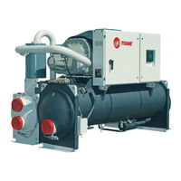
Trane RTHD series Installation, Operation And Maintanance (150 pages)
Series R Helical Rotery Liquid Chillers with heat recovery option. 175-450 ton units (60 Hz), 125-410 ton units (50 Hz)
Brand:
Trane
| Category:
Chiller
| Size: 13.4 MB
Table of Contents
Warnings, Cautions and Notices
2
Table of Contents
3
General Information
7
Unit Identification - Nameplates
7
Unit Nameplates
7
Unit Inspection
7
Inspection Checklist
7
Loose Parts Inventory
7
Unit Description
8
Model Number Coding System
8
Unit Model Number
8
Model Number (Located on Compressor Nameplate)
12
RTHD Unit
12
Installation Overview
17
RTHD Partial Heat Reclaim Unit (Back View)
17
Installation Mechanical
25
Storage
25
Location Requirements
25
Noise Considerations
25
Foundation
25
Vibration Eliminators
25
Clearances
25
Ventilation
27
Water Drainage
27
Access Restrictions
27
Moving and Rigging
27
Rigging
31
Lifting Procedure
31
Alternate Moving Method
33
Isolation Pads
33
Placement Neoprene Isolator Installation (Optional)
34
Unit Leveling
35
Water Piping
35
Piping Connections
35
Reversing Water Boxes
35
Connections - BCL
46
Figure 24. Condenser and Evaporator Water Connections - CEM
47
Figure 25. Condenser and Evaporator Water Connections - CFM/DFM
48
Figure 26. Condenser and Evaporator Water Connections - DGN/EGN
49
Table 13. Evaporator and Condenser Data
50
Contents
46
Water Pressure Drop Data
51
Making Grooved Pipe Connections
55
Vents and Drains
55
Evaporator Piping Components
55
Entering Chilled Water Piping
55
Leaving Chilled Water Piping
55
Condenser Piping Components
55
Entering Condenser Water Piping
55
Leaving Condenser Water Piping
55
Condenser Water Regulating Valve
56
Condenser Water Regulating Valve Adjust- Ment
56
Partial Heat Recovery Condenser Tube Parts
56
Full Heat Recovery Condenser Tube Parts
56
Full Heat Recovery Condenser Water Tem- Perature Requirements and Control
57
Installation of Water Tank Temperature Sensor
57
Water Treatment
57
Water Pressure Gauges and Thermometers
57
Water Pressure Relief Valves
58
Flow Sensing Devices
58
Figure 27. Typical Thermometer, Valving, and Manifold Pressure Gauge Set-Up
58
Refrigerant Pressure Relief Valve Venting
59
Table 14. Pressure Relief Valve Data
60
Thermal Insulation
61
Waterbox Removal and Installation
62
Introduction
62
Discussion
62
Procedure
62
Reassembly
63
Parts Ordering Information
63
M12X1.75)
63
Figure 30. Water Box Rigging and Lifting – Ver Tical Lift Only
63
Questions
64
Installation Electrical
65
General Recommendations
65
Power Supply Wiring
65
Water Pump Power Supply
65
Electrical Panel Power Supply
65
Ing
65
Routing
69
Module Connections for Interconnecting Wir- Ing
70
Interconnecting Wiring (Field Wiring Re- Quired)
70
Chilled Water Pump Control
70
Chilled Water Flow Interlock
70
Condenser Water Pump Control
70
Condenser Water Flow Interlock
70
Heat Recovery Pump Control
71
Heat Recovery Water Flow Interlock
71
Chilled Water Reset (CWR)
71
Equations for Calculating CWR
71
Emergency Stop
72
External Auto/Stop
72
Table 20. Chiller Events/Status Descriptions
72
Soft Loading
73
External Base Loading - Optional
73
Base Loading Control Setpoint
73
Summit Interface - Optional
73
Operating Principles Mechanical
74
General
74
Refrigeration (Cooling) Cycle
74
Cycle Description
74
Compressor Description
76
Compressor Motor
77
Compressor Rotors
77
Slide Valve Movement
77
Oil Management System
77
Oil Separator
77
Oil Flow Protection
78
Oil Filter
79
Compressor Bearing Oil Supply
79
Compressor Rotor Oil Supply
79
Lubricant Recovery
79
Oil Cooler
79
Operator Interface Controls
80
UC800 Overview
80
Power Supply
80
Wiring and Port Descriptions
80
Communication Interfaces
81
Rotary Switches
81
LED Description and Operation
81
Controls Interface
81
TD7 Display
81
Tracer TU
81
Tracer Adaptiview™Td7
81
Operator Interface
81
Main Display Area/Home Screen
82
Viewing Chiller Operating Modes
82
Alarms
85
Viewing the Alarms Screen
85
Reports
85
Viewing the Reports Screen
85
Editing a Custom Report
85
Equipment Settings
87
Viewing the Settings Screen
87
Viewing and Changing Equipment Settings
87
Screen
87
(Chiller Settings Shown)
88
Display Settings
89
Viewing the Settings Screen
89
Viewing and Changing Display Preferences
89
Contents
91
Cleaning the Display
91
Security Settings
91
Disabling/Enabling Security
91
Figure 63. Security Screen
91
Logging in
92
Logging out
92
Tracertu
93
Unit Start-Up
94
Power up
94
Power up to Starting
95
Stopped to Starting
95
Limit Conditions
96
Seasonal Unit Start-Up Procedure
96
Unit Shutdown
100
Normal Shutdown to Stopped
100
Seasonal Unit Shutdown
100
Periodic Maintenance
101
Overview
101
Weekly Maintenance and Checks
101
Monthly Maintenance and Checks
101
Annual Maintenance
101
Scheduling Other Maintenance
102
Operating Log
102
Maintenance Procedures
105
Cleaning the Condenser
105
Mechanical Cleaning Procedure
105
Chemical Cleaning Procedure
105
Cleaning the Evaporator
105
Compressor Oil
105
Oil Sump Level Check
105
Removing Compressor Oil
106
Oil Charging Procedure
106
Figure 72. Determining Oil Level in Sump
106
Replacing the Main Oil Filter (Hot Filter)
107
Replacing the Gas Pump Oil Filter
107
Refrigerant Charge
108
Evacuation and Dehydration
108
Refrigerant Charging
108
Freeze Protection
108
Diagnostics
111
Wiring Schematics
119
Unit Electrical Data
119
Advertisement
Advertisement
Related Products
Trane RTHD
Trane RTHC
Trane RTHA
Trane RTHB
Trane RTAA-140
Trane RTWA-80
Trane Sintesis RTAF 090 SE SN LN
Trane Sintesis RTAF 205 SE SN LN
Trane Sintesis RTAF 120 SE SN LN
Trane RTAF XE Series
Trane Categories
Air Conditioner
Heat Pump
Chiller
Air Handlers
Furnace
More Trane Manuals
Login
Sign In
OR
Sign in with Facebook
Sign in with Google
Upload manual
Upload from disk
Upload from URL