Sign In
Upload
Manuals
Brands
TR-Electronic Manuals
DC Drives
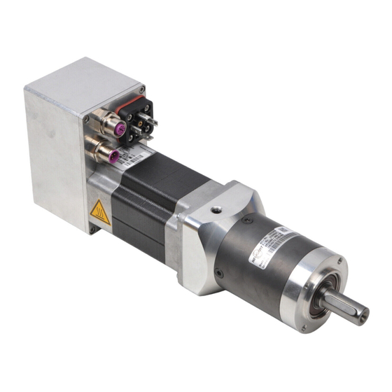
MP-200
TR-Electronic MP-200 Manuals
Manuals and User Guides for TR-Electronic MP-200. We have
2
TR-Electronic MP-200 manuals available for free PDF download: User Manual
TR-Electronic MP-200 User Manual (252 pages)
Decentralized Positioning Drives with PROFINET IO
Brand:
TR-Electronic
| Category:
DC Drives
| Size: 9 MB
Table of Contents
Deutsch
3
Inhaltsverzeichnis
3
Table of Contents
3
Änderungs-Index
10
1 Allgemeines
11
Zielgruppe
11
Geltungsbereich
11
Referenzen
12
Verwendete Abkürzungen / Begriffe
13
2 Zusätzliche Sicherheitshinweise
15
Symbol- und Hinweis-Definitionen
15
Organisatorische Maßnahmen
15
3 PROFINET Allgemeine Informationen
16
Abbildung 1: PROFINET Eingeordnet IM ISO/OSI-Schichtenmodell
16
Profinet Io
17
Real-Time Kommunikation
18
Abbildung 2: PROFINET Kommunikationsmechanismus
18
Protokollaufbau
19
Abbildung 3: Ethernet Frame Struktur
19
PROFINET IO - Dienste
20
PROFINET IO - Protokolle
20
PROFINET Systemhochlauf
21
PROFINET - Zertifikat, Weitere Informationen
21
Abbildung 4: PROFINET Systemhochlauf
21
4 Profidrive Antriebsprofil
22
Das Objektverzeichnis
22
Profidrive Objektverzeichnis
22
Zustandsmaschine, Status- und Steuerwort
23
5 PROFINET Kommunikation mit Encotrive
24
Kommunikation von Daten über PROFINET-IO
24
Abbildung 5: Encotrive am Feldbus
24
Kommunikationsbeziehung für den Zyklischen Datenaustausch
25
Zyklische Übertragung von Prozessdaten
25
Zyklische Übertragung des PKW-Kanals
25
Abbildung 6: Zyklische Kommunikation mit PKW-Kanal
25
Kommunikationsbeziehung für den Azyklischen Datenaustausch
26
Kommunikationsbeziehung für Alarme
26
Abbildung 7: Zyklische Kommunikation ohne PKW-Kanal
26
Konfiguration der Prozessdaten
27
Tabelle 1: Beispiel Freie PZD Konfiguration
27
Parameterzugriff über PKW-Kanal
30
Tabelle 2: PKW-Bereich
30
Tabelle 3: Parameterkennung (PKE)
31
Tabelle 4: PKW Fehlernummern
31
Beispiele für Parameterzugriff über PKW-Kanal
32
Leseauftrag P947[0]
32
Schreibauftrag P100 mit Wert 1000000
32
Parameterzugriff über Azyklischen Datenaustausch (Record-Data)
33
Tabelle 5: Record Data Request
33
Tabelle 6: Record Data Response
34
Beispiele für Parameterzugriff, Azyklischer Datenaustausch
35
Schreibauftrag: P930 mit Wert 2
35
Schreibauftrag: P915 mit Mehreren Werten Beschreiben
36
6 Antriebsspezifische Funktionen
40
Allgemeine Zustandsmaschine
40
Abbildung 8: Profidrive Zustandsmaschine, Allgemeiner Teil
41
Steuerwort und Zustandswort
42
Tabelle 7: Steuerwort P967 (STW)
42
Tabelle 8: Zustandswort P968 (ZSW)
43
Betriebsartanwahl
44
Betriebsart Positionieren
44
Zustandsmaschine Betriebsart "Positionieren
44
Tabelle 9: Encotrive-Betriebsarten (Werte für Parameter 930)
44
Abbildung 9: Profidrive Zustandsmaschine, Betriebsart Positionieren
45
Tabelle 10: Steuerwort P967 Positionieren
46
Tabelle 11: Zustandswort P968 Positionieren
46
Referenzieren
47
Positionierungen Durchführen
47
Abbildung 10: Rampeneinstellungen
47
Positionieren über Fahrsatztabelle
48
Stillstandüberwachung
48
Funktion
48
Tabelle 12: Parameter, die eine Positionierung Beeinflussen
48
Betriebsart Geschwindigkeitsregelung
49
Zustandsmaschine Betriebsart "Geschwindigkeitsregelung
49
Abbildung 11: Profidrive Zustandsmaschine, Betriebsart Geschwindigkeitsregelung
50
Tabelle 13: Steuerwort Geschwindigkeitsregelung
51
Tabelle 14: Zustandswort Geschwindigkeitsregelung
51
Tabelle 15: Parameter, die eine Positionierung Beeinflussen
52
Abbildung 12: Rampeneinstellungen
52
Umrechnung in Physikalische Einheiten
53
Umrechnung von Positionseinheiten
53
Abbildung 13: Spindelanwendung
53
Abbildung 14: Zahnriemenanwendung
54
Umrechnungen von Geschwindigkeits- und Beschleunigungseinheiten
55
Tabelle 16: Parameter zur Umrechnung von Einheiten
55
Standardsignale nach Profidrive
56
Tabelle 17: Standardsignale bei Encotrive
56
Verfahrbereich und Referenzpunktkoordinate
57
Tabelle 18: für die Definition des Verfahrbereichs Relevante Parameter
57
Definition des Tatsächlichen Verfahrbereichs
58
Tabelle 19: Beispiele aus der Berechnung des Maximalen Verfahrbereichs
58
Definition der Referenzpunktkoordinate
59
Tatsächlicher Verfahrbereich Z = Max. Verfahrbereich X
59
Tatsächlicher Verfahrbereich < Maximaler Verfahrbereich/2
59
Abbildung 15: Software-Endschalterpositionen / Referenzpunktkoordinate
59
Abbildung 16: Maximale Referenzpunktkoordinate, Z < X/2
59
Tatsächlicher Verfahrbereich > Maximaler Verfahrbereich/2
60
Abbildung 17: Maximale Referenzpunktkoordinate, Z > X/2
60
Rundachse mit Modulokorrektur
61
Beschreibung
61
Abbildung 18: Modulokorrektur bei Rundtischanwendng
61
Parametrierung der Rundachse
62
Tabelle 20: für die Definition des Verfahrbereichs Relevante Parameter
62
Tabelle 21: Parameterbeispiele für Rundachsfunktion
62
Referenzieren
63
Betriebsarten bei Parametrierter Rundachse
63
Positioniermode
63
Geschwindigkeitsmode
63
Beispiel Fliegender Betriebsartwechsel
64
Besondere Hinweise
64
7 Störungen und Warnungen
65
Störungen
65
Tabelle 22: Parameterstruktur P947 Störungen
65
Tabelle 23: Encotrive Störnummern
66
Warnungen
67
Tabelle 24: Warnungen bei Encotrive (Parameter 953)
67
8 Das Objektverzeichnis
68
Parameterarten
68
Datentypen
68
Abbildung 19: Encotrive Objektverzeichnis
68
Tabelle 25: Profidrive-Datentypen, die von Encotrive Verwendet werden
69
Parameterbeschreibung
70
Tabelle 26: Parameterbeschreibung
70
Speicherung des OV IM EEPROM / Werksvoreinstellungen
71
Liste der Encotrive-Parameter
72
Herstellerspezifische Parameter
73
PNU 001, Getriebefaktor
73
PNU 002, Steigung
73
PNU 003, Referenzpunkt-Koordinate
73
PNU 004, Invertierung
73
PNU 006, Verfahrbereich
74
PNU 100, Lageistwert
74
PNU 101, Stromistwert
74
PNU 102, Temperatur
74
Pnu 103, Nist_A
74
PNU 104, Spg.-Leistung
74
PNU 200, Zielposition
75
PNU 201, Geschwindigkeit
75
PNU 202, Beschleunigung
75
PNU 203, Verzögerung
75
PNU 204, JOG Geschwindigkeit
75
PNU 205, JOG Beschleunigung
75
PNU 206, JOG Verzögerung
76
PNU 300, Software-Endschalter Min
76
PNU 301, Software-Endschalter Max
76
PNU 302, Strom Max
76
PNU 304, Zielbereich
77
PNU 305, Schleppabstand
77
PNU 306, Temperatur Max
77
PNU 307, Überstrom
77
PNU 308, Temperatur Warnung
78
PNU 309, Stillstandsbereich
78
PNU 310, Überwachungszeit
78
Pnu 400, Stw2
78
Pnu 401, Zsw2
78
PNU 402, Satzanwahl
78
PNU 403, Aktueller Satz
79
PNU 500, Passwort
79
PNU 501, Kv_Proportional
79
PNU 502, Kv_Differential
79
PNU 503, Kv_Integral
80
PNU 505, Geberauflösung
80
PNU 508, Haltebremse
80
PNU 514, Max_Drehzahl
80
PNU 515, Max_Beschleunigung
81
PNU 520, Betriebsstunden
81
PNU 802, Parameter Initialisiert
81
PNU 803, Digital_Input; MD-300
81
PNU 804, Digital_Output; MD-300
81
PNU 805, Referenzpunkt Gesetzt
81
PNU 807, Dig in Funktion; MD-300
82
PNU 808, Dig out Funktion; MD-300
82
PNU 809, Entprelldauer E; MD-300
82
Profilspezifische Parameter
83
PNU 915, PZD Konfiguration Sollwerte
83
PNU 916, PZD Konfiguration Istwerte
83
PNU 922, Telegramm Auswahl
83
PNU 923, Standardsignale
83
PNU 927, Bedienhoheit
84
PNU 928, PZD Führungshoheit
84
PNU 930, Betriebsart
84
PNU 947, Fehler/Störungen
84
PNU 953, Warnung
84
PNU 964, Geräteidentifikation
85
PNU 965, Profilnummer
85
Pnu 967, Stw
85
Pnu 968, Zsw
85
PNU 970, Werksvoreinstellung Laden
85
PNU 971, IM Flash Speichern
86
PNU 980, Liste aller Parameter
86
9 Funktion Digital- Eingänge / -Ausgänge; MD-300 Baureihe
87
Grundfunktionen
87
Eingänge
87
Ausgänge
87
Funktionszuordnung
88
Eingänge
88
Realisierung der Hardware-Endschalter-Funktion
88
Tabelle 27: Struktur des Parameters 807 „Dig in Funktion
88
Abbildung 20: Funktionsprinzip Hardware-Endschalter
88
Ausgänge
89
Tabelle 28: Funktionsübersicht der Endschalter
89
10 Installationshinweise
90
11 Inbetriebnahme
91
Gerätebeschreibungsdatei (XML)
91
Geräteidentifikation
91
Abbildung 21: GSDML-Datei für die Konfiguration [Quelle: PROFIBUS International]
91
Datenaustausch bei PROFINET IO
92
Abbildung 22: Geräte-Kommunikation
92
Adressvergabe
93
MAC-Adresse
94
IP-Adresse
94
Subnetzmaske
94
Zusammenhang IP-Adresse und Default-Subnetzmaske
95
Netzübergang / Router
96
Abbildung 23: Eigenschaften - Ethernet Schnittstelle
96
12 Projektierungsbeispiel mit SIMATIC Manager
97
GSDML-Datei Installation
97
Abbildung 24: GSDML Datei Installieren
97
Vergabe des PROFINET-Gerätenamens
98
Abbildung 25: Ethernet-Teilnehmer Installieren
98
Abbildung 26: Netzteilnehmer Auswählen
98
Abbildung 27: Ethernet-Teilnehmer Bearbeiten
99
Encotrive in das Netzwerk mit Aufnehmen
100
Abbildung 28: Encotrive in das Netzwerk mit Aufnehmen
100
Abbildung 29: Vergabe des Gerätenamens in der Konfiguration
100
Telegrammauswahl
101
Erstinbetriebnahme, Manuelles Ansteuern Mithilfe der Variablentabelle
101
Abbildung 30: Ansteuern Mithilfe Variablentabelle
101
Parametrierung über PROFINET
102
13 Projektierungsbeispiel mit TIA Portal
103
GSDML-Datei Installation
103
Abbildung 31: GSDML Datei Installieren
103
Vergabe des PROFINET-Gerätenamens
104
Abbildung 32: PROFINET-Gerätename Vergeben
104
Abbildung 33: Rücksetzen auf Werkseinstellung
105
Encotrive in das Netzwerk mit Aufnehmen
106
Abbildung 34: Encotrive in das Netzwerk mit Aufnehmen
106
Abbildung 35: Vergabe des Gerätenamens in der Konfiguration
106
Telegrammauswahl
107
Erstinbetriebnahme, Manuelles Ansteuern über Beobachtungstabelle
108
Parametrierung über PROFINET
108
Abbildung 36: Ansteuern Mithilfe Beobachtungstabelle
108
14 Vorgehensweise zum Positionieren, Referenzieren und Tippen
109
Antrieb in Betriebsart „Positioning Mode" Versetzen
109
Referenzieren
110
Tippbetrieb
110
Positionieren
111
15 Webserver
112
Beschreibung
112
Security-Hinweis
112
Webbrowser
112
Verbindung zum Webserver Herstellen
112
Spracheinstellung
112
Seiten Aktualisierungszeit
113
Webseiten
113
IDENTIFIKATION (Startseite)
113
Abbildung 37: Webserver, IDENTIFICATION
113
Status
114
Abbildung 38: Webserver, STATUS
114
Diagnose
115
Abbildung 39: Webserver, DIAGNOSE
115
Diagnosepuffer
116
Abbildung 40: Webserver, DIAGNOSEPUFFER
116
Mechanik
117
Abbildung 41: Webserver, MECHANIK
117
Fahrparameter
118
Abbildung 42: Webserver, FAHRPARAMETER
118
Begrenzung
119
Abbildung 43: Webserver, BEGRENZUNG
119
Regler
120
Abbildung 44: Webserver, REGLER
120
Rt-Kommnikation
121
Abbildung 45: Webserver, RT-KOMMNIKATION
121
Info
122
Abbildung 46: Webserver, INFO
122
16 Unterschied PROFIBUS => PROFINET
123
Tabelle 29: Unterschiede PROFIBUS => PROFINET
124
17 Die Häufigsten Kundenfragen
125
English
129
Contents
129
Revision Index
136
1 General Information
137
Target Group
137
Applicability
137
References
138
Abbreviations Used / Terminology
139
2 Additional Safety Instructions
141
Definition of Symbols and Instructions
141
Organizational Measures
141
3 PROFINET General Information
142
Figure 1: PROFINET Organized in the ISO/OSI Layer Model
142
Profinet Io
143
Real-Time Communication
144
Figure 2: PROFINET Communication Mechanism
144
Protocol
145
Figure 3: Ethernet Frame Structure
145
PROFINET IO - Services
146
PROFINET IO - Protocols
146
PROFINET System Boot
147
PROFINET - Certificate, Further Information
147
Figure 4: PROFINET System Boot
147
4 Profidrive Drive Profile
148
The Object Directory
148
Profidrive Object Directory
148
State Machine, Status and Control Word
149
5 PROFINET Communication with Encotrive
150
Data Communication Via PROFINET-IO
150
Figure 5: Encotrive at the Field Bus
150
Communication Relationship for Cyclic Data Exchange
151
Cyclic Transmission of Process Data
151
Cyclic Transmission of the PKW Channel
151
Figure 6: Cyclic Communication with PKW Channel
151
Communication Relationship for Acyclic Data Exchange
152
Communication Relationship for Alarms
152
Figure 7: Cyclic Communication Without PKW Channel
152
Configuration of Process Data
153
Table 1: Example Free PZD Configuration
153
Access to Parameters Via PKW Channel
156
Table 2: PKW Range
156
Table 3: Parameter Identification (PKE)
157
Table 4: PKW Error Numbers
157
Examples of Access to Parameters Via PKW Channel
158
Read Command P947[0]
158
Write Command P100 with Value 1000000
158
Parameter Access Via Acyclic Data Exchange (Record Data)
159
Table 5: Record Data Request
159
Table 6: Record Data Response
160
Examples of Access to Parameters Via Acyclic Data Exchange
161
Write Command: Write P930 with Value 2
161
Write Command: Write P915 with a Number of Values
162
6 Drive-Specific Functions
166
General State Machine
166
Figure 8: Profidrive State Machine, General Part
167
Control Word and Status Word
168
Table 7: Control Word P967 (STW)
168
Table 8: Status Word P968 (ZSW)
169
Operating Mode Selection
170
Positioning Mode
170
State Machine of the Operating Mode "Positioning
170
Table 9: Encotrive Operating Modes (Values for Parameter 930)
170
Figure 9: Profidrive State Machine, Positioning Mode
171
Table 10: Control Word P967 Positioning
172
Table 11: Status Word P968 Positioning
172
Referencing
173
Positionings
173
Figure 10: Ramp Settings
173
Positionings Via Travel Command Table
174
Standstill Monitoring
174
Function
174
Table 12: Parameters Affecting a Positioning Movement
174
Speed Control Mode
175
State Machine of the Operating Mode "Speed Control
175
Figure 11: Profidrive State Machine, Speed Control Mode
176
Table 13: Control Word, Speed Control
177
Table 14: Status Word, Speed Control
177
Table 15: Parameters Affecting a Positioning Movement
178
Figure 12: Ramp Settings
178
Conversion into Physical Units
179
Conversion of Position Units
179
Figure 13: Spindle Application
179
Figure 14: Belt Application
180
Conversion of Speed- and Acceleration Units
181
Table 16: Parameters for Converting Units
181
Standard Signals According to Profidrive
182
Table 17: Standard Signals for Encotrive
182
Travel Range and Reference Point Coordinates
183
Table 18: Relevant Parameters for Definition of the Travel Range
183
Definition of the Real Travel Range
184
Table 19: Examples from Calculation of the Maximum Travel Range
184
Definition of the Reference Point Coordinate
185
Real Travel Range Z = Max. Travel Range X
185
Real Travel Range < Max. Travel Range/2
185
Figure 15: Software Limit Switch Positions / Reference Point Coordinate
185
Figure 16: Max. Reference Point Coordinate, Z < X/2
185
Real Travel Range > Max. Travel Range/2
186
Figure 17: Max. Reference Point Coordinate, Z > X/2
186
Rotary Axis with Modulo Correction
187
Description
187
Figure 18: Modulo Correction at Rotary Table Application
187
Definition of the Reference Point Coordinate
188
Table 20: Parameters Relevant to the Definition of the Travel Range
188
Table 21: Parameter Examples for Rotary Axis Function
188
Referencing
189
Operating Modes with Parameterized Rotary Axis
189
Positioning Mode
189
Speed Mode
189
Example of Flying Mode Change
190
Special Instructions
190
7 Faults and Warnings
191
Faults
191
Table 22: Parameter Structure for P947 Faults
191
Table 23: Encotrive Fault Numbers
192
Warnings
193
Table 24: Encotrive Warnings (Parameter 953)
193
8 The Object Directory
194
Types of Parameter
194
Data Types
194
Figure 19: Encotrive Object Directory
194
Table 25: Profidrive Data Types Used by Encotrive
195
Description of Parameters
196
Table 26: Description of Parameters
196
Saving the Object Directory in Flash / Factory Settings
197
List of Encotrive Parameters
198
Manufacturer-Specific Parameters
199
PNU 001, Gearbox Factor
199
PNU 002, Pitch
199
PNU 003, Reference Point Coordinate
199
PNU 004, Inversion
199
PNU 006, Travel Range
200
PNU 100, Actual Value of Position
200
PNU 101, Actual Value of Current
200
PNU 102, Temperature
200
Pnu 103, Nist_A
200
PNU 104, Power Voltage
200
PNU 200, Target Position
201
PNU 201, Speed
201
PNU 202, Acceleration
201
PNU 203, Deceleration
201
PNU 204, JOG Speed
201
PNU 205, JOG Acceleration
201
PNU 206, JOG Deceleration
202
PNU 300, Software Limit Switch Min
202
PNU 301, Software Limit Switch Max
202
PNU 302, Max. Current
202
PNU 304, Target Range
203
PNU 305, Tracking Distance
203
PNU 306, Max. Temperature
203
PNU 307, Overcurrent
203
PNU 308, Temperature Warning
204
PNU 309, Standstill Range
204
PNU 310, Monitoring Time
204
Pnu 400, Stw2
204
Pnu 401, Zsw2
204
PNU 402, Command Set Selection
204
PNU 403, Current Command Set
205
PNU 500, Password
205
PNU 501, Kv_Proportional
205
PNU 502, Kv_Differential
205
PNU 503, Kv_Integral
206
PNU 505, Encoder Resolution
206
PNU 508, Stop Brake
206
PNU 514, Max_Speed
206
PNU 515, Max_Acceleration
207
PNU 520, Operating Hours
207
PNU 802, Parameter Initialized
207
PNU 803, Digital_Input; MD-300
207
PNU 804, Digital_Output; MD-300
207
PNU 805, Reference Point Set
207
PNU 807, Digital in Function; MD-300
208
PNU 808, Digital out Function; MD-300
208
PNU 809, Debounce Time E; MD-300
208
Profile-Specific Parameters
209
PNU 915, PZD Configuration Setpoints
209
PNU 916, PZD Configuration Actual Values
209
PNU 922, Telegram Selection
209
PNU 923, Standard Signals
209
PNU 927, Control Priority
210
PNU 928, PZD Control Priority
210
PNU 930, Operating Mode
210
PNU 947, Error/Faults
210
PNU 953, Warning
210
PNU 964, Device Identification
211
PNU 965, Profile Number
211
Pnu 967, Stw
211
Pnu 968, Zsw
211
PNU 970, Load Factory Setting
211
PNU 971, Save in Flash
212
PNU 980, List of All Parameters
212
9 Function of the Digital Inputs / Outputs; MD-300
213
Basic Functions
213
Inputs
213
Outputs
213
Function Assignment
214
Inputs
214
Implementation of the Hardware Limit Switch Function
214
Table 27: Structure of the Parameter 807 "Digital in Function
214
Figure 20: Functional Principle of the Hardware Limit Switches
214
Outputs
215
Table 28: Overview of the Limit Switch Function
215
10 Installation Notes
216
11 Commissioning
217
Device Description File (XML)
217
Device Identification
217
Figure 21: GSDML File for the Configuration [Source: PROFIBUS International]
217
PROFINET IO Data Exchange
218
Figure 22: Device Communication
218
Distribution of IP Addresses
219
MAC-Address
220
IP-Address
220
Subnet Mask
220
Combination IP-Address and Default Subnet Mask
221
Gateway / Router
222
Figure 23: Properties - Ethernet Interface
222
12 Configuration Example with SIMATIC Manager
223
Installation of the GSDML File
223
Figure 24: Installing the GSDML File
223
Allocation of the PROFINET Device Name
224
Figure 25: Installation of Ethernet Nodes
224
Figure 26: Selection of Network Nodes
224
Figure 27: Edit Ethernet Node
225
Incorporating Encotrive into the Network
226
Figure 28: Incorporating Encotrive into the Network
226
Figure 29: Allocation of the Device Name in the Configuration
226
Telegram Selection
227
Initial Commissioning, Manual Control with the Variables Table
227
Figure 30: Control with the Help of the Variables Table
227
Parameterization Via PROFINET
228
13 Configuration Example with TIA Portal
229
Installation of the GSDML File
229
Figure 31: Installation of the GSDML File
229
Allocation of the PROFINET Device Name
230
Figure 32: Allocation of the PROFINET Device Name
230
Figure 33: Reset to Default Settings
231
Incorporating Encotrive into the Network
232
Figure 34: Incorporating Encotrive into the Network
232
Figure 35: Allocation of the Device Name in the Configuration
232
Telegram Selection
233
Initial Commissioning, Manual Control with the Monitoring Table
234
Parameterization Via PROFINET
234
Figure 36: Manual Control with the Monitoring Table
234
14 Procedure for Positioning, Referencing and Jogging
235
Set Drive to "Positioning Mode
235
Referencing
236
Jog Mode
236
Positioning
237
15 Webserver
238
Description
238
Security Notes
238
Web Browser
238
Establishing a Connection to the Web Server
238
Language Setting
238
Page Refresh Time
239
Web
239
IDENTIFICATION (Start Page)
239
Figure 37: Web Server, IDENTIFICATION
239
State
240
Figure 38: Web Server, STATE
240
Diagnostics
241
Figure 39: Web Server, DIAGNOSTICS
241
Diagnostic Buffer
242
Figure 40: Web Server, DIAGNOSTIC BUFFER
242
Mechanics
243
Figure 41: Web Server, MECHANICS
243
Drive Parameters
244
Figure 42: Web Server, DRIVE PARAMETERS
244
Limits
245
Figure 43: Web Server, LIMITS
245
Regulator
246
Figure 44: Web Server, REGULATOR
246
Rt-Communication
247
Figure 45: Web Server, RT-COMMUNICATION
247
Info
248
Figure 46: Web Server, INFO
248
16 Differences between PROFIBUS => PROFINET
249
Table 29: Differences between PROFIBUS => PROFINET
250
17 Faq´s
251
Advertisement
TR-Electronic MP-200 User Manual (153 pages)
Decentralized positioning drives
Brand:
TR-Electronic
| Category:
DC Drives
| Size: 3 MB
Table of Contents
Table of Contents
3
Contents
3
List of Tables
8
List of Figures
9
List of Formulas
9
Revision Index
10
General Information
11
Target Group
11
Applicability
11
References
12
Table 1: References
12
Abbreviations Used / Terminology
13
Table 2: Abbreviations Used / Terminology
14
Additional Safety Instructions
15
Definition of Symbols and Instructions
15
Organizational Measures
15
Technical Data
16
Current Firmware Versions
16
Electrical Characteristics
16
Ethercat / DS-402
17
CE Conformity
18
Ethercat Information
19
Ethercat Functional Principle
19
Figure 1: Ethercat Functional Principle
19
Protocol
20
Figure 2: Ethernet Frame Structure
20
Ethercat State Machine (ESM)
21
Table 3: States, State Machine
21
Figure 3: Ethercat State Machine
21
Transition into the OPERATIONAL State
22
Device Profile
23
Figure 4: Canopen over Ethercat Communication Mechanism
23
Canopen over Ethercat (Coe)
24
Figure 5: Canopen Organized in the ISO/OSI Layer Model
24
Figure 6: Ethercat Organized in the ISO/OSI Layer Model
24
Object Dictionary
25
Process and Service Data Objects
25
Figure 7: Structure of the Object Dictionary
25
Figure 8: Comparison of PDO/SDO Characteristics
25
Compatibility with the Cia DS-301 Communication Profile
26
Transmission of SDO Messages
27
PDO Mapping
29
Further Information
29
DSP 402 Drive Profile
30
DSP 402 State Machine
31
Figure 9: DSP 402 State Machine
31
Operating Condition
32
Table 4: States of the Status Word
32
Table 5: Operating States, Status Word
32
State Transitions
33
Change Mode of Operation
34
Table 6: State Transitions
34
Table 7: Change Operating State
34
Profile Position (PP)" Operating Mode
35
Control Word
35
Table 8: Control Word (Object 0X6040), "Profile Position" Operating Mode
35
Status Word
36
Table 9: Status Word (Object 0X6041), "Profile Position" Operating Mode
36
Perform Positioning
37
Figure 10: Positioning Ramp
37
Absolute / Relative Positioning
38
Figure 11: Absolute Positioning (Top) and Relative Positioning (Bottom)
38
Transfer of New Movement Records
39
Termination of a Positioning Movement
39
Relevant Parameters
39
Table 10: Positioning Parameter
39
Profile Velocity (PV)" Operating Mode
40
Control Word
40
Table 11: Control Word (Object 0X6040), "Profile Velocity" Operating Mode
40
Status Word
41
Table 12: Status Word (Object 0X6041), "Profile Velocity" Operating Mode
41
Perform Speed Ramp
42
Figure 12: Speed Ramp
42
Relevant Parameters
43
Table 13: Speed Ramp Parameter
43
Homing (HM)" Operating Mode
44
Control Word
44
Table 14: Control Word (Object 0X6040), "Homing" Operating Mode
44
Status Word
45
Table 15: Status Word (Object 0X6041), "Homing" Operating Mode
45
Table 16: Definition of the Homing Status Bits 10, 12, 13
45
Perform Position Adjustment
46
Relevant Parameters
46
Cyclic Synchronous Position (CSP)" Operating Mode
47
Control Word
47
Table 17: Control Word (Object 0X6040), "Cyclic Synchronous Position (CSP)" Operating Mode
47
Status Word
48
Table 18: Status Word (Object 0X6041), "Cyclic Synchronous Position (CSP)" Operating Mode
48
Perform Operating Mode
49
Relevant Parameters
49
Figure 13: Cyclic Synchronous Position Control Function (CSP)
49
Cyclic Synchronous Velocity (CSV)" Operating Mode
50
Control Word
50
Table 19: Control Word (Object 0X6040), "Cyclic Synchronous Velocity (CSV)" Operating Mode
50
Status Word
51
Table 20: Status Word (Object 0X6041), "Cyclic Synchronous Velocity (CSV)" Operating Mode
51
Perform Operating Mode
52
Relevant Parameters
52
Figure 14: Cyclic Synchronous Velocity Control Function (CSV)
52
Cyclic Synchronous Torque (CST)" Operating Mode
53
Control Word
53
Table 21: Control Word (Object 0X6040), "Cyclic Synchronous Torque (CST)" Operating Mode
53
Status Word
54
Table 22: Status Word (Object 0X6041), "Cyclic Synchronous Torque (CST)" Operating Mode
54
Perform Operating Mode
55
Relevant Parameters
55
Figure 15: Cyclic Synchronous Torque Control Function (CST)
55
Units
56
Object 0X608F: Position Encoder Resolution
56
Object 0X6090: Speed Encoder Resolution
56
Formula 1: Position Encoder Resolution
56
Formula 2: Default Value, Position Encoder Resolution
56
Formula 3: Speed Encoder Resolution
56
Formula 4: Default Value, Speed Encoder Resolution
56
Object 0X6093: Position Factor
57
Formula 5: Position Factor
57
Formula 6: Gear Ratio
57
Formula 7: Default Value, Position Factor
57
Object 0X6094: Speed Factor
59
Formula 8: Speed Factor
59
Formula 9: Default Value, Speed Factor
59
Object 0X6097: Acceleration Factor
61
Formula 10: Acceleration Factor
61
Formula 11: Default for Acceleration Factor
61
Installation- / Connection Notes, Pin Assignments
66
Optional Holding Brake / Ballast Circuit
67
Commissioning
67
Device Description File
67
Object Directory
68
Object Types, Data Types
68
Table 23: Object Codes in Encotrive
68
Table 24: Attributes
68
Table 25: Encotrive Data Types
68
Communication-Specific Standard Objects Cia DS-301
69
Table 26: Communication Specific Standard Objects
69
Object 0X1000: Device Type
70
Object 0X1001: Error Register
70
Object 0X1003: Pre-Defined Error Field
71
Object 0X1008: Manufacturer's Device Name
72
Object 0X1009: Manufacturer's Hardware Version
72
Object 0X100A: Manufacturer's Software Version
72
Object 0X1010: Save Backup Parameters
73
Object 0X1011: Reset Backup Parameters
74
Object 0X1018: Identity
75
Structure of the Mapping Parameter
76
Objects 0X1600-0X1601: Receive PDO Mapping
77
Objects 0X1A00-0X1A01: Transmit PDO Mapping
78
Object 0X1C00: Sync Manager Communication Type
79
Object 0X1C12: SM2 PDO Assignment
81
Object 0X1C13: SM3 PDO Assignment
82
Manufacturer-Specific Objects
83
Object 0X2Ef3: Trabedata.mvi16
83
Object 0X2F04: DS402M.MPU32
85
Object 0X2F0E: DS402M.MPX
89
Objects of the DSP 402 Device Profile
91
Table 27: Profile Specific Objects
92
Object 0X6007: Abort Connection Code
93
Object 0X603F: Error Code
93
Object 0X6040: Control Word
93
Object 0X6041: Status Word
94
Object 0X605A: Quick Stop Option Code
94
Table 28: Values for Quick Stop Option Code
94
Object 0X605B: Shutdown Option Code
95
Object 0X605C: Disable Operation Option Code
95
Table 29: Values for Shutdown Option Code
95
Table 30: Values for Disable Operation Option Code
95
Object 0X605D: Stop Option Code
96
Object 0X605E: Fault Reaction Option Code
96
Table 31: Values for Halt Option Code
96
Table 32: Values for Fault Reaction Option Code
96
Object 0X6060: Operation Mode
97
Object 0X6061: Operation Mode Display
97
Object 0X6062: Required Position
97
Table 33: Values for Operating Mode
97
Object 0X6064: Actual Position
98
Object 0X6065: Following Error Window
98
Object 0X6066: Following Error Timeout
98
Object 0X6067: In-Position Window
99
Object 0X6068: In-Position Timeout
99
Object 0X6069: Sensor Velocity
99
Object 0X606B: Required Velocity
100
Object 0X606C: Actual Velocity
100
Object 0X606D: Velocity Window
100
Object 0X606E: Velocity Window Timeout
101
Object 0X606F: Velocity Threshold
101
Object 0X6070: Velocity Threshold Timeout
101
Object 0X6071: Target Torque
102
Object 0X6072: Torque Limit
102
Object 0X6073: Limit for Torque Generating Current
102
Object 0X6074: Required Torque
103
Object 0X6075: Motor Rated Current/Ma
103
Object 0X6076: Motor Rated Torque/Mnm
103
Object 0X6077: Actual Torque
104
Object 0X6078: Actual Current
104
Object 0X6079: Actual DC Link Circuit Voltage/MV
104
Object 0X607A: Target Position
105
Object 0X607B: Position Range Limits
105
Object 0X607C: Home Offset
106
Object 0X607D: Software Position Limits
106
Object 0X607E: Polarity
107
Object 0X607F: Max Profile Velocity
107
Object 0X6080: Max Motor Speed
107
Table 34: Direction Reversal
107
Object 0X6081: Profile Velocity
108
Object 0X6083: Profile Acceleration
108
Object 0X6084: Profile Deceleration
108
Object 0X6085: Quick Stop Deceleration
109
Object 0X608F: Position Encoder Resolution
109
Object 0X6090: Velocity Encoder Resolution
110
Object 0X6093: Position Factor
111
Object 0X6094: Velocity Encoder Factor
112
Object 0X6097: Acceleration Factor
113
Object 0X6098: Homing Method
113
Object 0X6099: Homing Speeds
114
Object 0X609A: Homing Acceleration
114
Object 0X60B0: Position Offset
115
Object 0X60B1: Velocity Offset
115
Object 0X60B2: Torque Offset
115
Object 0X60C5: Max Acceleration
116
Object 0X60C6: Max Deceleration
116
Object 0X60F4: Following Error
116
Object 0X60Fd: Digital Inputs
117
Object 0X60Fe: Digital Outputs
117
Object 0X60Ff: Target Velocity
118
Object 0X6402: Motor Type
118
Object 0X6502: Supported Drive Modes
118
Object 0X6508: Runtime in 0.1 Hours
119
Object 0X6510: Measuring Range in Revolutions
119
Projecting with Twincat System Manager V2.10
120
Installation of the ESI File
120
Connection of the Encotrive Device
120
Creation of a Twincat Project for an Encotrive Device
121
Changing Data Objects
122
Storing and Resetting Backup Parameters
123
Stop Conditions, Digital Inputs and Hardware Limit Switches
124
Turning on the Drive
124
Stop Conditions: Priorities, Behavior
124
Control of the Digital Inputs
127
Operation of the Digital Inputs as Limit Switches
128
Control Word and Status Word
131
General
131
Status Bit 2 - Warning
131
Status Bit 2 - Remote
131
Status Bit 2 10 - Target Reached
131
Status Bit 2 11 - Internal Limit Active
132
Profile Position Mode (Operating Mode 1)
133
Profile Velocity Mode (Operating Mode 3)
136
Cyclic Synchronous Modes (Operating Modes 8, 9, 10)
137
Backup-EEPROM, Runtime
137
Position Adjustment by Homing (Operating Mode 6)
138
Manual Tuning of the Position and Speed Regulation
141
Gear Backlash Cancellation (Opmodes -48=0Xd0)
143
Twincat System Manager - Example Program (Download)
144
Troubleshooting and Diagnosis Options
145
SDO Error Codes
145
Table 35: SDO Abort Codes
145
EMCY Error Information
146
Encotrive RE - Emergencies
146
Error Register, Object 0X1001
146
Table 36: EMCY Error Register, Object 0X1001
146
Error Code, Object 0X1003 (Bit 0-15)
147
General
147
Table 37: EMCY Error Code, Object 0X1003
150
Encotrive RE - Accessories, Test Setup
151
Power Supply Cables with Solenoid Valve or M23 Connectors
151
Test Parameters for "Encotrive RELC
151
Ethercat Conformance Test Tool 1.20.80.0
152
Advertisement
Related Products
TR-Electronic MP Series
TR-Electronic MP-60
TR-Electronic MP-100
TR-Electronic MP-140
TR-Electronic MP-180
TR-Electronic MP-280
TR-Electronic MA Series
TR-Electronic MA-100
TR-Electronic MA-130
TR-Electronic encoTRive MD-025-CO-C Series
TR-Electronic Categories
Media Converter
Transducer
Measuring Instruments
Enclosure
DC Drives
More TR-Electronic Manuals
Login
Sign In
OR
Sign in with Facebook
Sign in with Google
Upload manual
Upload from disk
Upload from URL