Sign In
Upload
Manuals
Brands
TR-Electronic Manuals
Media Converter
LMRB-27
TR-Electronic LMRB-27 Linear Encoder Manuals
Manuals and User Guides for TR-Electronic LMRB-27 Linear Encoder. We have
6
TR-Electronic LMRB-27 Linear Encoder manuals available for free PDF download: User Manual, Manual, Assembly Instructions Manual
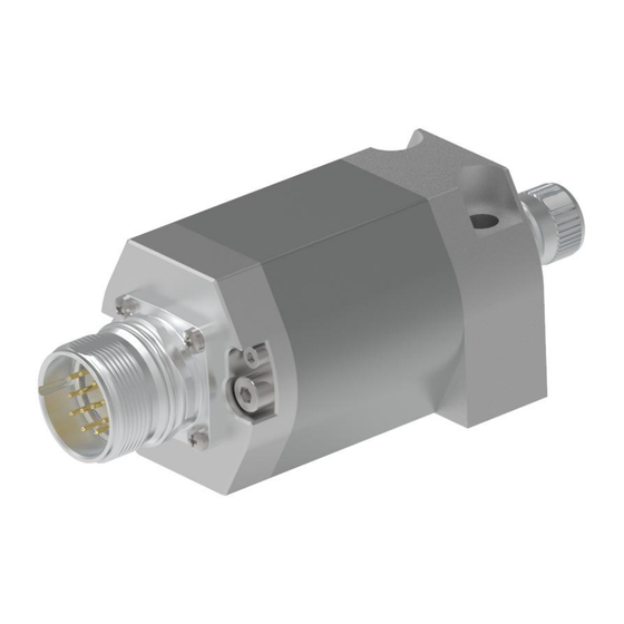
TR-Electronic LMRB-27 User Manual (138 pages)
Linear Encoder magnetostrictive
Brand:
TR-Electronic
| Category:
Media Converter
| Size: 9 MB
Table of Contents
Deutsch
4
Table of Contents
4
Änderungs-Index
5
Allgemeines
6
Geltungsbereich
6
Mitgeltende Dokumente
6
EU-Konformitätserklärung
6
Verwendete Abkürzungen und Begriffe
7
Allgemeine Funktionsbeschreibung
8
Grundlegende Sicherheitshinweise
9
Symbol- und Hinweis-Definition
9
Verpflichtung des Betreibers vor der Inbetriebnahme
9
Bestimmungswidrige Verwendung
10
Allgemeine Gefahren bei der Verwendung des Produkts
10
Bestimmungsgemäße Verwendung
10
Gewährleistung und Haftung
11
Organisatorische Maßnahmen
11
Personalauswahl und -Qualifikation; Grundsätzliche Pflichten
12
Sicherheitstechnische Hinweise
13
Transport / Lagerung
14
Montagehinweise / Schema
15
Mechanik Rohr-Gehäuseausführung
15
Mechanik Profil-Gehäuseausführung
15
Montageschema der Rohr-Gehäuseausführung
17
Einbau in Hydraulikzylinder
18
Abdichtungsvarianten
19
Axialabdichtung
19
Radialabdichtung
20
Einbauvarianten bei Magnetisierbarem Material
21
Einbaubeispiel LMR-48, Variante mit M12-Flanschstecker
22
Stecker-Montage
22
Besonderheiten
23
Erforderliches Anzugsdrehmoment
24
Berechnungsbeispiel Axialabdichtung
24
Berechnungsbeispiel Radialabdichtung
25
Zubehör
26
English
30
Revision Index
31
Applicability
32
EU Declaration of Conformity
32
General Information
32
Other Applicable Documents
32
Abbreviations and Definitions
33
General Functional Description
34
Basic Safety Instructions
35
Definition of Symbols and Instructions
35
Obligation of the Operator before Start-Up
35
General Risks When Using the Product
36
Intended Use
36
Non-Intended Use
36
Organizational Measures
37
Warranty and Liability
37
Personnel Qualification; Obligations
38
Safety Informations
39
Transportation / Storage
40
Instructions for Mounting / Schematic
41
Mechanics Profile- Housing Design
41
Mechanics Rod Housing Design
41
Assembly Diagram of the Rod Housing Design
43
Installation in Hydraulic Cylinders
44
Axial Sealing
45
Sealing Options
45
Radial Sealing
46
Installation Types with Magnetizable Material
47
Mounting Example LA-66
47
Mounting Example LMR-48, Version with M12-Male Connector
48
Plug Mounting
48
Unusual Features
49
Calculation Example Axial Sealing
50
Required Torque
50
Calculation Example Radial Sealing
51
Accessories
52
Allgemeines
58
Geltungsbereich
58
Verwendete Abkürzungen / Begriffe
59
Einsatz in Explosionsfähigen Atmosphären
60
Symbol- und Hinweis-Definition
60
Zusätzliche Sicherheitshinweise
60
SSI Informationen
61
Grundsätzliche Regeln
62
Installation / Inbetriebnahmevorbereitung
62
RS422 Übertragungstechnik
63
Anschluss - Hinweise
64
Kabelspezifikation
64
Anbindung an den PC (Programmierung)
65
SSI Schnittstelle
66
Status-Leds bei Mehrfach Redundanten Mess-Systemen
67
Grundparameter
68
Messlänge in Schritten
68
Trwinprog Parametrierung
68
Zählrichtung
68
Presetwert
69
Messlänge in MM
70
Presetfreigabe
70
Anzahl Datenbits
71
Ssi
71
Ausgabecode
72
Messanfang
72
Verschiebung
72
Anfang- / Ende Sicherheitsbereich
73
Negative Werte
73
Ausgabe SSI + Prüfsumme (Optional)
74
SSI-Wert IM Sumpf
74
Parity
75
SSI Sonderbits
75
Sumpf
75
Synchronisation
75
Up / down
75
Istwerte
76
Position/Intern
76
Sicherheitsbereich
76
Sonderbits
76
SSI-Position
76
Anzeigeform
77
Positions-Anzeige
77
Ta-Mini
77
Vorzeichen-Anzeige
77
TA-Messanfang
78
TA-Messlänge
78
Fehlerursachen und Abhilfen
79
Contents
84
Revision Index
85
Applicability
86
General Information
86
Abbreviations Used / Terminology
87
Additional Safety Instructions
88
Definition of Symbols and Instructions
88
Usage in Explosive Atmospheres
88
SSI Information
89
Basic Rules
90
Installation / Preparation for Commissioning
90
RS422 Data Transmission Technology
91
Cable Definition
92
Connection to the PC (Programming)
93
SSI Interface
94
Status Leds at Multiple Redundant Measuring Systems
95
Basic Parameters
96
Count Direction
96
Measuring Length in Steps
96
Trwinprog Parameterization
96
Preset Value
97
Measuring Length in MM
98
Preset Function
98
Number of Data Bits
99
Ssi
99
Offset
100
Offset Value
100
Transmit Code
100
Begin- / End of Safety Range
101
Negative Values
101
Magnet in Damping Zone
102
Output SSI + Checksum (Optional)
102
Damping Zone
103
Parity
103
SSI Special Bits
103
Synchronization
103
Up / down
103
Position Value
104
Position/Internal
104
Safety Range
104
Special Bits
104
SSI Position
104
Display Mode
105
Display of Position
105
Sign
105
Ta-Mini
105
TA Measuring Length
106
TA Origin
106
Causes of Faults and Remedies
107
Änderungs-Index
112
Allgemeines Gefahrenpotential
113
Sicherheit
113
Sicherheitstechnische Hinweise
113
Hinweise zur Installation
114
Abschirmung
115
Allgemeine Entstörmaßnahmen
115
Bestimmungsgemäße Verwendung
116
Sicherheitsmaßnahmen am Montageort
117
Zugelassene Bediener
117
Rotatorische Encoder
118
Synchron - Serielles - Interface
118
Ausgabe-Format "Mehrfach" (26 Bit Wiederholung)
119
Ausgabe-Format "Tannenbaum
120
Ausgabe-Format "Linksbündig
121
Ausgabe-Format "Standard
123
Lineare Encoder (LA, LP, Laser)
123
Ausgabe-Format "Mehrfach" (26 Bit Wiederholung), Optional
124
Ausgabe-Format "Linksbündig
125
Advertisement
TR-Electronic LMRB-27 Manual (135 pages)
RtherCAT +Multi sensor 3
Brand:
TR-Electronic
| Category:
Media Converter
| Size: 7 MB
Table of Contents
Deutsch
3
Table of Contents
3
Inhaltsverzeichnis
3
Änderungs-Index
5
Allgemeines
6
Geltungsbereich
6
Referenzen
7
Verwendete Abkürzungen / Begriffe
8
Ergänzende Hinweise zur Bestimmungsgemäßen Verwendung
9
Symbol- und Hinweis-Definition
9
Zusätzliche Sicherheitshinweise
9
Organisatorische Maßnahmen
10
Ethercat Informationen
11
Ethercat-Funktionsprinzip
11
Protokoll
12
Verteilte Uhren
12
Geräteprofil
13
Canopen over Ethercat (Coe)
14
Prozess- und Service-Daten-Objekte
15
Objektverzeichnis
15
Kompatibilität zum Cia DS-301 Kommunikationsprofil
16
Erweiterungen zum Cia DS-301 Kommunikationsprofil
16
Übertragung von SDO Nachrichten
17
Canopen over Ethercat Protokoll
19
Initiate SDO Download Expedited Request
19
Initiate SDO Download Expedited Response
20
Initiate SDO Upload Expedited Request
21
Initiate SDO Upload Expedited Response
22
PDO-Mapping
23
Ethercat State Machine (ESM)
23
Weitere Informationen
24
Installation / Inbetriebnahmevorbereitung
25
Anschluss
26
Einschalten der Versorgungsspannung
27
Inbetriebnahme
28
Gerätebeschreibungsdatei
28
Bus-Statusanzeige
28
Anzeigezustände und Blinkfrequenz
28
Net Run LED
29
Link / Data Activity LED, IN/OUT
29
Betriebsarten
30
Kommunikationsspezifische Standard-Objekte (Cia DS-301)
31
Objekt 1000H: Gerätetyp
32
Objekt 1008H: Hersteller Gerätenamen
32
Objekt 1009H: Hersteller Hardwareversion
33
Objekt 100Ah: Hersteller Softwareversion
33
Objekt 1018H: Identity Objekt
34
Objekt 1A00H: 1 St Transmit PDO Mapping
36
Nd Transmit PDO Mapping
38
Objekt 1A02H: 3 Rd Transmit PDO Mapping
38
Th Transmit PDO Mapping
39
Objekt 1A04H: 5 Th Transmit PDO Mapping
39
Objekt 1A05H: 6 Th Transmit PDO Mapping
39
Objekt 1C00H: Sync Manager Communication Type
41
Objekt 1C13H: Sync Manager Channel 3 (Prozess-Daten-Eingang)
43
Objekt 1C33H: Sync Manager 3, Parameter
44
Hersteller- und Profilspezifische Objekte (Cia DS-406)
47
Objekt 2001H: Interpolation
48
Objekt 2000H: Parameter Übernehmen
48
Objekt 2002H: Beobachter
49
Objekt 2003H: Positionsfilter
49
Objekt 3000H: Status
50
Objekt 3001H: Buszykluszeit
50
Objekt 3002H: Interne Zykluszeit
50
Objekt 6000H: Betriebsparameter
51
Objekt 6002H: Messlänge in Schritten
51
Objekt 6005H: Linear-Encoder, Mess-Schritt
52
Objekt 6010H: Presetwerte
54
Objekt 6020H: Positionswerte
56
Objekt 6030H: Geschwindigkeitswerte
58
Objekt 6040H: Beschleunigungswerte
60
Fehlerursachen und Abhilfen
62
Optische Anzeigen
62
Abort SDO Transfer Request Protocol
63
SDO Abort Codes
64
Emergency Request Protocol
65
Emergency Error Codes
66
Error Register
66
Sonstige Störungen
67
English
71
Contents
71
Revision Index
73
Applicability
74
General Information
74
References
75
Abbreviations Used / Terminology
76
Additional Instructions for Proper Use
77
Additional Safety Instructions
77
Definition of Symbols and Notes
77
Organizational Measures
78
Ethercat Functional Principle
79
Ethercat Information
79
Distributed Clocks
80
Protocol
80
Device Profile
81
Canopen over Ethercat (Coe)
82
Object Dictionary
83
Process and Service Data Objects
83
Compatibility with the Cia DS-301 Communication Profile
84
Extensions to the Cia DS-301 Communication Profile
84
Transmission of SDO Messages
85
Canopen over Ethercat Protocol
87
Initiate SDO Download Expedited Request
87
Initiate SDO Download Expedited Response
88
Initiate SDO Upload Expedited Request
89
Initiate SDO Upload Expedited Response
90
Ethercat State Machine (ESM)
91
PDO Mapping
91
Further Information
92
Installation / Preparation for Commissioning
93
Connection
94
Switching on the Supply Voltage
95
Bus Status Display
96
Commissioning
96
Device Description File
96
Indicator States and Flash Rates
96
Link / Data Activity LED, IN/OUT
97
Net Run LED
97
Operating Modes
98
Communication-Specific Standard Objects (Cia DS-301)
99
Object 1000H: Device Type
100
Object 1008H: Manufacturer Device Name
100
Object 1009H: Manufacturer Hardware Version
101
Object 100Ah: Manufacturer Software Version
101
Object 1018H: Identity Object
102
Object 1A00H: 1 St Transmit PDO Mapping
104
Object 1A01H: 2 Nd Transmit PDO Mapping
106
Object 1A02H: 3 Rd Transmit PDO Mapping
106
Object 1A03H: 4 Th Transmit PDO Mapping
107
Object 1A04H: 5 Th Transmit PDO Mapping
107
Object 1A05H: 6 Th Transmit PDO Mapping
108
Object 1C00H: Sync Manager Communication Type
109
Object 1C13H: Sync Manager Channel 3 (Process Data Input)
111
Object 1C33H: Sync Manager 3, Parameter
112
Manufacturer and Profile Specific Objects (Cia DS-406)
115
Object 2000H: Accept Parameters
116
Object 2001H: Interpolation
116
Object 2002H: Observer
117
Object 2003H: Position Filter
117
Object 3000H: Status
118
Object 3001H: Bus Cycle Time
118
Object 3002H: Internal Cycle Time
118
Object 6000H: Operating Parameters
119
Object 6002H: Total Measuring Range in Steps
119
Object 6005H: Linear Encoder, Measuring Step
120
Object 6010H: Preset Values
122
Object 6020H: Position Values
124
Object 6030H: Speed Values
126
Object 6040H: Acceleration Values
128
Error Causes and Remedies
130
Optical Displays
130
Abort SDO Transfer Request Protocol
131
SDO Abort Codes
132
Emergency Request Protocol
133
Emergency Error Codes
134
Error Register
134
Miscellaneous Faults
135
TR-Electronic LMRB-27 User Manual (170 pages)
Linear Encoder magnetostrictive
Brand:
TR-Electronic
| Category:
Media Converter
| Size: 10 MB
Table of Contents
Deutsch
56
Table of Contents
56
Skalierungsfunktion
87
Beschreibung der Betriebsparameter
87
Klasse 2 Funktionalität
87
Zählrichtung
87
Messlänge in Schritten
88
Fehler-Handling
88
Status
89
Geschwindigkeit - Beobachter
89
Geschwindigkeit - Format
89
Geschwindigkeit - Auflösung [0.1Mm/S]
90
Konfigurationsbeispiel, SIMATIC Manager V5.1
91
Störungsbeseitigung und Diagnosemöglichkeiten
95
Optische Anzeigen, Leds
95
Verwendung der PROFIBUS Diagnose
96
Normdiagnose
96
Stationsstatus 3
97
Stationsstatus 1
97
Stationsstatus 2
97
Masteradresse
98
Herstellerkennung
98
Länge (in Byte) der Erweiterten Diagnose
98
Erweiterte Diagnose
99
Alarme
99
Betriebsstatus
100
Encodertyp
100
Mess-Schritt
100
Anzahl Auflösbarer Umdrehungen
100
Zusätzliche Alarme
100
Profil Version
101
Unterstützte Warnungen
101
Warnungen
101
Unterstützte Alarme
101
Software Version
102
Betriebsstundenzähler
102
Offsetwert
102
Herstellerspezifischer Offsetwert
102
Anzahl Schritte Pro Umdrehung
102
Messlänge in Schritten
102
Seriennummer
102
Herstellerspezifische Diagnosen
103
Sonstige Störungen
103
English
107
Contents
107
Revision Index
109
Applicability
110
General Information
110
Abbreviations Used / Terminology
111
Additional Instructions for Proper Use
112
Additional Safety Instructions
112
Definition of Symbols and Instructions
112
DP Communication Protocol
113
PROFIBUS Information
113
Installation / Preparation for Commissioning
114
RS485 Data Transmission Technology
114
Bus Address
115
Bus Termination
115
Shield Cover, Version with Cable Outlet
116
Connection - Notes
118
Commissioning
119
Device Master File (GSD)
119
PNO ID Number
119
Starting up on the PROFIBUS
120
Bus Status Display
121
Parameterization and Configuration
122
Overview
123
PNO CLASS 1 16-Bit
125
PNO CLASS 1 32-Bit
125
PNO CLASS 2 16-Bit
126
PNO CLASS 2 32-Bit
127
TR-Mode 1 Magnet
128
TR-Modes 2-30 Magnets
130
TR-Mode 1 Magnet + Speed
132
TR-Modes 2-20 Magnets + Speed
134
Preset Adjustment Function
136
Operating Method Preset / Internal Position Offset
138
Class 2 Functionality
139
Code Sequence
139
Description of the Operating Parameters
139
Scaling Function Control
139
Error Handling
140
Total Measuring Range
140
Ready Status
141
Velocity - Dynamic
141
Velocity - Negative
141
Velocity - Units [0.1Mm/S]
142
Configuration Example, SIMATIC Manager V5.3
143
Optical Displays, Leds
147
Troubleshooting and Diagnosis Options
147
Standard Diagnosis
148
Use of the PROFIBUS Diagnosis
148
Station Status 1
149
Station Status 2
149
Station Status 3
149
Length (in Bytes) of the Extended Diagnosis
150
Manufacturer's Identifier
150
Master Address
150
Alarms
151
Extended Diagnosis
151
Additional Alarms
152
Encoder Type
152
Measuring Step
152
Number of Resolvable Revolutions
152
Operating Status
152
Alarms Supported
153
Profile Version
153
Warnings
153
Warnings Supported
153
Manufacturer's Offset Value
154
Number of Steps Per Revolution
154
Offset Value
154
Operating Hours Counter
154
Serial Number
154
Software Version
154
Total Measuring Range
154
Manufacturer's Diagnoses
155
Other Faults
155
Advertisement
TR-Electronic LMRB-27 User Manual (92 pages)
Linear Encoder magnetostrictive, Explosion Protection Enclosure
Brand:
TR-Electronic
| Category:
Media Converter
| Size: 7 MB
Table of Contents
Deutsch
3
Inhaltsverzeichnis
3
Table of Contents
3
Änderungs-Index
5
1 Allgemeines
6
Geltungsbereich
6
Referenzen
7
Verwendete Abkürzungen / Begriffe
8
2 Zusätzliche Sicherheitshinweise
9
Symbol- und Hinweis-Definition
9
Ergänzende Hinweise zur Bestimmungsgemäßen Verwendung
9
Einsatz in Explosionsfähigen Atmosphären
10
3 PROFINET Informationen
11
Profinet Io
12
Real-Time Kommunikation
13
Protokollaufbau
14
PROFINET IO - Dienste
15
PROFINET IO - Protokolle
15
Verteilte Uhren
15
PROFINET Systemhochlauf
16
PROFINET - Zertifikat, Weitere Informationen
16
4 Installation / Inbetriebnahmevorbereitung
17
Anschluss
18
5 Inbetriebnahme
19
Neu-Strukturierung und Versionierung der GSDML-Datei
19
Gerätebeschreibungsdatei (XML)
20
Geräteidentifikation
20
Datenaustausch bei PROFINET IO
21
Adressvergabe
22
MAC-Adresse
23
IP-Adresse
23
Subnetzmaske
23
Zusammenhang IP-Adresse und Default-Subnetzmaske
24
Bus-Statusanzeige
25
6 Parametrierung und Konfiguration
26
Übersicht
27
L-Series-EPN MRP (Soft-Nr. 5637, 5641)
31
Beschreibung der Betriebsparameter
34
Interpolation
34
Zählrichtung
35
Auflösung
36
Anzahl der Magnete
36
Beobachter
36
Mittelung
37
Einheit V
37
Option 1 (Diagnosealarm - Steuerung)
37
Preset-Justage-Funktion
38
Beispielprogramm, Azyklischer Schreibauftrag
39
Zustandsänderung Einschalten / Ausschalten (Daten-Status)
39
Wirkungsweise Preset / Interner Positions-Offset
40
Daten-Status
41
Konfigurationsbeispiel, SIMATIC Manager
41
7 Störungsbeseitigung und Diagnosemöglichkeiten
43
Optische Anzeigen
43
PROFINET Diagnosealarm
43
Return of Submodul Alarm
43
Information & Maintenance
44
I&M0, 0Xaff0
44
Einbinden von Organisationsbausteinen (Obs)
45
Diagnosealarm-OB (ob 82)
45
Ziehen/Stecken-OB (ob 83)
45
Programmablauffehler-OB (ob 85)
45
Sonstige Störungen
46
English
49
Contents
49
Revision Index
51
1 General Information
52
Applicability
52
References
53
Abbreviations Used / Terminology
54
2 Additional Safety Instructions
55
Definition of Symbols and Instructions
55
Additional Instructions for Proper Use
55
Usage in Explosive Atmospheres
56
3 PROFINET Information
57
Profinet Io
58
Real-Time Communication
59
Protocol
60
PROFINET IO - Services
61
PROFINET IO - Protocols
61
Distributed Clocks
61
PROFINET System Boot
62
PROFINET - Certificate, Further Information
62
4 Installation / Preparation for Commissioning
63
Connection
64
5 Commissioning
65
Re-Structuring and Versioning of the GSDML File
65
Device Description File (XML)
66
Device Identification
66
PROFINET IO Data Exchange
67
Distribution of IP Addresses
68
MAC-Address
69
IP-Address
69
Subnet Mask
69
Combination IP-Address and Default Subnet Mask
70
Bus Status Display
71
6 Parameterization and Configuration
72
Overview
73
L-Series-EPN MRP (Soft No. 5637, 5641)
77
Description of the Operating Parameters
80
Interpolation
80
Counting Direction
81
Resolution
82
Number of Magnets
82
Observer
82
Averaging
83
Unit V
83
Option 1 (Diagnostic Alarm - Control)
83
Preset Adjustment Function
84
Sample Program, Acyclic Write Service
85
Switch-On / Switch-Off the State Change (Data Status)
85
Operating Method Preset / Internal Position Offset
86
Data Status
87
Configuration Example, SIMATIC Manager
87
7 Troubleshooting and Diagnosis Options
89
Optical Displays
89
PROFINET Diagnostic Alarm
89
Return of Submodule Alarm
89
Information & Maintenance
90
I&M0, 0Xaff0
90
Integration of Organization Blocks (Obs)
91
Diagnostic Alarm ob (ob 82)
91
Insert / Remove Module ob (ob 83)
91
Priority Class Error ob (ob 85)
91
Other Faults
92
TR-Electronic LMRB-27 User Manual (93 pages)
Linear Encoder magnetostrictive
Brand:
TR-Electronic
| Category:
Media Converter
| Size: 6 MB
Table of Contents
Deutsch
4
Table of Contents
4
Änderungs-Index
5
Allgemeines
6
Geltungsbereich
6
Mitgeltende Dokumente
6
EU-Konformitätserklärung
6
Verwendete Abkürzungen und Begriffe
7
Allgemeine Funktionsbeschreibung
8
Grundlegende Sicherheitshinweise
9
Symbol- und Hinweis-Definition
9
Verpflichtung des Betreibers vor der Inbetriebnahme
9
Allgemeine Gefahren bei der Verwendung des Produkts
10
Bestimmungsgemäße Verwendung
10
Bestimmungswidrige Verwendung
10
Gewährleistung und Haftung
11
Organisatorische Maßnahmen
11
Personalauswahl und -Qualifikation; Grundsätzliche Pflichten
12
Sicherheitstechnische Hinweise
13
Transport / Lagerung
14
Montagehinweise / Schema
15
Mechanik Rohr-Gehäuseausführung
15
Mechanik Profil-Gehäuseausführung
15
Montageschema der Rohr-Gehäuseausführung
17
Einbau in Hydraulikzylinder
18
Abdichtungsvarianten
19
Axialabdichtung
19
Radialabdichtung
20
Einbauvarianten bei Magnetisierbarem Material
21
Einbaubeispiel LMR-48, Variante mit M12-Flanschstecker
22
Stecker-Montage
22
Besonderheiten
23
Erforderliches Anzugsdrehmoment
24
Berechnungsbeispiel Axialabdichtung
24
Berechnungsbeispiel Radialabdichtung
25
Zubehör
26
English
30
Revision Index
31
Applicability
32
EU Declaration of Conformity
32
General Information
32
Other Applicable Documents
32
Abbreviations and Definitions
33
General Functional Description
34
Basic Safety Instructions
35
Definition of Symbols and Instructions
35
Obligation of the Operator before Start-Up
35
General Risks When Using the Product
36
Intended Use
36
Non-Intended Use
36
Organizational Measures
37
Warranty and Liability
37
Personnel Qualification; Obligations
38
Safety Informations
39
Transportation / Storage
40
Instructions for Mounting / Schematic
41
Mechanics Profile- Housing Design
41
Mechanics Rod Housing Design
41
Assembly Diagram of the Rod Housing Design
43
Installation in Hydraulic Cylinders
44
Axial Sealing
45
Sealing Options
45
Radial Sealing
46
Installation Types with Magnetizable Material
47
Mounting Example LA-66
47
Mounting Example LMR-48, Version with M12-Male Connector
48
Plug Mounting
48
Unusual Features
49
Calculation Example Axial Sealing
50
Required Torque
50
Calculation Example Radial Sealing
51
Accessories
52
Allgemeines
57
Geltungsbereich
57
Verwendete Abkürzungen / Begriffe
58
Einsatz in Explosionsfähigen Atmosphären
59
Symbol- und Hinweis-Definition
59
Zusätzliche Sicherheitshinweise
59
Grundsätzliche Regeln
60
Installation / Inbetriebnahmevorbereitung
60
Anschluss - Hinweise
61
Kabelspezifikation
61
Status-Leds bei Mehrfach Redundanten Mess-Systemen
61
Analog - Schnittstelle
62
Mess-System-Variante mit Analog-Spannung
62
Mess-System-Variante mit Analog-Strom
63
Messbereich
64
Justage des Anfangs- und Endpunkts über Zwei Separate Eingänge
65
Zeitgesteuerte Justage des Anfangs- und Endpunkts über einen Eingang
65
Fehlerursachen und Abhilfen
66
Applicability
71
General Information
71
Abbreviations Used / Terminology
72
Additional Safety Instructions
73
Definition of Symbols and Instructions
73
Usage in Explosive Atmospheres
73
Basic Rules
74
Installation / Preparation for Commissioning
74
Cable Definition
75
Connection - Notes
75
Status Leds at Multiple Redundant Measuring Systems
75
Analog Interface
76
Measuring System Version with Analog-Voltage
76
Measuring System Version with Analog-Current
77
Measuring Range
78
Adjustment of the Start and End Point Via Two Separate Inputs
79
Timed Adjustment of the Start and End Point Via One Input
79
Causes of Faults and Remedies
80
TR-Electronic LMRB-27 Assembly Instructions Manual (48 pages)
Linear Encoder magnetostrictive
Brand:
TR-Electronic
| Category:
Media Converter
| Size: 2 MB
Table of Contents
Deutsch
4
Table of Contents
4
Inhaltsverzeichnis
4
Änderungs-Index
5
Allgemeines
6
Geltungsbereich
6
Verwendete Abkürzungen / Begriffe
7
Zusätzliche Sicherheitshinweise
8
Symbol- und Hinweis-Definition
8
Einsatz in Explosionsfähigen Atmosphären
8
SSI Informationen
9
Installation / Inbetriebnahmevorbereitung
10
Grundsätzliche Regeln
10
RS422 Übertragungstechnik
11
Anschluss - Hinweise
12
Passend zu Flanschstecker M12 - 8 Pol. A-Kodiert
12
Bestellangaben zu Steckverbindern
12
Kabelspezifikation
12
Anbindung an den PC (Programmierung)
13
SSI Schnittstelle
14
Trwinprog Parametrierung
15
Grundparameter
15
Zählrichtung
15
Messlänge in Schritten
15
Messlänge [MM]
15
Ssi
16
Anzahl Datenbits
16
Ausgabecode
17
Magnet IM Dämpfungsbereich
17
Istwerte
17
Position SSI
17
Fehlerursachen und Abhilfen
18
English
22
Contents
22
Revision Index
23
Applicability
24
General Information
24
Abbreviations Used / Terminology
25
Additional Safety Instructions
26
Definition of Symbols and Instructions
26
Usage in Explosive Atmospheres
26
SSI Information
27
Basic Rules
28
Installation / Preparation for Commissioning
28
RS422 Data Transmission Technology
29
Cable Definition
30
Connection - Notes
30
Order Number for the Connectors
30
Suitably for the a Coded Male Socket M12 - 8 Pin
30
Connection to the PC (Programming)
31
SSI Interface
32
Basic-Parameters
33
Count Direction
33
Measuring Length in Steps
33
Measuring Length [MM]
33
Trwinprog Parameterization
33
Number of Data Bits
34
Ssi
34
Magnet in Damping Zone
35
Position Value
35
SSI Position
35
Transmit Code
35
Causes of Faults and Remedies
36
Advertisement
Related Products
TR-Electronic LMRB-27-300 PB
TR-Electronic LMRB-48
TR-Electronic LMRB
TR-Electronic LMR-70
TR-Electronic LMR-70-180 ANA-I+JUSTAGE
TR-Electronic LMRI-46-160 ANA-I+JUSTAGE
TR-Electronic LMR-70-1200 SSI
TR-Electronic LMRI-46-600 PB
TR-Electronic LMRS-34-350 IO-Link Ex
TR-Electronic LMRI-46-430 PB
TR-Electronic Categories
Media Converter
Transducer
Measuring Instruments
Enclosure
DC Drives
More TR-Electronic Manuals
Login
Sign In
OR
Sign in with Facebook
Sign in with Google
Upload manual
Upload from disk
Upload from URL