Sign In
Upload
Manuals
Brands
TR-Electronic Manuals
Media Converter
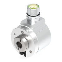
CMS582M-4096/4096 IOL DMS 14H7 KRF
TR-Electronic CMS582M-4096/4096 IOL DMS 14H7 KRF Manuals
Manuals and User Guides for TR-Electronic CMS582M-4096/4096 IOL DMS 14H7 KRF. We have
2
TR-Electronic CMS582M-4096/4096 IOL DMS 14H7 KRF manuals available for free PDF download: Assembly Instructions Manual
TR-Electronic CMS582M-4096/4096 IOL DMS 14H7 KRF Assembly Instructions Manual (253 pages)
Rotary Encoder
Brand:
TR-Electronic
| Category:
Media Converter
| Size: 56 MB
Table of Contents
Deutsch
69
Table of Contents
69
Aufwärts Gehen, Abwärts Gehen
93
Sonderbits
93
Überdrehzahl
93
Endschalter
93
Aufwärts Gegangen
94
Bewegung
94
Statischer und Dynamischer Fehler (Watchdog)
94
Parity Gerade, Fehlerparity Gerade
94
Istwerte
95
Istwert
95
Umdr/Min
95
Trwinprog Parametrierung: CM_58
96
Grundeinstellung
96
Zählrichtung
96
Skalierungsparameter
96
Messlänge (in Schritten)
96
Anzahl Umdrehungen
96
Preset Eingang
97
Preset-Wert
97
Hysterese
97
Auflösung (Anzahl der Schritte Pro Umdrehung)
97
Positionswerte
98
Ssi
98
SSI-Datenbits
98
SSI-Code
98
SSI-Ausgabe
98
SSI-Monozeit
98
Parity Gerade
99
Parity Ungerade
99
SSI-Sonderbits
99
Trwinprog Parametrierung: CE_58 bis 15 Bit Auflösung
100
Grundparameter
100
Zählrichtung
100
Skalierungsparameter
100
Messlänge in Schritten
100
Presetfreigabe
101
Anzahl Umdrehungen
101
Presetwert
101
Tannenbaum Nein
102
Ssi
102
Format
102
Anzahl Datenbits
104
Ausgabecode
104
Istwerte
104
Position
104
Trwinprog Parametrierung: CO_58 / C_H80 / C_H110
105
Zählrichtung
105
Skalierungsparameter
105
Grundparameter
105
Messlänge in Schritten
106
Umdrehungen Zähler / Umdrehungen Nenner
106
Presetwert
109
Presetfreigabe
109
Messwertanfang
109
Kein Sonderformat
110
Ssi
110
Format
110
Parity Gerade
111
Parity Ungerade
111
Toggelbit
111
Wiederholung mit 1-3 Pausentakten
112
Prüfsumme 28 nach 25-28 Datenbits
113
Anzahl Datenbits
114
Ausgabecode
114
Negative Werte
115
Monozeit
115
Inkremental (Optional)
115
Anzahl Impulse
115
Nullimpuls wenn
116
Position
117
Geschwindigkeit in Umdr/Min
117
Fehlerursachen und Abhilfen
118
English
122
Revision Index
125
Applicability
126
General Information
126
Abbreviations Used / Terminology
127
Additional Safety Instructions
128
Definition of Symbols and Instructions
128
Organizational Measures
128
Usage in Explosive Atmospheres
129
SSI Information
130
Basic Rules
131
Installation / Preparation for Commissioning
131
RS422 Data Transmission Technology
132
Cable Definition
133
Connection - Notes
133
Connection to the PC (Programming)
134
SSI Interface
135
Basic Parameters
136
Count Direction
136
Scaling Parameters
136
Trwinprog Parameterization: C_58, CE_58 - 13 Bit Resolution
136
Revolutions Numerator / Revolutions Denominator
137
Total Number of Steps
137
Origin Type
140
Preset Function
140
Preset Value
140
Format
141
Ssi
141
Tree Format no (Standard)
141
Tree Format Yes
142
Check Sum
143
26-Bit + Repeat
144
Negative Values
146
Number of Data Bits
146
Transmit Code
146
Cams
147
Going Up, Going down
147
Overspeed
147
Special Bits
147
Encoder and Dynamic Error (Watchdog)
148
Even Parity, Even Error Parity
148
Moving
148
Position
149
Position Value
149
Speed 1/Min
149
Basic Values
150
Counting Direction
150
Measuring Length (in Steps)
150
Revolution Count
150
Scaling Parameters
150
Trwinprog Parameterization: CM_58
150
Hysteresis
151
Preset Input
151
Preset Value
151
Resolution (Number of Steps Per Revolution)
151
Position-Values
152
Ssi
152
SSI-Code
152
SSI-Databits
152
SSI-Mono-Time
152
SSI-Output
152
Parity Even
153
Parity Odd
153
SSI-Special Bits
153
Basic Parameters
154
Count Direction
154
Scaling Parameters
154
Total Number of Steps
154
Trwinprog Parameterization: CE_58 - 15 Bit Resolution
154
Number of Revolutions
155
Preset Function
155
Preset Value
155
Format
156
Ssi
156
Tree Format no
156
Tree Format Yes
157
Number of Data Bits
158
Position
158
Position Value
158
Transmit Code
158
Basic Parameters
159
Count Direction
159
Scaling Parameters
159
Trwinprog Parameterization: CO_58 / C_H80 / C_H110
159
Revolutions Numerator / Revolutions Denominator
160
Total Number of Steps
160
Origin Type
163
Preset Function
163
Preset Value
163
Format
164
No Special Format
164
Ssi
164
Parity Even
165
Parity Odd
165
Toggle Bit
165
Repeat with 1-3 Low Clocks
166
Check Sum 28 after 25-28 Data Bits
167
Number of Data Bits
168
Transmit Code
168
Incremental (Optional)
169
Mono Time
169
Negative Values
169
Number of Pulses
169
Index High When
170
Position
171
Position Value
171
Speed 1/Min
171
Causes of Faults and Remedies
172
Inhaltsverzeichnis
176
Änderungs-Index
177
Allgemeines
178
Geltungsbereich
178
Verwendete Abkürzungen / Begriffe
179
Einsatz in Explosionsfähigen Atmosphären
180
Symbol- und Hinweis-Definition
180
Zusätzliche Sicherheitshinweise
180
SSI Informationen
181
Grundsätzliche Regeln
182
Installation / Inbetriebnahmevorbereitung
182
RS422 Übertragungstechnik
183
Anschluss - Hinweise
184
Kabelspezifikation
184
Anbindung an den PC (Programmierung)
185
V/R-Eingang (Optional)
186
SSI Schnittstelle
187
Grundparameter
188
Parametrierung über Trwinprog
188
Skalierungsparameter
188
Zählrichtung
188
Messlänge in Schritten
189
Umdrehungen Zähler / Umdrehungen Nenner
189
Messwertanfang
192
Presetfreigabe
192
Presetwert
192
Anzahl Datenbits
193
Code-Format
193
Format
193
Kein Sonderformat
193
Monozeit
193
Ssi
193
Prüfsumme
194
Bit Wiederholung
195
Negative Werte
197
Endschalter
198
Endschalter Ein/Aus
198
Position
198
Überdrehzahl 1/Min
198
Aufwärts Gegangen
199
Aufwärts Gehen, Abwärts Gehen
199
Bewegung
199
Endschalter
199
SSI-Sonderbits
199
Überdrehzahl
199
Parity Gerade, Fehlerparity Gerade
200
Statischer und Dynamischer Fehler (Watchdog)
200
Togglebit
200
Anzahl Impulse
201
Einheit
201
Geschwindigkeit
201
Inkremental (Optional)
201
Nullimpulsverknüpfung
202
Phase
202
Set K0
203
Signalpegel
203
Fehlerursachen und Abhilfen
204
Revision Index
209
Applicability
210
General Information
210
Abbreviations Used / Terminology
211
Additional Safety Instructions
212
Definition of Symbols and Instructions
212
Usage in Explosive Atmospheres
212
SSI Information
213
Basic Rules
214
Installation / Preparation for Commissioning
214
RS422 Data Transmission Technology
215
Cable Definition
216
Connection - Notes
216
Connection to the PC (Programming)
217
F/B Input (Optional)
218
SSI Interface
219
Basic Parameters
220
Count Direction
220
Parameterization Via Trwinprog
220
Scaling Parameters
220
Number of Revolutions - Numerator / - Divisor
221
Total Number of Steps
221
Origin Type
224
Preset Function
224
Preset Value
224
Format
225
No Special Format
225
Number of Data Bits
225
Ssi
225
SSI-Mono-Time
225
Transmit Code
225
Check Sum
226
26-Bit + Repeat
227
Negative Values
229
Cams
230
Cams On/Off
230
Overspeed 1/Min
230
Position
230
Cams
231
Going Up, Going down
231
Moving
231
Overspeed
231
SSI Special Bit
231
Encoder and Dynamic Error (Watchdog)
232
Even Parity, Even Error Parity
232
Toggle Bit
232
Incremental (Optional)
233
Number of Pulses
233
Speed
233
Unit
233
Phase
234
Set K0
235
Signal Level
235
Causes of Faults and Remedies
236
Advertisement
TR-Electronic CMS582M-4096/4096 IOL DMS 14H7 KRF Assembly Instructions Manual (164 pages)
Rotary Encoder
Brand:
TR-Electronic
| Category:
Media Converter
| Size: 52 MB
Table of Contents
Deutsch
69
Table of Contents
69
Index 0X0052: Velocity Factor
89
Index 0X0064: Speed Observation Control
90
Speed Observation Grenzwerte
90
Index 0X0065: Speed Observation Lower Limit
91
Index 0X0066: Speed Observation Upper Limit
91
Index 0X0067: Speed Observation Delay
91
Inkremental-Ausgabe (Optional)
92
Index 0X0078: Inkremental-Phasenlage
92
Index 0X0079: Inkremental-Anzahl Impulse
92
Index 0X007A: Inkremental-K0 Verhalten
93
Index 0X007B: Inkremental-Pegel
93
Index 0X0082: SSI-Ausgabecode
94
SSI-Ausgabe (Optional)
94
Index 0X007D: Inkremental-K0 Setzen
94
Index 0X007C: Inkremental-K0 Länge
94
Index 0X0083: SSI-Anzahl Datenbits
95
Index 0X0084: SSI-Monozeit
95
Index 0X0085: SSI-Ausgangsdaten
95
Index 0X0086: SSI-Sonderbit
95
Preset über Externe Eingänge (Optional)
96
Index 0X008C: Presetwert 1
96
Index 0X008D: Presetwert 2
96
System-Kommandos (Index 0X0002)
97
Set Parameter - Funktion, Kommando 0Xaa
97
Set Position - Funktion, Kommando 0Xa0
97
Auslieferungszustand Wiederherstellen - Funktion, Kommando 0X82
98
Mess-System mit Zwei Status-Leds
99
Optische Anzeigen
99
Störungsbeseitigung und Diagnosemöglichkeiten
99
Mess-System mit einer Status-LED
100
Fehlerzähler (Index 0X0020)
100
Gerätestatus (Index 0X0024)
100
Ausführlicher Gerätestatus (Index 0X0025)
101
Diagnose Betriebsstunden (Index 0X006E)
102
ISDU-Fehlertypen
103
Prozessdaten - Status
104
Sonstige Störungen
104
Austauschen des Mess-Systems
105
English
108
Contents
108
Revision Index
110
Applicability
111
General Information
111
Abbreviations Used / Terminology
112
References
112
Additional Instructions for Proper Use
113
Additional Safety Instructions
113
Definition of Symbols and Instructions
113
Optional Interface Variants
114
Usage in Explosive Atmospheres
114
IO-Link Information
115
Basic Rules
116
Installation
116
IO-Link
117
Connection - Notes
118
Device Profile / Function Classes
118
Commissioning
119
Device Identification
119
IO-Link Device Description File (IODD)
119
Process Input Data
120
Starting up on the IO-Link - System
120
Process Output Data
121
Status Display
121
Index 0X0010 - 0X0018: Identification Parameters
122
Parameterization
122
Index 0X0043: DI/DO Select Functions
123
Index 0X0044: DI Preset Value
123
Index 0X00Cb: Second Interface
123
Set Parameters
123
Index 0X0045: Count Direction
124
Index 0X0046: Position
124
Index 0X0047-0X0049: Scaling Parameters
125
Index 0X0050: Velocity Unit
128
Index 0X0051: Velocity Integration Time
129
Index 0X0052: Velocity Factor
129
Index 0X0064: Speed Observation Control
130
Speed Observation Limits
130
Index 0X0065: Speed Observation Lower Limit
131
Index 0X0066: Speed Observation Upper Limit
131
Index 0X0067: Speed Observation Delay
131
Incremental Output (Optional)
132
Index 0X0078: Incremental Output - Phase
132
Index 0X0079: Incremental Output - Pulses
132
Index 0X007A: Incremental Output - K0-Condition
133
Index 0X007B: Incremental Output - Level
133
Index 0X007C: Incremental Output - K0 Length
134
Index 0X007D: Incremental Output - Set K0
134
Index 0X0082: SSI Output - Code
134
SSI Output (Optional)
134
Index 0X0083: SSI Output - Number of Data-Bits
135
Index 0X0084: SSI Output - Mono Timer
135
Index 0X0085: SSI Output - Data
135
Index 0X0086: SSI Output - Special Bit
135
Index 0X008C: Preset-Input Value 1
136
Index 0X008D: Preset-Input Value 2
136
Preset Via External Inputs (Optional)
136
Set Parameter - Function, Command 0Xaa
137
Set Position - Function, Command 0Xa0
137
System Commands (Index 0X0002)
137
Restore Factory Settings - Function, Command 0X82
138
Measuring System with Two Status Leds
139
Optical Displays
139
Troubleshooting and Diagnosis Options
139
Device Status (Index 0X0024)
140
Error Count (Index 0X0020)
140
Measuring System with One Status LED
140
Detailed Device Status (Index 0X0025)
141
Diag. Operating Hours (Index 0X006E)
142
ISDU Error Types
143
Other Faults
144
Process Data - Status
144
Replacing the Measuring System
145
Advertisement
Related Products
TR-Electronic CMS582M 8192/4096 ETC DMS 12H7 KRF
TR-Electronic CMS582M-8192/4096 SSI DMS 12H7 KRF
TR-Electronic CMS-36
TR Electronic CMS-58
TR-Electronic CMS-65
TR-Electronic CM*-36 Series
TR Electronic CMV-58
TR Electronic CMK-58
TR-Electronic CMW582M 8192 PB SLG ME 2M Series
TR-Electronic CMW582M-00003
TR-Electronic Categories
Media Converter
Transducer
Measuring Instruments
Enclosure
DC Drives
More TR-Electronic Manuals
Login
Sign In
OR
Sign in with Facebook
Sign in with Google
Upload manual
Upload from disk
Upload from URL