Sign In
Upload
Manuals
Brands
TIL Manuals
Transceiver
TDFM-136B
TIL TDFM-136B Manuals
Manuals and User Guides for TIL TDFM-136B. We have
3
TIL TDFM-136B manuals available for free PDF download: Operating Instructions Manual, Installation Instructions Manual, Quick Reference Manual
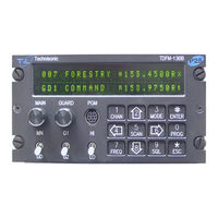
TIL TDFM-136B Operating Instructions Manual (75 pages)
VHF/FM DIGITAL AIRBORNE TRANSCEIVER
Brand:
TIL
| Category:
Transceiver
| Size: 1 MB
Table of Contents
Operating Instructions
1
Table of Contents
5
Section1
11
Controls and Display
11
Front Panel Layout and Controls
11
Figure 1-1. the TDFM-136 Front Panel Showing Control & Display Features
11
Channel Parameter Display
12
Figure 1-2. the TDFM-136 Display - Unique Parameters Highlighted
12
Figure 1-3. the TDFM-136 Display - Common Channel Parameters Highlighted
12
Transceiver Basic Operation
13
Selecting the Active Channel - Main or Guard
13
Figure 1-4. the Active Channel Display and Control Points
13
Selecting a Main Channel Memory
14
Figure 1-5. Control Points for Selecting an Active Memory for the MAIN Channel
14
About Commands
15
Command Levels
15
Figure 1-6. the Screen Showing 'Level 3" in the Command Level Display Position
15
Command Types
16
Command Groups
16
Command Reference
16
Section 2
17
Channel Operating Parameters
17
Memory Parameters
17
Editing Channel Operating Parameters
17
Figure 2-1. the User Screen to Edit the Main Frequency
18
Figure 2-2. the User Screen to Edit the Guard Frequency
18
Figure 2-3. the User Screen to Edit the Main Frequency for Receive
19
Figure 2-4. the User Screen to Edit the Main Frequency for Transmit
19
The Frequency Parameter
19
Figure 2-5. the User Screen to Edit the Main Operating Mode
20
Operating Modes
20
Table 2-1. Transceiver Operating Modes
20
Squelch Modes
21
Table 2-2. Receive and Transmit Squelch Modes
21
Figure 2-6. the Screen to Edit the Main Squelch Mode for Receive
22
Figure 2-7. the Noise Squelch Edit Screen
23
Figure 2-8. the Screen to Edit the Main Squelch Mode for Transmit
23
Figure 2-9. the CTCSS Tone Squelch Edit Screen
23
Figure 2-10. the DCS Code Squelch Edit Screen
24
Figure 2-11. the Digital NAC Squelch Edit Screen
24
Figure 2-12. the Digital Talkgroup Squelch Edit Screen
25
Figure 2-13. the Digital ID Call Squelch Edit Screen
25
ID Call Operation
25
Scan and Multi-Mode Operation
26
Scan Operation
26
Figure 2-14. the Set Unit ID Edit Screen
26
Multi-Mode Operation
27
Controlling User Access
28
Control Access to Command Levels
28
Figure 2-15. Identifying Graphic for Primary Channel with Shadows
28
Figure 2-16. Identifying Graphic for Shadow Channel
28
Set Command Permissions
29
Figure 2-17. the Screen to Enter a Password for Restricted Level Access
29
Figure 2-18. the Screen to Set the Maintenance Password
29
Figure 2-19. the Screen to Edit the Level 1 Permissions
30
Table 2-3. Permission Applicability by Command and Level
30
Control Access to Squelch Modes
31
Control Editing of Memories
31
Figure 2-20. the Screen Showing Mode Select Restrictions for Analog Receive
31
Figure 2-21. the Screen for Enabling/Disabling Edit of a Specific Memory
31
Table 2-4. Squelch Mode Restrictions
31
Control Display of Frequency Information
32
Figure 2-22. the Error Screen on Trying to Edit a Disabled Memory.l
32
Figure 2-23. the Screen for Enabling/Disabling Frequency Display for a Specific Memory
32
Figure 2-24. the Screen Showing Memory with Frequency Display Disabled
32
Encrypted Operation
33
Loading Encryption Keys
33
Assign Keytag to Encryption Keys
33
Figure 2-25. the Screen to Select the SLN to Assign the Keytag to
33
Assign Key by Keytag to Memory
34
Figure 2-26. the Screen to Edit the Keytag
34
Figure 2-27. the Screen to Assign Another Keytag or Exit
34
Figure 2-28. Select the Main Memory to Assign the Key to
35
Figure 2-29. Select the Keytag to Assign to the Memory
35
Figure 2-30. Select Decrypt on any Key or Assigned Key
35
Enable/Disable Encrypted Operation
36
Figure 2-31. the Screen to Assign Another Key or Exit
36
Figure 2-32. the Analog Memory Encryption Error Screen
36
Figure 2-33. the Error Screen for no Encryption Key Assigned
36
Figure 2-34. the Encryption Enabled for Main Memory Screen
36
Table 3-1. Command Level Reference
37
Operator Level 1 Commands
38
Select the Operating Memory for the Main Channel
38
Increase Display Brightness
38
Edit Channel Operating Mode
38
Figure 3-1. the User Screen to Enter a Memory Number
38
Figure 3-2. the User Screen to Edit the Operating Mode
38
Scroll Backwards through Available Memories
39
Start/Stop Scan
39
Figure 3-3. Trying to Start Scan on a Channel with Scan Disabled
39
Figure 3-4. Start Scan on a Channel with Scan Enabled
39
Table 3-2. Transceiver Operating Modes
39
Edit Channel Operating Frequency
40
Figure 3-5. the User Screen to Edit the Main Frequency
40
Scroll Backwards through Available Memories
40
Decrease Display Brightness
41
Edit Channel Squelch Mode
41
Figure 3-6. Editing the Squelch Mode
41
Figure 3-7. Editing the Noise Squelch Value
41
Table 3-3. Receive and Transmit Squelch Modes
41
Figure 3-10. Editing the P25 Talkgroup Value
42
Figure 3-8. Selecting the CTCSS Tone Value
42
Figure 3-9. Selecting the DCS Code Value
42
Figure 3-11. Editing the P25 NAC Value
43
Figure 3-12. Editing the P25 ID Call Value
43
Command Level up
44
Erase Encryption Keys
44
Toggle Memory: Current/Home
44
Toggle Talk Around
44
Section 3
37
Operator Level 2 Commands
44
Create/Edit All Channel Information
45
Copy Guard to Main
46
Lock Keypad
46
Not Used
46
Edit Scan List & Enable/Disable Scan
46
Edit Memory Text Description
47
Figure 3-13. the Screen to Enter a Scan List or Enable/Disable Scan
47
Figure 3-14. the Screen Showing Scan Enabled for this Memory
47
Figure 3-15. Editing the Text Description
47
Create Shadow Memory
48
Figure 3-16. Entering a Primary Memory for the Shadow Channel
48
Figure 3-17. Entering a Shadow Channel Memory Number
48
Table 3-4. Extra Characters for Text Edit
48
Copy Main to Guard
49
Encryption ON/OFF
49
Figure 3-18. Edit the Shadow Memory Parameter - Text
49
Figure 3-19. the Encryption Enabled for Main
49
Command Level up
50
Command Level down
50
L2-#. Not Used
50
Operator Level 3 Commands
50
Select Boot Channel
50
Figure 3-20. Selecting Main Channel Boot Memory
50
Assign Key by Keytag
51
Figure 3-21. Selecting the Memory to Assign the Key to
51
Figure 3-22. Selecting the Keytag to Assign to the Memory
51
Figure 3-23. Selecting the Decrypt Option: any Key or Assigned Key
51
Display Firmware Release and Version Information
52
Figure 3-24. Screen to Assign Another Key or Exit
52
Figure 3-25. Selecting Edit Mode
52
Figure 3-26. Showing the Code Release Information
52
Edit Scan Parameters
53
Figure 2-27. Select the Scan Revert Mode
53
Figure 2-28. Set the Scan Reply Timer Value
53
Configure PTT Timer
54
Figure 3-29. Set the Scan Monitor Timer Value
54
Figure 3-30. Set the Scan Delay Timer Value
54
Figure 3-31. Set the PTT Timer Value
54
Side Tone Audio Level Adjust
55
PC Data Upload/Download
55
Figure 3-32. Set the Side Tone Audio Level
55
Figure 3-33. Upload/Download Memory Data To/From the PC
55
Display Channel Squelch Parameters
56
Command Level up
56
Command Level down
56
L3-# Not Used
56
Figure 3-34. Display of the Receive Squelch Parameter Values
56
Figure 3-35. Display of the Transmit Squelch Parameter Values
56
Maintenance Commands (Level 4)
57
Set Default Record
57
Table 3-5. the Channel Template Factory Defaults
57
Set Restricted Level Access Mode
58
Set Command Permissions
58
Figure 3-36. Select the Access Mode from a List
58
Figure 3-37. Edit the Level 1 Permissions
58
Figure 2-38. Edit the Level 2 Permissions
58
Figure 3-39. Edit the Level 3 Permissions
58
Set Memory Edit
59
Figure 3-40. Enable/Disable Edit of a Specific Memory
59
Table 3-6. Permission Applicability Wrt Command Levels
59
L4-5. Not Used
60
L4-6. Not Used
60
Set Frequency Display
60
Assign Keytags to Encryption Keys
60
Figure 3-41. the Frequency Display Enable/Disable Screen
60
Figure 3-42. a Memory with Frequency Display Disabled
60
Figure 3-43. Step through Available Keys by SLN
61
Figure 3-44. the Screen to Edit the Keytag
61
Figure 3-45. the Screen to Assign Another Keytag or Exit
61
Set Squelch Restrictions
62
Figure 3-46. the Screen to Set Available Squelch Modes for Analog Receive
62
Table 3-7 Squelch Modes that Can be Restricted
62
Command Level up
63
Command Level down
63
L4-# Not Used
63
Figure 3-47. the Screen to Restrict Editing of the Noise Squelch Value
63
Figure 3-48. the Screen to Restrict Available CTCSS Tones
63
Figure 3-49. Restrict Available DCS Codes
63
Supervisor Commands (Level 5)
64
L5-1 Not Used
64
L5-2 Not Used
64
L5-3 Not Used
64
Re-Set Database to Factory Defaults
64
Figure 3-50. Erase and Re-Program to Factory Defaults
64
L5-5 Not Used
65
Transparent Mode
65
Edit Passwords
65
Figure 3-51. Transparent Mode
65
Figure 3-52. Edit Maintenance Password
65
Run Bootloader
66
Set Unit ID (UID)
66
Figure 3-53. Edit Supervisor Password
66
Figure 3-54. the Bootloader Screen
66
Figure 3-55. Set Unit ID Number (Screen for Main Shown)
66
L5-0 Not Used
67
Command Level down
67
L5-# Not Used
67
Section 4
69
Appendix A. Installing the Jumper for Restricted Level Access
69
Figure 4-1. the Screw Positions to Remove the Left Hand Side Panel
69
Figure 4-2. the Shunt Position to Enable Restricted Level Access
69
Appendix B. CTCSS Tone and DCS Code Tables
70
Table 4-1. CTCSS Tones
70
Table 4-2. DCS Codes
70
Appendix C. Programming Channel Data Using TDP and a PC
71
Figure 4-3. the Communicate with PC Command Screen
71
Figure 4-4. the TDP-136 Radio Programming Software Window
71
Table 4-3. Valid Frequency Pattern
73
Appendix D. 2.5 Khz & 6.25 Khz Valid Frequencies
74
Appendix E. Default Tables
74
Table 4-4. Memory Template Factory Defaults
74
Table 4-5. Configuration Parameter Default Values
74
Table 4-6. Scan Parameter Default Values
74
Table 4-7. Unit Identification (UID) Default Values
74
Table 4-8. Restricted Level Password Default Values
74
Advertisement
TIL TDFM-136B Installation Instructions Manual (31 pages)
VHF/FM DIGITAL AIRBORNE TRANSCEIVER
Brand:
TIL
| Category:
Transceiver
| Size: 1 MB
Table of Contents
Installation Instructions
1
Table of Contents
6
Introduction
8
Description
8
Purpose of Equipment
8
Model Variation
9
Table 1-1. TDFM-136B - Model Variation
9
Technical Characteristics
9
Table 1-2. TDFM-136B - General Characteristics
9
Table 1-3. TDFM-136B - Operational Characteristics
10
Table 1-4. TDFM-136B - Receiver Characteristics - Main and Guard
10
Certification Summary
11
Table 1-5. TDFM-136B - Transmitter Characteristics
11
Table 1-6. TDFM-136B - Environmental Testing Summary
11
Equipment Packing Log
12
Transceiver Installation
12
Installation Kit - Contents
12
Antenna Installation
12
Figure 2-1. Transceiver Mounted View of the 15 Pin Connector
13
Table 3-1. TDFM-136B - Rear Connector Pin Assignments
13
Installation - Pin Locations and Connections
13
Physical Dimensions
15
Figure 2-3. Outline Drawing for TDFM-136B Transceiver
15
Wiring Instructions
16
Main Power +28VDC
16
Main Ground
16
PTT (Ground Keying)
16
Front Panel Back Lighting
16
Audio Outputs (600 Ohms and 4 0Hms)
16
Audio Output Ground
16
MIC Signal Input
16
Memory Up/Memory down
16
Data Input/Output
16
Power Jumper
17
Transmitter Side Tone Level Adjustment
17
Main and Guard Noise Squelch Adjustment
17
Figure 2-4. Control Points for the TDFM-136B MCU Board
18
Reference Layouts
18
Section 3 - Appendices
20
Appendix Actcss TONE TABLES and DCS CODE TABLES
20
Appendix B - POST INSTALLATION EMI TEST INSTRUCTIONS
21
Purpose
21
Test Conditions
21
Methodology
21
Results
22
Procedure
23
Appendix C - WARRANTY INFORMATION
31
TIL TDFM-136B Quick Reference Manual (2 pages)
Brand:
TIL
| Category:
Transceiver
| Size: 0 MB
Table of Contents
Quick Reference Guide
1
LED Channel Squelch Indicators
1
Channel Parameter Display
1
MAIN Multi-Function Rotary Encoder
1
GUARD Multi-Function Rotary Encoder
1
Data Port
1
MN/GD (Toggle Switch)
1
G1/G1 (Toggle Switch)
1
HI/LO (Toggle Switch)
1
KEYPAD (12 Keys) – Command Level 1 Functions
1
Command Level 2 Functions
2
Command Level 3 Functions
2
Notes
2
Advertisement
Advertisement
Related Products
Til TDFM-136
TIL TDFM-9100
TIL TDFM-7000
TIL TDFM-9200
TIL TDFM-9000
TIL TDFM-7300-3
TIL TDFM-136A
TIL TDFM-7300
TIL TDFM-7300-2
TIL TDFM-9300
TIL Categories
Transceiver
Control Unit
Remote Control
Switch
Radio
More TIL Manuals
Login
Sign In
OR
Sign in with Facebook
Sign in with Google
Upload manual
Upload from disk
Upload from URL