Sign In
Upload
Manuals
Brands
Thermal Dynamics Manuals
Welding System
AUTO-CUT 30 O2
Thermal Dynamics AUTO-CUT 30 O2 Manuals
Manuals and User Guides for Thermal Dynamics AUTO-CUT 30 O2. We have
1
Thermal Dynamics AUTO-CUT 30 O2 manual available for free PDF download: Operating Manual
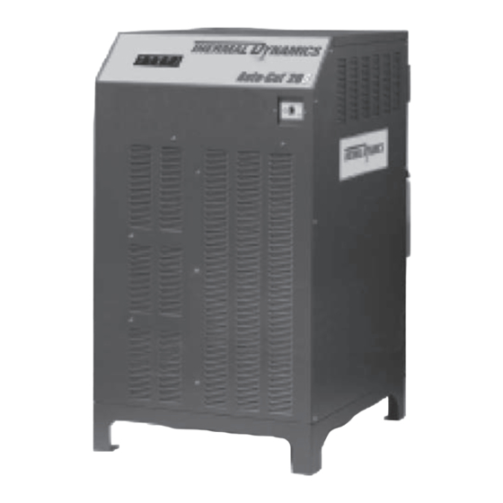
Thermal Dynamics AUTO-CUT 30 O2 Operating Manual (148 pages)
PLASMA CUTTING SYSTEM
Brand:
Thermal Dynamics
| Category:
Welding System
| Size: 9 MB
Table of Contents
Table of Contents
5
General Information
9
Notes, Cautions and Warnings
9
Important Safety Precautions
9
Publications
10
Note, Attention Et Avertissement
11
Precautions de Securite Importantes
11
Documents de Reference
13
Declaration of Conformity
14
Statement of Warranty
15
Section 2: Specifications
17
General Description of the System
17
Plasma Power Supply
17
Remote Arc Starter
17
Gas Control Module
17
Conventional Plasma Cutting Torch
17
Specifications & Electrical Requirements
18
System Layout
18
Power Supply Dimensions
19
Power Supply Rear Panel Features
20
Gas Specifications
21
Gas Applications
21
XTTM-301 Torch Specifications
22
Section 3: Installation
25
Installation Requirements
25
System Layout
26
Cables & Leads Identification
27
Lift the Power Supply
28
Primary Power Connections
29
Ground Connections
34
Connect Work Cable and Pilot and Negative / Torch Leads
36
Connect Coolant Leads
37
Connect Control Cables for CNC, Remote Arc Starter, and GCM
38
Connect Fiber Optic Cable to CCM
39
Set Switches on the Command - Control Module
40
Height Control Connections
42
Install Gas Control Module
43
Connect Fiber Optic Cable to Gas Control Module
45
Connect Control, Input, and Outputs to Gas Control Module
47
Install Remote Arc Starter
48
Install Torch Valve
57
Prepare the Torch Head
58
Connect Torch
59
Install Consumable Torch Parts
61
Install Coolant
65
Section 4: Operation
69
Power Supply Control Panel
69
Start-Up Sequence
70
Gas Control Module Operation
71
Gas Control Sequence of Operation
75
Gas Selection
78
Power Supply Status Codes
80
Remote Arc Starter: Service Chart
84
Remote Arc Starter: Spark Gap Adjustment
85
Section 5: Maintenance
87
General Maintenance Checks
87
External Coolant Filter Cleaning Procedure
87
Internal Coolant Filter Cleaning Procedure
88
Coolant Replacement Procedure
88
Section 6: Replacement Assemblies & Parts
89
Replacement Power Supply
89
Recommended Gas Supply Hose
90
Power Supply External Replacement Parts
93
Power Supply Replacement Parts - Right Side
94
Power Supply Replacement Parts - Right Side
95
Power Supply Replacement Parts - Front Panel
96
Power Supply Replacement Parts - Right Side
97
Power Supply Replacement Parts - Rear Panel
98
Power Supply Replacement Parts - Right Side
99
Power Supply Replacement Parts
100
Power Supply Replacement Parts - Right Side
101
Power Supply Replacement Parts - Left Side
102
Power Supply Replacement Parts - Left Side
103
Power Supply Replacement Parts - Right Side
104
Power Supply Replacement Parts - Right Side
105
Replacement Parts
106
Gas Control Module (GCM-2000) Replacement Parts
108
Torch Valve Assembly Replacement Parts
110
Remote Arc Starter (RAS-1000) Replacement Parts
111
Remote Arc Starter (RAS-1000) Replacement Parts
112
Torch Maintenance
113
Consumable Removal
113
Section 7: Torch Maintenance
113
O-Ring Lubrication
114
Parts Wear
115
Coolant Leak Trouble-Shooting
116
APPENDIX 1: Remote Arc Starter Schematic
117
APPENDIX 2: Gas Control and Torch Valve Schematic
118
APPENDIX 3: Gas Control Module Plumbing Diagram
120
APPENDIX 4: Gas Control Module PCB Layout
121
APPENDIX 5: CCM Input / Output PCB Layout
122
APPENDIX 6: CNC - Control Module PCB Connections
123
APPENDIX 7: CNC - Control Module PCB Connections
125
CNC Functions
126
CNC Input / Output Descriptions
127
Simplified CNC Circuit
128
APPENDIX 8: Schematic, 230-460V Unit
130
APPENDIX 8: Schematic, 230-460V Unit Cont
132
APPENDIX 9: Schematic, CCC 400V Unit
134
APPENDIX 9: Schematic, CCC 400V Unit Cont
136
APPENDIX 10: Schematic, CE 400V Unit
138
APPENDIX 10: Schematic, CE 400V Unit Cont
140
APPENDIX 11: Schematic, CSA 600V Unit
142
APPENDIX 11: Schematic, CSA 600V Unit Cont
144
APPENDIX 12: Publication History
146
Advertisement
Advertisement
Related Products
Thermal Dynamics 35C
Thermal Dynamics CUTMASTER 39
Thermal Dynamics 38 Cutmaster
Thermal Dynamics 35C DRAG-GUN PLUS
Thermal Dynamics cutskill 35A
Thermal Dynamics Ultra-Cut 300 XT
Thermal Dynamics Ultra-cut 300
Thermal Dynamics AUTO-CUT 300 XT
Thermal Dynamics MERLIN 3000
Thermal Dynamics CUTMASTER 35mm
Thermal Dynamics Categories
Welding System
Power Supply
Cutter
Controller
Flashlight
More Thermal Dynamics Manuals
Login
Sign In
OR
Sign in with Facebook
Sign in with Google
Upload manual
Upload from disk
Upload from URL