Sign In
Upload
Manuals
Brands
Texas Instruments Manuals
Motherboard
TPS7H4010EVM
Texas Instruments TPS7H4010EVM Manuals
Manuals and User Guides for Texas Instruments TPS7H4010EVM. We have
1
Texas Instruments TPS7H4010EVM manual available for free PDF download: User Manual
Texas Instruments TPS7H4010EVM User Manual (32 pages)
Brand:
Texas Instruments
| Category:
Motherboard
| Size: 4 MB
Table of Contents
Table of Contents
1
1 Introduction
3
TPS7H4010 Space Enhanced Plastic Evaluation Module
3
TPS7H4010-SEP Synchronous Step-Down Voltage Converter
3
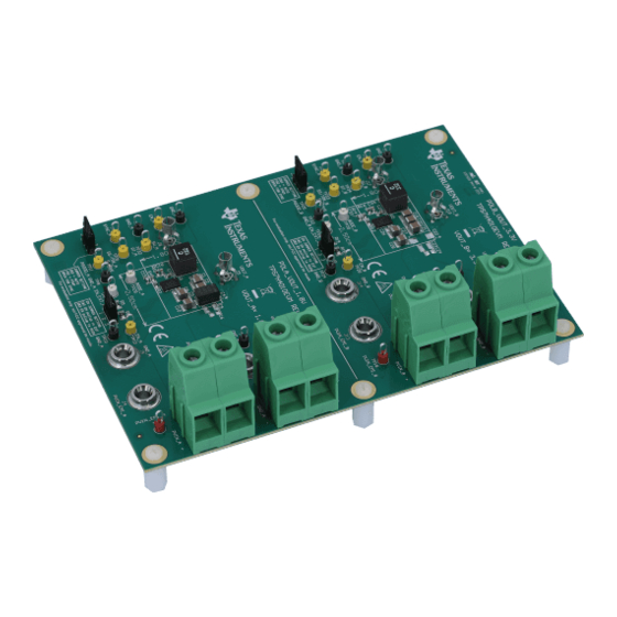
Figure 1-1. TPS7H4010EVM
3
Table 1-1. Device and Package Configurations
3
TPS7H4010-SEP Evaluation Module
4
Figure 1-2. TPS7H4010-SEP Pin Configuration (30-Pin WQFN Package Top View)
4
Figure 1-3. TPS7H4010-SEP Schematic
4
Table 1-2. Converter Circuit Variants
4
Figure 1-4. TPS7H4010-SEP Package
5
2 Quick Start
6
3 Detailed Descriptions
7
4 Schematic
10
Figure 4-1. TPS7H4010EVM PVIN=5 V, VOUT=1.8 V Schematic
10
Figure 4-2. TPS7H4010EVM PVIN=12 V, VOUT=3.3 V Schematic
11
5 Board Layout
12
Figure 5-1. Top Layer and Silkscreen Layer
12
Figure 5-2. Top Layer Routing
13
Figure 5-3. MID-Layer 1 Ground Plane
14
Figure 5-4. MID-Layer 2 Routing
15
Figure 5-5. Bottom Layer Routing
16
6 Bill of Materials
17
Table 6-1. TPS7H4010EVM BOM
17
7 TPS7H4010EVM Test Data
19
TPS7H4010EVM PVIN=5 V, VOUT=1.8 V, FSW=500 Khz
19
Figure 7-1. PVIN=5 V, VOUT=1.8 V, FSW=500 Khz: VOUT Vs IOUT
19
Figure 7-2. PVIN=5 V, VOUT=1.8 V, IOUT=6 A, FSW=500 Khz: Loop Response
20
Figure 7-3. PVIN=5 V, VOUT=1.8 V, FSW=500 Khz: Transient Response to Current Step from 2 a to 6 a at 1 A/Us
20
Figure 7-4. PVIN=5 V, VOUT=1.8 V, FSW=500 Khz: Transient Response to Current Step from 6 a to 2 a at 1 A/Us
21
Figure 7-5. PVIN=5 V, VOUT=1.8 V, IOUT=6 A, FSW=500 Khz: Output Voltage Ripple
21
Figure 7-6. PVIN=5 V, VOUT=1.8 V, IOUT=6 A, FSW=500 Khz: Soft Start
22
Figure 7-7. FSW=500 Khz: Efficiency Vs IOUT
22
TPS7H4010EVM PVIN=12 V, VOUT=3.3 V, FSW=500 Khz
23
Figure 7-8. PVIN=12 V, VOUT=3.3 V, FSW=500 Khz: VOUT Vs IOUT
23
Figure 7-9. PVIN=12 V, VOUT=3.3 V, IOUT=6 A, 3 A, 1 A, FSW=500 Khz: Loop Response
24
Figure 7-10. PVIN=12 V, VOUT=3.3 V, FSW=500 Khz: Transient Response to Current Step from 2 a to 6 a at 1 A/Us
24
Figure 7-11. PVIN=12 V, VOUT=3.3 V, FSW=500 Khz: Transient Response to Current Step from 6 a to 2 a at 1 A/Us
25
Figure 7-12. PVIN=12 V, VOUT=3.3 V, IOUT= 6 A, FSW=500 Khz: Output Voltage Ripple
25
Figure 7-13. PVIN=12 V, VOUT=3.3 V, IOUT= 6 A, FSW=500 Khz: Soft Start
26
Figure 7-14. FSW=500 Khz: Efficiency Vs IOUT
26
Advertisement
Advertisement
Related Products
Texas Instruments TPS7H4002EVM-CVAL
Texas Instruments TPS7H4011-SP
Texas Instruments TPS7H4011EVM-CVAL
Texas Instruments TPS7H4003-SEP
Texas Instruments TPS7H4011QEVM-CVAL
Texas Instruments TPS7H500-SP Series
Texas Instruments TPS7H3302EVM LP085
Texas Instruments TPS7H2140-SEP
Texas Instruments TPS7H2211EVM
Texas Instruments TPS7H1101A-SP
Texas Instruments Categories
Motherboard
Control Unit
Microcontrollers
Computer Hardware
Calculator
More Texas Instruments Manuals
Login
Sign In
OR
Sign in with Facebook
Sign in with Google
Upload manual
Upload from disk
Upload from URL