Sign In
Upload
Manuals
Brands
Texas Instruments Manuals
Motherboard
TPS6503-Q1 Series
Texas Instruments TPS6503-Q1 Series Manuals
Manuals and User Guides for Texas Instruments TPS6503-Q1 Series. We have
1
Texas Instruments TPS6503-Q1 Series manual available for free PDF download: User Manual
Texas Instruments TPS6503-Q1 Series User Manual (39 pages)
Brand:
Texas Instruments
| Category:
Motherboard
| Size: 19 MB
Table of Contents
Table of Contents
1
Introduction
3
Requirements
3
Operation Instructions
3
Table 3-1. Adapter Power Source (J18)
3
Table 3-2. Dedicated LDO Supply for Adapter (J19)
3
Table 3-3. Adapter PMIC Connections
4
Table 3-4. Buck 1 Power Source (J33)
4
Table 3-5. MID-Vin (Buck1) Features
4
Table 3-6. MID-Vin (Buck1) Configurable Settings
4
Table 3-7. Buck 2 Power Source (J15)
4
Table 3-8. Buck 3 Power Source (J16)
4
Table 3-9. Low-Vin (Buck2 and Buck3) Features
5
Table 3-10. Low-Vin (Buck2 and Buck3) Configurable Settings
5
Table 3-11. PMIC LDO Power Source (J8)
5
Table 3-12. Low Noise LDO Features
5
Table 3-13. Low Noise LDO Configurable Settings
5
EVM Configurations
6
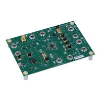
Figure 4-1. TPS650330-Q1 EVM Top View
6
Table 3-14. VIO Power Source (J8)
6
Test Points
7
Table 5-1. TPS650330-Q1 EVM Test Points
7
Graphical User Interface
8
Figure 5-1. TPS650330-Q1 EVM Test Point Locations
8
Figure 6-1. TPS650330-Q1 EVM Debugging Flow
9
Figure 6-2. Opening Serial Port Options
10
Figure 6-3. Selecting an Alternate Port
10
Figure 6-4. Tps6503Xx-Q1 GUI Home Screen
11
Figure 6-5. Tps6503Xx-Q1 GUI Block Diagram Page
12
Figure 6-6. Register Page Interfaces
12
Figure 6-7. Tps6503Xx-Q1 GUI Device Configuration Page
13
Figure 6-8. Device Selection for Generating NVM
14
Figure 6-9. Example Settings Output
14
Figure 6-10. Sequencing Overview Tab
15
Figure 6-11. Sequencing Overview Including GPIO
15
Figure 6-12. GUI Generated Timing Diagram
16
Figure 6-13. Tps6503Xx-Q1 GUI Re-Program PMIC Page
16
Figure 6-14. GUI Configuration CRC Script
17
Typical Performance Plots
18
Figure 7-1. TPS650330-Q1 Default Power up Sequence
18
Figure 7-2. TPS650330-Q1 Default Power down Sequence
18
TPS650330-Q1 EVM Schematic
21
Figure 8-1. TPS650330-Q1
21
Figure 8-2. MSP432E401Y Schematic
22
TPS650330-Q1 EVM PCB Layers
23
Figure 9-1. Top Layer
23
Figure 9-2. MID-Layer 1
24
Figure 9-3. MID-Layer 2
25
Figure 9-4. MID-Layer 3
26
Figure 9-5. MID-Layer 4
27
Figure 9-6. Bottom Layer (Mirrored)
28
TPS650330-Q1 EVM Bill of Materials
29
Table 10-1. TPS650330-Q1 EVM Bill of Materials
29
TPS650330-Q1 Silicon Revision Changes
32
Settings
32
Table 11-1. Tps65033X-Q1 Silicon Revision B0 Feature Changes
32
Revision History
33
Advertisement
Advertisement
Related Products
Texas Instruments TPS65033-Q1 Series
Texas Instruments TPS650330-Q1
Texas Instruments TPS650320-Q1
Texas Instruments TPS650350-Q1 EVM
Texas Instruments TPS65020EVM-110
Texas Instruments TPS65084x EVM
Texas Instruments TPS65023EVM
Texas Instruments TPS65023EVM-205
Texas Instruments TPS65053EVM-389
Texas Instruments TPS6507 EVM Series
Texas Instruments Categories
Motherboard
Control Unit
Microcontrollers
Computer Hardware
Calculator
More Texas Instruments Manuals
Login
Sign In
OR
Sign in with Facebook
Sign in with Google
Upload manual
Upload from disk
Upload from URL