Sign In
Upload
Manuals
Brands
Texas Instruments Manuals
Motherboard
TPS546D24SEVM-2PH
Texas Instruments TPS546D24SEVM-2PH Manuals
Manuals and User Guides for Texas Instruments TPS546D24SEVM-2PH. We have
1
Texas Instruments TPS546D24SEVM-2PH manual available for free PDF download: User Manual
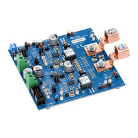
Texas Instruments TPS546D24SEVM-2PH User Manual (49 pages)
2-Phase SWIFT Step-Down Converter Evaluation Module
Brand:
Texas Instruments
| Category:
Motherboard
| Size: 4.17 MB
Table of Contents
Table of Contents
1
Description
4
Before You Begin
4
Typical Applications
4
Features
5
Electrical Performance Specifications
6
Table 2-1. TPS546D24SEVM-2PH Electrical Performance
6
Schematic
7
Figure 3-1. TPS546D24SEVM-2PH Schematic
7
Figure 3-2. TPS546D24SEVM-2PH Schematic Page 2 (U1_P1 Controller)
8
Figure 3-3. TPS546D24SEVM-2PH Schematic Page 3 (U1_P2 Follower)
9
Test Setup
10
Test and Configuration Software
10
Test Equipment
10
Tip and Barrel Measurement
11
List of Test Points, Jumpers, and Connectors
11
Figure 4-1. Tip and Barrel Measurement
11
Output
11
Table 4-1. Test Point Functions
11
Table 4-2. Jumpers
12
Table 4-3. JP2_P1 and JP2_P2 Selections
12
Table 4-4. JP7_P1 and JP7_P2 Selections
12
Table 4-5. Connector Functions
12
Evaluating Single Phase Operation
14
Evaluating Split Rail Input
14
Configuring EVM to Overdrive VDD5
14
EVM Configuration Using the Fusion GUI
15
Configuration Procedure
15
Test Procedure
16
Line and Load Regulation and Efficiency Measurement Procedure
16
Efficiency Measurement Test Points
17
Figure 7-2. Efficiency
17
Table 6-1. Test Points for Efficiency Measurements
17
Table 6-2. Test Points for Better Efficiency Measurements
17
Control Loop Gain and Phase Measurement Procedure
18
Performance Data and Typical Characteristic Curves
19
Efficiency
19
Load and Line Regulation (Measured between TP22 and TP25)
19
Figure 7-1. Efficiency
19
Figure 7-3. Load Regulation
19
OUT Measured Using TP22 and TP25
19
Figure 7-4. Line Regulation
19
Transient Response
20
Control Loop Bode Plot
20
Figure 7-5. Transient Response
20
Figure 7-6. Bode Plot at 0.8-V Output at 12 V Figure 7-7. Output Ripple with 0-A Load
20
IN , 20-A Load
20
Output Ripple
21
Figure 7-8. Output Ripple with 80-A Load
21
Power MOSFET Drain-Source Voltage
22
Control on
22
Figure 7-9. Low-Side MOSFET V
22
Figure 7-10. High-Side MOSFET V
22
Figure 7-11. Start-Up from Control, 0-A Load
23
Figure 7-12. Start-Up from Control, 80-A CC Load
23
Control off
24
Figure 7-13. Shutdown from Control, 0-A Load
24
Figure 7-14. Shutdown from Control, 20-A CC Load
24
Control on with Pre-Biased Output
25
Current Sharing between Two Phases
25
Figure 7-15. Start-Up from Control with Pre-Biased
25
Figure 7-16. Inductor Current and Switch Node Waveform, 40-A Load
25
Thermal Image
26
Figure 7-17. Thermal Image
26
EVM Assembly Drawing and PCB Layout
27
Figure 8-1. TPS546D24SEVM-2PH Top Side Component View (Top View)
27
Figure 8-2. TPS546D24SEVM-2PH Bottom Side Component View (Bottom View)
27
Figure 8-3. TPS546D24SEVM-2PH Top Copper (Top View)
27
Figure 8-4. TPS546D24SEVM-2PH Internal Layer
28
Figure 8-5. TPS546D24SEVM-2PH Internal Layer
28
Figure 8-6. TPS546D24SEVM-2PH Internal Layer 3
28
Figure 8-7. TPS546D24SEVM-2PH Internal Layer
28
Figure 8-8. TPS546D24SEVM-2PH Internal Layer 5 (Top View)
28
Figure 8-9. TPS546D24SEVM-2PH Internal Layer 6
29
Figure 8-10. TPS546D24SEVM-2PH Internal Bottom Layer (Top View)
29
Bill of Materials
30
Using the Fusion GUI
33
Opening the Fusion GUI
33
Figure 10-1. Select Device Scanning Mode
33
General Settings
34
Figure 10-2. General Settings
34
Changing ON_OFF_CONFIG
35
Figure 10-3. Configure - ON_OFF_CONFIG
35
Pop-Up for some Commands While Conversion Is Enabled
36
Figure 10-4. Pop-Up When Trying to Change FREQUENCY_SWITCH with Conversion Enabled
36
SMBALERT# Mask
37
Figure 10-5. Configure - SMBALERT # Mask
37
Device Info
38
Figure 10-6. Configure - Device Info
38
Phase Commands
39
Figure 10-7. Phase Commands
39
All Config
40
Figure 10-8. Configure - All Config
40
Pin Strapping
41
Figure 10-9. Configure - Pin Strapping
41
Figure 10-10. Monitor Screen
42
Figure 10-11. Status Screen
43
Advertisement
Advertisement
Related Products
Texas Instruments TPS54614EVM 1.8-V SWIFT
Texas Instruments TPS54673EVM-225
Texas Instruments TPS546B24AEVM-2PH
Texas Instruments SWIFT TPS54680EVM-228
Texas Instruments TPS5420EVM-175 SWIFT
Texas Instruments TPS54380EVM-001
Texas Instruments TPS54873EVM-225
Texas Instruments TPS54231
Texas Instruments TPS543620
Texas Instruments TPS54A20
Texas Instruments Categories
Motherboard
Control Unit
Microcontrollers
Computer Hardware
Calculator
More Texas Instruments Manuals
Login
Sign In
OR
Sign in with Facebook
Sign in with Google
Upload manual
Upload from disk
Upload from URL