Sign In
Upload
Manuals
Brands
Texas Instruments Manuals
Motherboard
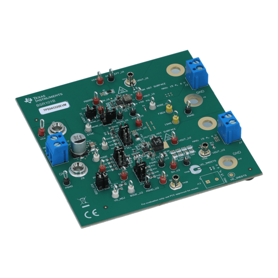
TPS543320EVM
Texas Instruments TPS543320EVM Manuals
Manuals and User Guides for Texas Instruments TPS543320EVM. We have
1
Texas Instruments TPS543320EVM manual available for free PDF download: User Manual
Texas Instruments TPS543320EVM User Manual (36 pages)
SWIFT Step-Down Converter Evaluation Module
Brand:
Texas Instruments
| Category:
Motherboard
| Size: 5 MB
Table of Contents
Table of Contents
1
Introduction
3
Background
3
Before You Begin
3
Table 1-1. Input Voltage and Output Current
3
Performance Characteristics Summary
4
Table 1-2. TPS543320EVM Small Size (U1) Performance Characteristics Summary
4
Table 1-3. TPS543320EVM High Efficiency (U2) Performance Characteristics
5
Configurations and Modifications
6
Output Voltage
6
Table 2-1. VOUT Selection
6
Switching Frequency (FSEL Pin)
7
Current Limit, Soft-Start Time, and Internal Compensation (MODE Pin)
7
Adjustable UVLO
7
Table 2-2. FSEL Selection
7
Table 2-3. MODE Selection
7
Test Setup and Results
8
Input/Output Connections
8
Table 3-1. Connectors and Jumpers
9
Table 3-2. Test Points
10
Efficiency
11
Table 3-3. Efficiency Measurement Test Points
11
Output Voltage Regulation
13
Figure 3-5. U1 Load Regulation
13
Figure 3-6. U1 Line Regulation
13
Figure 3-7. U2 Load Regulation
13
Figure 3-8. U2 Line Regulation
13
Load Transient and Loop Response
14
Figure 3-9. U1 Transient Response
14
Figure 3-10. U2 Transient Response
14
Figure 3-11. U1 Bode Plot
14
Figure 3-12. U2 Bode Plot
14
Figure 3-13. U2 Loop Gain with Different Ramp Settings
15
Figure 3-14. U2 Loop Phase with Different Ramp Settings
15
Output Voltage Ripple
16
Figure 3-15. U1 Output Ripple - no Load
16
Figure 3-16. U1 Output Ripple - 3-A Load
16
Figure 3-17. U2 Output Ripple - no Load
16
Figure 3-18. U2 Output Ripple - 3-A Load
16
Input Voltage Ripple
17
Figure 3-19. U1 Input Ripple - no Load
17
Figure 3-20. U1 Input Ripple - 3-A Load
17
Figure 3-21. U2 Input Ripple - no Load
17
Figure 3-22. U2 Input Ripple - 3-A Load
17
Synchronizing to a Clock
18
Figure 3-23. U1 and U2 Synchronized to a Clock
18
Figure 3-24. U2 Clock Synchronization Transitions
18
Start-Up and Shutdown with en
19
Figure 3-25. U2 Start-Up with en - no Load
19
Figure 3-26. U2 Shutdown with en - no Load
19
Figure 3-27. U2 Startup with en - no Load and Measuring BP5
19
Start-Up and Shutdown with VIN
20
Figure 3-28. U2 Start-Up with VIN - 1.5-A Load
20
Figure 3-29. U2 Shutdown with VIN - 1.5-A Load
20
Hiccup Current Limit
21
Figure 3-30. U2 Output Overcurrent Protection - Overload
21
Figure 3-31. U2 OCP Hiccup and Recover
21
Overvoltage Protection
22
Figure 3-32. U2 Overvoltage Protection
22
Figure 3-33. U2 OVP and Recover
22
Thermal Performance
23
Figure 3-34. U1 Thermal Performance - 3-A Load and U2 off
23
Figure 3-35. U2 Thermal Performance - 3-A Load and U1 off
23
Figure 3-36. U1 Thermal Performance - both 3-A Load
23
Figure 3-37. U2 Thermal Performance - both 3-A Load
23
Board Layout
24
Layout
24
Figure 4-1. Top-Side Composite View
24
Figure 4-2. Bottom-Side Composite View (Viewed from Bottom)
24
Schematic and Bill of Materials
25
Figure 4-3. Top Layer Layout
25
Figure 4-4. MID Layer 1 Layout
25
Figure 4-5. MID Layer
25
Figure 4-6. Bottom Layer Layout
25
Schematic
26
Figure 5-1. U1 Schematic
26
Figure 5-2. U2 Schematic
27
Bill of Materials
28
Table 5-1. TPS543320EVM Bill of Materials
28
Revision History
30
Advertisement
Advertisement
Related Products
Texas Instruments TPS54332EVM-416
Texas Instruments TPS54336AEVM-010
Texas Instruments TPS54334EVM-722
Texas Instruments TPS54331EVM-232
Texas Instruments TPS54326EVM-540
Texas Instruments TPS54386EVM
Texas Instruments TPS54380EVM-001
Texas Instruments TPS54373EVM-237
Texas Instruments TPS543820EVM
Texas Instruments TPS543620
Texas Instruments Categories
Motherboard
Control Unit
Microcontrollers
Computer Hardware
Calculator
More Texas Instruments Manuals
Login
Sign In
OR
Sign in with Facebook
Sign in with Google
Upload manual
Upload from disk
Upload from URL