Sign In
Upload
Manuals
Brands
Terex Manuals
Boom Lifts
Genie Z-60 DC
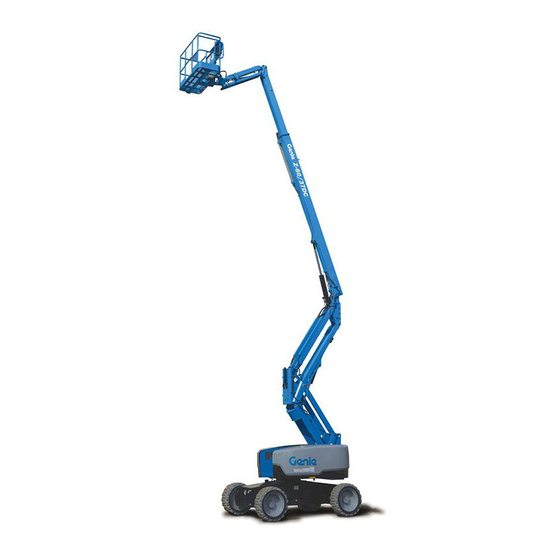
Terex Genie Z-60 DC Manuals
Manuals and User Guides for Terex Genie Z-60 DC. We have
6
Terex Genie Z-60 DC manuals available for free PDF download: Service Manual, Service And Repair Manual, Operator's Manual, Operator's Manual Supplement
Terex Genie Z-60 DC Service Manual (193 pages)
Brand:
Terex
| Category:
Lifting Systems
| Size: 5 MB
Table of Contents
Find a Manual for this Model
2
Serial Number Legend
4
Safety Rules
5
Table of Contents
7
Specifications
13
Machine Specifications
13
Performance Specifications
14
Hydraulic Oil Specifications
14
Hydraulic Component Specifications
17
Manifold Component Specifications
17
Kubota D1105 Engine Specifications
18
Machine Torque Specifications
19
Machine Component Weights
19
Hydraulic Hose and Fitting Torque Specifications
20
Torque Procedure
21
Repair Procedures
23
Introduction
23
Cailbration Process Steps
25
Platform Controls
26
How to Adjust the Joystick Threshold Setting
27
How to Adjust the Joystick Max-Out Setting
28
How to Adjust the Joystick Ramp Rate Setting
30
How to Calibrate Booms Angle Sensors
32
How to Clear the Fault History
33
Platform Components
34
Platform Leveling Slave Cylinder
34
Platform Rotator
35
Platform Overload System
36
How to Perform a Zero Load Platform Calibration
36
How to Perform a Full Load Platform Calibration
37
How to Replace the Platform Overload Load Cell
39
How to Reset Overload Recovery Message
40
Jib Boom Components
41
Jib Boom
41
Jib Boom Lift Cylinder
42
Primary Boom Components
43
Cable Track
43
How to Repair the Cable Track
44
Primary Boom
44
How to Disassemble the Primary Boom
45
Primary Boom Lift Cylinder
46
Primary Boom Extension Cylinder
47
Platform Leveling Master Cylinder
48
Secondary Boom Components
49
Secondary Boom Lift Cylinder
50
Engines
52
RPM Adjustment
52
Hydraulic Pumps
53
Function Pump
53
How to Check the Function Pump Calibration
54
Manifolds
56
Function Manifold Components
56
Valve Adjustments - Function Manifold
60
How to Adjust the Proportional Relief Valve and Hydraulic Pressure Sensor
60
How to Adjust the Platform Level up Relief Valve
61
How to Adjust the Primary Boom Extend Relief Valve
62
Jib Boom / Platform Rotate Manifold Components
63
Turntable Rotation Manifold Components
64
Oscillate Directional Valve Manifold Components
65
How to Set up the Oscillate Directional Valve
66
How to Adjust the Oscillate Reducing Valve
66
How to Test a Coil Diode
68
Turntable Rotation Components
70
Turntable Rotation Assembly
70
How to Replace the Universal Tilt Sensor
72
How to Calibrate the Universal Tilt Sensor
73
Axle Components
74
Oscillating Axle Cylinders
74
How to Remove the Steer Cylinder
75
How to Calibrate the Steer Angle Sensor
75
Battery Charger
77
Fault Codes
78
Introduction
78
Control System Fault Codes
79
Fault Codes Ground Controls
79
How to Retrieve Control System Fault Codes - Platform Controls
80
Control System Fault Codes
82
Charger Fault Codes
103
Battery Charger
103
Charger Fault Codes
104
Charger Error Codes
105
Pump Control Fault Codes
109
Pump Controller Fault Handling
109
Drive Control Fault Codes
118
Drive Controller Fault Handling
118
Navigation Menus
137
Top Menu
137
Faults Navigation Menu
138
Options Navigation Menu
139
Settings Navigation Menu
140
Advanced and Drive Navigation Menu
141
Schematics
143
Introduction
143
Electrical Symbol Legend
144
Hydraulic Symbols Legend
145
Electrical Component and Wire Color Legends
146
Kubota Engine Fuse and Relay Module
149
DC Charger Wiring (DC Option)
150
AC Input Wiring (DC Option)
151
Limit Switch/Angle Sensor Legend
152
Electrical Schematics - Options
153
Wiring Diagrams - Options [From Z60H-2548 to 2999]
154
Wiring Diagram, Options [From Z60H-2548 to 2999]
155
Electrical Schematic - Options, 4WD [From Z60H-2548 to 2999]
158
Power Cable Wiring Diagram [From Z60H-2548 to 2999]
159
Wiring Diagram - FE Models [From Z60H-3000, Z60M-1000]
162
Wiring Diagram - DC Models [From Z60H-3000, Z60M-1000]
163
Electrical Schematics
165
Electrical Schematic [From Z60H-2548 to 2999]
166
Electrical Schematic [From Z60H-2548 to 2999]
167
Ground Control Box Wiring Diagram [From Z60H-2548 to 2999]
170
Ground Control Box Wiring Diagram [From Z60H-2548 to 2999]
171
Platform Control Box Wiring Diagram [From Z60H-2548 to 2999]
174
Platform Control Box Wiring Diagram [From Z60H-2548 to 2999]
175
Electrical Schematic, PCON [From Z60H-2548 to 2999]
178
CAN BUS Wiring Diagram [From Z60H-2548 to 2999]
179
Electrical Schematic, DCON [From Z60H-3000, Z60M-1000]
182
Electrical Schematic, GCON [From Z60H-3000, Z60M-1000]
183
Electrical Schematic, PCON [From Z60H-3000, Z60M-1000]
186
Electrical Schematic, TCON [From Z60H-3000, Z60M-1000]
187
Wiring Diagram, CAN BUS [From Z60H-3000, Z60M-1000]
190
Hydraulic Schematic
192
Advertisement
Terex Genie Z-60 DC Service And Repair Manual (125 pages)
Serial Number Range from Z6016N-101 to Z6016N-599, from Z60N-600
Brand:
Terex
| Category:
Boom Lifts
| Size: 5 MB
Table of Contents
Table of Contents
7
Find a Manual for this Model
2
Serial Number Legend
4
Safety Rules
5
Table of Contents
7
Specifications
11
Machine Specifications
11
Performance Specifications
12
Hydraulic Specification
12
Hydraulic Component Specifications
15
Manifold Component Specifications
16
Kubota D1105 Engine Specifications
17
Machine Torque Specifications
18
Machine Component Weights
18
Hydraulic Hose and Fitting Torque Specifications
19
Torque Procedure
20
Repair Procedures
22
Introduction
22
Observe and Obey
22
About this Section
23
Cailbration Process Steps
24
Platform Controls
25
How to Adjust the Joystick Threshold Setting
26
How to Adjust the Joystick Max-Out Setting
27
How to Adjust the Joystick Ramp Rate Setting
30
How to Calibrate Booms Angle Sensors
31
How to Clear the Fault History
32
Platform Components
32
Platform Leveling Slave Cylinder
32
Bodily Injury Hazard. Spraying
33
Platform Rotator
34
Platform Overload System
35
How to Reset Overload Recovery Message
37
Jib Boom Components
38
Jib Boom
38
Jib Boom Lift Cylinder
39
Primary Boom Components
40
Cable Track
40
How to Repair the Cable Track
41
Primary Boom
41
How to Disassemble the Primary Boom
42
Primary Boom Lift Cylinder
43
Primary Boom Extension Cylinder
44
Platform Leveling Master Cylinder
45
Secondary Boom Components
46
Secondary Boom Lift Cylinder
47
Engines
49
RPM Adjustment
49
How to Replace the Motor Tach Sensor
49
Hydraulic Pumps
50
Function Pump
50
How to Check the Function Pump Calibration
51
Manifolds
52
Function Manifold Components
53
Valve Adjustments - Function Manifold
57
How to Adjust the Proportional Relief Valve and Hydraulic Pressure Sensor
57
How to Adjust the Platform Level up Relief Valve
58
How to Adjust the Primary Boom Extend Relief Valve
59
Jib Boom / Platform Rotate Manifold Components
60
Turntable Rotation Manifold Components
61
Oscillate Directional Valve Manifold Components
62
How to Set up the Oscillate Directional Valve
63
How to Adjust the Oscillate Reducing Valve
63
Electrocution/Burn Hazard
64
How to Test a Coil Diode
65
Turntable Rotation Components
66
Turntable Rotation Assembly
66
How to Replace the Universal Tilt Sensor
68
How to Calibrate the Universal Tilt Sensor
69
Axle Components
70
Oscillating Axle Cylinders
70
How to Remove the Steer Cylinder
71
Connections very Slowly to Allow
71
Gradually. Do Not Allow Oil to
71
How to Calibrate the Steer Angle Sensor
71
Hydraulic Oil Can Penetrate and Burn Skin. Loosen Hydraulic
71
Squirt or Spray
71
The Oil Pressure to Dissipate
71
Fault Codes
73
Introduction
73
Before Troubleshooting
73
Immediately Tag and Remove from Service a Damaged or Malfunctioning Machine
73
R Immediately Tag and Remove from Service a
73
R Read, Understand and Obey the Safety Rules
73
R Repair any Machine Damage or Malfunction
73
R Troubleshooting and Repair Procedures Shall be
73
Repair any Machine Damage or Malfunction before Operating the Machine
73
Troubleshooting and Repair Procedures Shall be Completed by a Person Trained and Qualified on the Repair of this Machine
73
Control System Fault Codes
74
Fault Codes Ground Controls
74
How to Retrieve Control System Fault Codes - Platform Controls
75
Control System Fault Codes
76
Navigation Menus
91
Faults Navigation Menu
92
Options Navigation Menu
93
Settings Navigation Menu
94
Schematics
95
Introduction
95
Electrical Symbol Legend
96
Hydraulic Symbols Legend
97
Electrical Component and Wire Color Legends
98
Kubota Engine Fuse and Relay Module
101
DC Charger Wiring (DC Option)
102
AC Input Wiring (DC Option)
103
CAN BUS Wiring Diagram - DC Models
104
Limit Switch/Angle Sensor Legend
105
Electrical Schematics - Options
107
Wiring Diagram - Options
108
Schematics - Options, 4WD, DC and FE Models
109
Power Cable Wiring Diagram
112
Hydraulic Schematics
113
Hydraulic Schematic, DC and FE Models
113
Electrical Schematics
115
Electrical Schematics, DC/FE Models
116
Ground Control Box Terminal Strip Wiring Diagram
122
Platform Control Box Wiring Diagram
123
Terex Genie Z-60 DC Operator's Manual (82 pages)
Brand:
Terex
| Category:
Boom Lifts
| Size: 5 MB
Table of Contents
Table of Contents
2
Introduction
3
Symbol and Hazard Pictorials Definitions
7
General Safety
10
Personal Safety
20
Work Area Safety
21
Legend
30
Controls
31
Inspections
39
Operating Instructions
60
Transport and Lifting Instructions
72
Maintenance
75
Specifications
79
Advertisement
Terex Genie Z-60 DC Operator's Manual (73 pages)
Brand:
Terex
| Category:
Boom Lifts
| Size: 3 MB
Table of Contents
Table of Contents
2
Introduction
3
Symbol and Hazard Pictorials Definitions
7
General Safety
10
Personal Safety
15
Work Area Safety
16
Legend
25
Controls
26
Inspections
33
Operating Instructions
50
Transport and Lifting Instructions
61
Maintenance
64
Specifications
68
Terex Genie Z-60 DC Operator's Manual (71 pages)
Brand:
Terex
| Category:
Boom Lifts
| Size: 4 MB
Table of Contents
Table of Contents
2
Introduction
3
Symbol and Hazard Pictorials Definitions
7
General Safety
10
Personal Safety
15
Work Area Safety
16
Legend
25
Controls
26
Inspections
33
Operating Instructions
50
Transport and Lifting Instructions
61
Maintenance
64
Specifications
68
Terex Genie Z-60 DC Operator's Manual Supplement (17 pages)
Brand:
Terex
| Category:
Boom Lifts
| Size: 0 MB
Table of Contents
Table of Contents
2
Introduction
2
Important Information
3
Safety Rules
5
Wind Speed Chart
7
Platform Capacity Reduction
8
Platform Capacity Reduction Charts - Imperial
11
Platform Capacity Reduction Charts - Metric
14
Advertisement
Related Products
Terex Genie Z-60DC
Terex Genie Z-60 DE
Terex Genie Z-60/37 DC
Terex Genie Z-60 FE
Terex Genie Z-60FE
Terex Z60H-2548
Terex Z60H-3000
Terex Z60M-1000
Terex Genie Z-60
Terex Z60M-1200
Terex Categories
Boom Lifts
Lifting Systems
Construction Equipment
Scissor Lifts
Compact Loader
More Terex Manuals
Login
Sign In
OR
Sign in with Facebook
Sign in with Google
Upload manual
Upload from disk
Upload from URL