Sign In
Upload
Manuals
Brands
TEREX Manuals
Boom Lifts
Genie Z-45/25 Bi-Energy
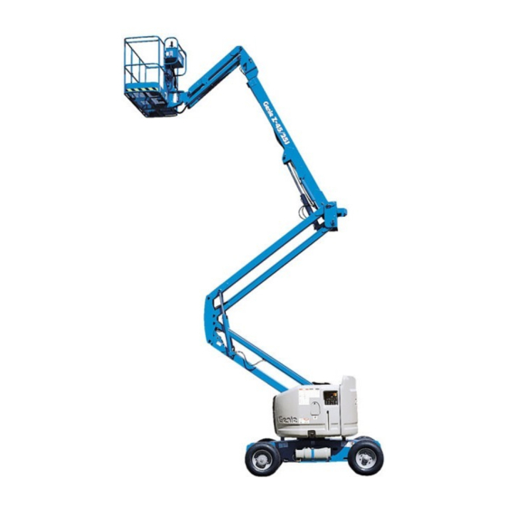
TEREX Genie Z-45/25 Bi-Energy Manuals
Manuals and User Guides for TEREX Genie Z-45/25 Bi-Energy. We have
6
TEREX Genie Z-45/25 Bi-Energy manuals available for free PDF download: Service Manual, Service And Repair Manual, Operator's Manual, Operator's Manual Supplement
TEREX Genie Z-45/25 Bi-Energy Service Manual (213 pages)
Brand:
TEREX
| Category:
Boom Lifts
| Size: 2.75 MB
Table of Contents
Introduction
2
Serial Number Information
2
Revision History
3
Serial Number Legend
5
Safety Rules
6
Personal Safety
6
Table of Contents
8
Specifications
17
Machine Specifications
17
Performance Specifications
18
Hydraulic Specifications
19
Manifold Component Specifications
20
Machine Torque Specifications
20
Generator
22
Generator Torque Specifications
22
Hydraulic Hose and Fitting Torque Specifications
23
Scheduled Maintenance Procedures
27
Pre-Delivery Preparation
29
Maintenance Inspection Report
31
Checklist a Procedures
33
Inspect the Manuals and Decals
33
Perform Pre-Operation Inspection
34
Perform Function Tests
34
Check the Generator Belts and Pulleys
35
Perform 30 Day Service
36
Perform Engine Maintenance
37
Grease the Turntable Rotation Bearing and Rotate Gear
38
Perform Engine Maintenance
38
Perform Engine Maintenance
39
Checklist B Procedures
40
Check the Radiator
40
Check the Exhaust System
40
Check the Batteries
41
Inspect the Electrical Wiring
42
Check the Tires, Wheels and Lug Nut Torque
43
Confirm the Proper Brake Configuration
44
Check the Oil Level in the Drive Hubs
44
Check and Adjust the Engine RPM
45
Test the Ground Control Override
47
Test the Platform Self-Leveling
47
Test the Engine Idle Select
48
Test the Drive Brakes
49
Test the Drive Speed - Stowed Position
49
Test the Drive Speed - Raised or Extended Position
50
Test the Alarm Package (if Equipped)
50
Check the Electrical Contactors
52
Perform Hydraulic Oil Analysis
52
Test the Emergency Power System
53
Perform Engine Maintenance
54
Checklist C Procedures
55
Perform Engine Maintenance
55
Grease the Platform Overload Mechanism (if Equipped)
55
Perform Engine Maintenance
58
Checklist D Procedures
59
Check the Primary Boom Wear Pads
59
Check the Free-Wheel Configuration
59
Replace the Drive Hub Oil
60
Replace the Hydraulic Tank Return Filter
61
Calibrate the Platform Overload System (if Equipped)
62
Check the Turntable Rotation Bearing Bolts
64
Inspect for Turntable Bearing Wear
65
Perform Engine Maintenance
67
Checklist E Procedures
68
Test or Replace the Hydraulic Oil
68
Grease the Steer Axle Wheel Bearings
69
Perform Engine Maintenance
71
Repair Procedures
73
Platform Controls
74
Controllers
74
Platform Components
76
Platform Leveling Slave Cylinder
76
Platform Rotator
77
Jib Boom Components, Z-45/25J Models
79
Jib Boom
79
Jib Boom Lift Cylinder
80
Primary Boom Components
82
Cable Track
82
Primary Boom
86
Primary Boom Lift Cylinder
89
Primary Boom Extension Cylinder
90
Platform Leveling Master Cylinder
91
Secondary Boom Components
92
Secondary Boom
93
Secondary Boom Lift Cylinders
98
Kubota Z482-E and Z482-E2B Engine
99
Timing Adjustment
99
RPM Adjustment
99
Engine Drive Pulley
99
Generator
101
Generator Pulley
101
Generator Belts
102
Generator Voltage Regulator
102
Hydraulic Pumps
105
Auxiliary Pump
105
Function Pump
106
Manifolds
108
Function Manifold Components
108
Valve Adjustments - Function Manifold
110
Jib Boom / Platform Rotate Manifold Components
111
Turntable Rotation Manifold Components
112
Valve Coils
113
Turntable Rotation Components
115
Turntable Rotation Assembly
115
Motor Controller
117
Fault Codes
119
Fault Code Chart
121
Electrical Symbols Legend
126
Hydraulic Symbols Legend
127
Electrical Schematics - ANSI / CSA
129
Electrical Schematic (ANSI / CSA)
129
(From Serial Number Z452510A-39314 to Z452513A-45734)
129
(From Serial Number Z452510A-39314 to Z452513A-45734)
130
Electrical Schematic (ANSI / CSA from Serial Number Z452510A-39314 to Z452513A-45734)
130
Ground Control Box Terminal Strip Wiring Diagram (ANSI / CSA)
133
(From Serial Number Z452510A-39314 to Z452513A-45734)
133
Ground Control Box Terminal Strip Wiring Diagram (ANSI / CSA from Serial Number Z452510A-39314 to Z452513A-45734)
134
Ground Control Box Switch Panel Wiring Diagram (ANSI / CSA from Serial Number Z452510A-39314 to Z452513A-45734)
135
Ground Control Box Switch Panel Wiring Diagram (ANSI / CSA)
136
(From Serial Number Z452510A-39314 to Z452513A-45734)
137
Platform Control Box Wiring Diagram (ANSI / CSA)
137
Electrical Schematic (ANSI / CSA)
139
(From Serial Number Z452513A-45735)
139
Electrical Schematic (ANSI / CSA from Serial Number Z452513A-45735)
140
(From Serial Number Z452513A-45735)
141
Ground Control Box Terminal Strip Wiring Diagram (ANSI / CSA)
143
(From Serial Number Z452513A-45735)
144
Ground Control Box Terminal Strip Wiring Diagram (ANSI / CSA from Serial Number Z452513A-45735)
144
Ground Control Box Switch Panel Wiring Diagram (ANSI / CSA)
145
(From Serial Number Z452513A-45735)
145
Platform Control Box Wiring Diagram (ANSI / CSA)
147
(From Serial Number Z452513A-45735)
147
Electrical Schematics - CE
149
Electrical Schematic (CE)
149
(From Serial Number Z452510A-39314 to Z452513A-45734)
150
Ground Control Box Terminal Strip Wiring Diagram (CE)
153
Ground Control Box Terminal Strip Wiring Diagram (CE from Serial Number Z452510A-39314 to Z452513A-45734)
154
(From Serial Number Z452510A-39314 to Z452513A-45734)
155
Ground Control Box Switch Panel Wiring Diagram (CE from Serial Number Z452510A-39314 to Z452513A-45734)
155
Ground Control Box Switch Panel Wiring Diagram (CE)
156
(From Serial Number Z452510A-39314 to Z452513A-45734)
157
Platform Control Box Wiring Diagram (CE)
157
(From Serial Number Z452510A-39314 to Z4525013A-45734)
157
(From Serial Number Z452513A-45735)
159
Electrical Schematic (CE)
159
(From Serial Number Z452513A-45735)
160
Electrical Schematic (CE from Serial Number Z452513A-45735)
160
Ground Control Box Terminal Strip Wiring Diagram (CE)
163
Ground Control Box Terminal Strip Wiring Diagram (CE from Serial Number Z452513A-45735)
164
Ground Control Box Switch Panel Wiring Diagram (CE)
165
Platform Control Box Wiring Diagram (CE)
167
Electrical Schematics - as
169
Electrical Schematic (AS)
169
(From Serial Number Z452510A-39314 to Z452511A-40559)
169
(From Serial Number Z452510A-39314 to Z452511A-40559)
170
Electrical Schematic (as from Serial Number Z452510A-39314 to Z452511A-40559)
170
(From Serial Number Z452510A-39314 to Z452511A-40559)
171
Electrical Schematics - as
171
Electrical Schematic (AS)
171
Ground Control Box Terminal Strip Wiring Diagram (AS)
173
Ground Control Box Terminal Strip Wiring Diagram (as from Serial Number Z452510A-39314 to Z452511A-40559)
174
Ground Control Box Switch Panel Wiring Diagram (AS)
175
(From Serial Number Z452510A-39314 to Z452511A-40559)
175
Platform Control Box Wiring Diagram (AS)
177
(From Serial Number Z452511A-40560 to Z452513A-45734)
179
(From Serial Number Z452511A-40560 to Z452513A-45734)
180
Electrical Schematic (AS)
180
Ground Control Box Terminal Strip Wiring Diagram (AS)
183
(From Serial Number Z452511A-40560 to Z452513A-45734)
184
Ground Control Box Terminal Strip Wiring Diagram (as from Serial Number Z452511A-40560 to Z452513A-45734)
184
(From Serial Number Z452511A-40560 to Z452513A-45734)
185
Ground Control Box Switch Panel Wiring Diagram (AS)
186
Platform Control Box Wiring Diagram (AS)
187
(From Serial Number Z452513A-45735)
190
Electrical Schematic (as from Serial Number Z452513A-45735)
190
Ground Control Box Terminal Strip Wiring Diagram (as from Serial Number Z452513A-45735)
194
Platform Control Box Wiring Diagram (as from Serial Number Z452513A-45735)
197
Platform Options Wiring Diagram
199
Platform Options Wiring Diagram
200
Engine Panel Wiring Diagram
203
Power Panel Wiring Diagram
205
CTE Option Wiring Diagram, (CE)
207
Charger Interlock Option
209
Hydraulic Schematic
211
Advertisement
Terex Genie Z-45/25 Bi-Energy Service And Repair Manual (143 pages)
Brand:
Terex
| Category:
Lifting Systems
| Size: 7.99 MB
Table of Contents
Table of Contents
7
Find a Manual for this Model
2
Read, Understand and Obey the Safety Rules and Operating Instructions in the Appropriate Operator's Manual on Your Machine
2
Revision History
3
Serial Number Legend
4
Safety Rules
5
Table of Contents
7
Specifications
13
Machine Specifications
13
Machine Component Weights
14
Performance Specifications
15
Hydraulic Oil Specifications
16
Hydraulic Component Specifications
19
Deutz D2011 L03I Engine Specifications
21
Deutz D 2.9 L4 Engine Specifications
22
Kubota D1105-E4B Engine Specifications
23
Machine Torque Specifications
24
Hydraulic Hose and Fitting Torque Specifications
25
Torque Procedure
26
Repair Procedures
28
Introduction
28
Observe and Obey
28
About this Section
29
Platform Controls
30
ALC-500 Circuit Board
30
Joysticks
31
How to Adjust the Joystick Max-Out Setting
31
How to Adjust the Joystick Ramp Rate Setting
32
How to Adjust the Joystick Threshold Setting
34
Platform Components
35
Platform Leveling Slave Cylinder
35
Bodily Injury Hazard. Spraying
35
How to Bleed the Slave Cylinder
36
Platform Rotator
37
Platform Overload System
38
Jib Boom Components
41
Jib Boom
41
Jib Boom Lift Cylinder
42
Primary Boom Components
44
Cable Track
44
How to Remove the Cable Track, Z-45/25
44
How to Remove the Cable Track, Z-45/25J
45
How to Repair the Primary Boom Cable Track
48
Primary Boom
48
How to Disassemble the Primary Boom
50
Primary Boom Lift Cylinder
51
Primary Boom Extension Cylinder
52
Platform Leveling Master Cylinder
53
Secondary Boom Components
55
Secondary Boom
56
Secondary Boom Lift Cylinders
61
Engines
62
Flex Plate
62
How to Install the Flex Plate
63
How to Install the Pump and Bell Housing Assembly
64
RPM Adjustment - Deutz D2011L03I and Kubota D1105 Models
62
Engine Fault Codes - Deutz D 2.9 L4 Models
65
Hydraulic Pumps
66
Lift/Steer Pump
66
Drive Pump
67
How to Prime the Pump
68
8-1 Function Manifold Components
70
Manifolds
70
Valve Adjustments - Function Manifold
74
How to Adjust the System Relief Valve
74
How to Adjust the Secondary Boom down Relief Valve
74
Jib Boom / Platform Rotate Manifold Components
75
Turntable Rotation Manifold Components
76
Directional Valve Manifold Components
77
How to Set up the Directional Valve Linkage
78
Traction Manifold Components, 2WD
79
Valve Adjustments, 2WD Traction Manifold
81
Traction Manifold Components, 4WD
82
Valve Adjustments, 4WD Traction Manifold
84
8-10 Hydraulic Generator Manifold Components, 2.2Kw
85
Valve Coils
86
How to Test a Coil Diode
86
Turntable Rotation Assembly
88
Turntable Rotation Components
88
Axle Components
89
Hub and Bearings, 2WD Models
89
How to Remove the Hub and Bearings
89
How to Install the Hub and Bearings
89
Connections very Slowly to Allow
90
Gradually. Do Not Allow Oil to
90
Hydraulic Oil Can Penetrate and Burn Skin. Loosen Hydraulic
90
Oscillating Axle Cylinders
90
Squirt or Spray
90
The Oil Pressure to Dissipate
90
Fault Codes
91
Introduction
91
Troubleshooting and Repair Procedures Shall be Completed by a Person Trained and Qualified on the Repair of this Machine
91
Immediately Tag and Remove from Service a
91
Damaged or Malfunctioning Machine
91
Repair any Machine Damage or Malfunction before Operating the Machine
91
Before Troubleshooting
91
Be Sure that All Necessary Tools and Test Equipment Are Available and Ready for Use
91
Control System Fault Codes
92
How to Retrieve Control System Fault Codes
92
Electrocution/Burn Hazard
92
Contact with Electrically Charged Circuits Could Result in Death or Serious Injury. Remove All Rings, Watches and Other Jewelry
92
Control System Fault Codes
93
Fault Code Display - Deutz Models
96
How to Retrieve Active Engine Fault Codes Deutz D 2.9 L4 Models
96
Fault Code Display - Flashing and Solid Led's - Deutz D 2.9 L4 Models
97
Soft Key Functions and Icons - Deutz D 2.9 L4 Models
98
Main Menu Structure - Deutz D 2.9 L4 Models
99
Deutz D 2.9 L4 Engine Fault Codes
100
Schematics
111
Introduction
111
Electrical Symbol Legend
112
Hydraulic Symbols Legend
113
Electrical Component and Wire Color Legends
114
Engine Relay Layout - Deutz D 2.9 L4
118
Electrical Schematics - Options
119
Electrical Schematic, Options [ALC500-2]
120
Wiring Diagram - Battery, Hydraulic Oil and Engine Oil Heater Options
121
Wiring Diagram, 2.2Kw Hydraulic Generator
124
Electrical Schematics - CE Models
125
Electrical Schematic, Kubota D1105 Models
126
Functions, Electrical Schematic
127
Electrical Schematic, Deutz D2.9 Models
130
Deutz D2.9 L4 Engine Wire Harness
131
Electrical Schematic, Deutz 2011 L03I Models
134
Electrical Schematic, Deutz D436 CN3 Models 1
135
Electrical Schematic, Deutz D436 - 2
138
Hydraulic Schematics - All Models
139
Hydraulic Schematic, 2WD Models
140
Hydraulic Schematic, 4WD Models
141
Terex Genie Z-45/25 Bi-Energy Service And Repair Manual (121 pages)
Brand:
Terex
| Category:
Lifting Systems
| Size: 7.07 MB
Table of Contents
Find a Manual for this Model
2
Serial Number Legend
4
Safety Rules
5
Table of Contents
7
Specifications
11
Machine Specifications
11
Performance Specifications
11
Hydraulic Oil Specifications
12
Hydraulic Component Specifications
15
Machine Torque Specifications
16
Generator Specifications
16
Kubota Z482-E2B/E3B Engine Specifications
17
Hydraulic Hose and Fitting Torque Specifications
18
Torque Procedure
19
SAE and Metric Fasteners Torque Charts
21
Repair Procedures
22
Introduction
22
Platform Controls
24
Controllers
24
Platform Components
26
Platform Leveling Slave Cylinder
26
How to Bleed the Slave Cylinder
27
Platform Rotator
28
Jib Boom Components
30
Jib Boom
30
Jib Boom Lift Cylinder
31
Primary Boom Components
33
Cable Track
33
How to Remove the Cable Track, Z-45/25
33
How to Remove the Cable Track, Z-45/25J
35
How to Repair the Primary Boom Cable Track
37
Primary Boom
37
How to Disassemble the Primary Boom
39
Primary Boom Lift Cylinder
40
Primary Boom Extension Cylinder
41
Platform Leveling Master Cylinder
42
Secondary Boom Components
43
Secondary Boom
44
Secondary Boom Lift Cylinders
49
Engines
50
Timing Adjustment
50
RPM Adjustment
50
Engine Drive Pulley
50
How to Remove the Engine Drive Pulley
50
How to Install the Engine Drive Pulley
51
Generator
53
Generator Pulley
53
How to Remove the Generator Pulley
53
How to Install the Generator Pulley
53
Generator Belts
54
Generator Voltage Regulator
54
How to Adjust the Generator Voltage Regulator
54
How to Replace the Voltage Regulator
55
Hydraulic Pumps
57
Auxiliary Pump
57
Function Pump
58
Manifolds
59
Function Manifold Components
59
Valve Adjustments - Function Manifold
61
How to Adjust the System Relief Valve
61
How to Adjust the Secondary Boom down Relief Valve
61
Jib Boom / Platform Rotate Manifold Components
62
Turntable Rotation Manifold Components
63
Valve Coils
64
How to Test a Coil Diode
64
Turntable Rotation Components
66
Turntable Rotation Assembly
66
Motor Controllers
67
Motor Controller
67
Steer Axle Components
68
12-1 Hub and Bearings
68
How to Remove the Hub and Bearings
68
How to Install the Hub and Bearings
68
Fault Codes
70
Introduction
70
Fault Code Charts
72
Schematics
76
Introduction
76
Electrical Symbol Legend
77
Hydraulic Symbols Legend
78
Electrical Schematics - Options
79
Platform Options Wiring Diagram
80
Engine Panel Wiring Diagram
81
Power Panel Wiring Diagram
84
CTE Option Wiring Diagram, (CE)
85
Charger Interlock Option
88
Hydraulic Schematics
89
Hydraulic Schematic
90
Electrical Schematics - ANSI and CSA Models
91
Electrical Schematic, (ANSI / CSA)
92
Ground Control Box Terminal Strip Wiring Diagram, (ANSI / CSA)
96
Ground Control Box Switch Panel Wiring Diagram, (ANSI / CSA)
97
Platform Control Box Wiring Diagram, (ANSI / CSA)
100
Electrical Schematics - CE Models
101
Electrical Schematic, (CE)
102
Ground Control Box Terminal Strip Wiring Diagram, (CE)
106
Ground Control Box Switch Panel Wiring Diagram, (CE)
107
Platform Control Box Wiring Diagram, (CE)
110
Electrical Schematics - as Models
111
Electrical Schematic, (AS)
112
Ground Control Box Terminal Strip Wiring Diagram, (AS)
116
Ground Control Box Switch Panel Wiring Diagram, (AS)
117
Platform Control Box Wiring Diagram, (AS)
120
Advertisement
Terex Genie Z-45/25 Bi-Energy Operator's Manual (58 pages)
Brand:
Terex
| Category:
Lifting Systems
| Size: 5.51 MB
Table of Contents
Table of Contents
2
Introduction
3
Symbol and Hazard Pictorials Definitions
7
General Safety
9
Personal Safety
12
Work Area Safety
13
Legend
20
Controls
21
Inspections
29
Operating Instructions
40
Transport and Lifting Instructions
46
Maintenance
49
Specifications
53
Terex Genie Z-45/25 Bi-Energy Operator's Manual (55 pages)
Brand:
Terex
| Category:
Boom Lifts
| Size: 1.47 MB
Table of Contents
Table of Contents
2
Introduction
3
Symbol and Hazard Pictorials Definitions
5
General Safety
7
Personal Safety
10
Work Area Safety
11
Legend
17
Controls
18
Inspections
25
Operating Instructions
36
Transport and Lifting Instructions
42
Maintenance
45
Specifications
49
Terex Genie Z-45/25 Bi-Energy Operator's Manual Supplement (17 pages)
Lift Tools Access Deck
Brand:
Terex
| Category:
Boom Lifts
| Size: 0.97 MB
Table of Contents
Symbol and Hazard Pictorials Definitions
9
Pre-Operation Inspection
9
Annual Inspection
11
Installation Instructions
12
Observe and Obey
12
Before Starting Installation
12
Advertisement
Related Products
TEREX Genie Z-45/25J Bi-Energy
Terex Genie Z-45/25 DC
Terex Genie Z45/25J DC
Terex Genie Z-45/25 IC
Terex Genie Z45/25J IC
Terex Genie Z-45/25 BE
Terex Genie Z-45/25J BE
Terex Z4525XCF-101
Terex Genie Z-45/25J RT
Terex Genie Z-45/25 RT
TEREX Categories
Boom Lifts
Lifting Systems
Construction Equipment
Scissor Lifts
Compact Loader
More TEREX Manuals
Login
Sign In
OR
Sign in with Facebook
Sign in with Google
Upload manual
Upload from disk
Upload from URL