Sign In
Upload
Manuals
Brands
Terasic Manuals
Motherboard
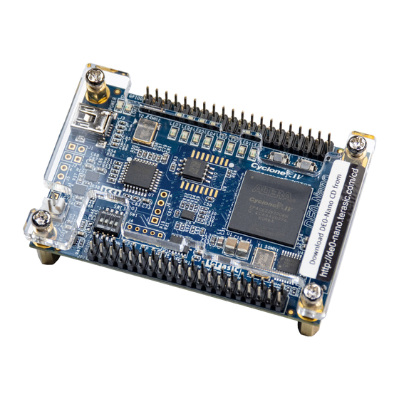
De0-Nano
Terasic De0-Nano Manuals
Manuals and User Guides for Terasic De0-Nano. We have
1
Terasic De0-Nano manual available for free PDF download: User Manual
Terasic De0-Nano User Manual (156 pages)
Brand:
Terasic
| Category:
Motherboard
| Size: 4 MB
Table of Contents
Table of Contents
2
Chapter 1 Introduction
5
Features
5
The DE0-Nano Board
5
Configuration Status and Set-Up Elements
6
Expansion Header
6
General User Input/Output
6
Memory Devices
6
About the KIT
7
DE0-Nano Kit Package Contents
7
Getting Help
7
CHAPTER 2 DE0-Nano Board Architecture
8
Layout and Components
8
The DE0-Nano Board PCB and Component Diagram
8
Block Diagram of the DE0-Nano Board
9
The DE0-Nano Board PCB and Component Diagram (Bottom View)
9
Power-Up the DE0-Nano Board
10
CHAPTER 3 Using the DE0-Nano Board
11
General User Input/Output
12
JTAG Chain
12
JTAG Chain on DE0-Nano Board
12
Pushbuttons
12
Connections between the Push-Buttons and Cyclone IV FPGA
13
Leds
13
Pushbuttons Debouncing
13
Connections between the Leds and Cyclone IV FPGA
14
DIP Switch
14
Pin Assignments for Leds
14
Pin Assignments for Push-Buttons
14
Connections between FPGA and SDRAM
15
Pin Assignments for DIP Switches
15
SDRAM Memory
15
SDRAM Pin Assignments
15
I2C Serial EEPROM
16
Connections between FPGA and EEPROM
17
Expansion Headers
17
Pin Assignments for I2C Serial EEPROM
17
GPIO-0 Pin Assignments
18
Pin Arrangement of the GPIO Expansion Headers
18
Pin1 Locations of the GPIO Expansion Headers
18
GPIO-1 Pin Assignments
19
A/D Converter and 2X13 Header
20
Pin Distribution of the 2X13 Header
21
Wiring for 2X13 Header and A/D Converter
21
Pin Assignments for 2X13 Header
22
Pin Assignments for ADC
22
Pin1 Locations of the 2X13 Header
22
Clock Circuitry
23
Digital Accelerometer
23
Pin Assignments for Digital Accelerometer
23
Wiring between the ADXL345 and the Cyclone IV E Device
23
Block Diagram of the Clock Distribution
24
Portable Battery Connection
24
Power Supply
24
DE0-Nano Power Distribution System
25
Power Distribution System
25
CHAPTER 4 DE0-Nano Control Panel
26
The DE0-Nano Control Panel
27
The DE0-Nano Control Panel Concept
27
Controlling the Leds
28
Switches and Pushbuttons
28
Memory Controller
29
Monitoring Switches and Buttons
29
Accessing the SDRAM
30
Acceleration Values Convert Rule
31
Digital Accelerometer
31
Adc
32
ADC Readings
32
Digital Accelerometer Status
32
Overall Structure of the DE0-Nano Control Panel
33
The Block Diagram of the DE0-Nano Control Panel
33
CHAPTER 5 DE0-Nano System Builder
34
General Design Flow
34
Introduction
34
The General Design Flow of Building a Design
35
Input Project Name
36
Install and Launch the DE0-Nano System Builder
36
The DE0-Nano System Builder Window
36
Using DE0-Nano System Builder
36
System Configuration
37
System Configuration Group
37
The DE0-Nano Board Type and Project Name
37
GPIO Expansion Group
38
Project Setting Management
38
Project Generation
39
Project Settings
39
The Files Generated by DE0-Nano System Builder
39
CHAPTER 6 Tutorial: Creating an FPGA Project
40
Before You Begin
41
Found New Hardware Wizard
42
The Driver Is Found in a Specific Location
42
Specify the Location of the Driver
43
Browse to Find the Location
44
There Is no Need to Test the Driver
44
Assign the Device
45
The Driver Is Installed
45
What You will Learn
45
New Project Wizard Introduction
46
Project Information
47
Specify the Device Example
48
Creating an FPGA Design
49
New BDF
50
Adding a Verilog HDL to the Schematic
51
Bank BDF
51
Saving the Verilog HDL File
52
Create Symbol File was Successful
53
The Verilog File of Simple_Counter.V
53
Adding the Symbol to the BDF
54
Placing the Simple_Counter Symbol
54
Adding a Megafunction to the Schematic
55
Mega Wizard Plug-In Manager
55
Megawizard Plug-In Manager [Page 2A] Selections
56
Place the PLL Symbol
61
PLL Symbol
61
Adding an Input Pin to the Schematic
62
Input Pin Symbol
62
Adding an Output Bus to the Schematic
63
Connecting the PLL Symbol and Input Port
63
Change the Input Port Name
64
Adding a Multiplexer to the Schematic
65
Change the Output BUS Name
65
Circuit Schematic (BDF)
65
Selecting Lpm_Mux
66
Lpm_Mux Settings
67
Lpm_Mux Symbol
68
Place the Lpm_Mux Symbol
68
Renamed Counter_Bus_Mux Bus Lines
69
Rename the Output Pin
70
Adding the KEY [0] Input Pin
71
Assign the Pins
71
Pin Information Setting
72
Pin Planner Example
72
Completed Pin Planning Example
73
Create a Default Timequest SDC File
73
Compile Your Design
74
Default SDC
74
Compilation Message for Project
75
Compilation Report Example
76
Program the FPGA Device
76
Programmer Window
77
Hardware Setting
78
Downloading Complete
79
Verify the Hardware
79
Device and Options
80
Setting Unused Pins
81
CHAPTER 7 Tutorial: Creating a Nios II Project
82
New Project Wizard
83
Add the JTAG UART Component
94
JTAG Uart’s Add Wizard
95
Jtag Uart
96
Rename JTAG UART
97
Add On-Chip Memory
98
On-Chip Memory Box
99
Update Total Memory Size
100
Rename On-Chip Memory
101
Update CPU Settings
102
Updated CPU Settings
103
Add PIO
104
Auto-Assign Base Addresses
107
No Errors or Warnings
107
Generate SOPC
108
Return to Quartus II after Exiting SOPC Builder
109
SOPC Builder Generation Successful
109
New Verilog File
110
A Blank Verilog File
111
Blank Pins
117
Download the Hardware Design
117
Set Pins
117
Hardware Setup Window
118
Quartus II Programmer
119
Create a Hello_World Example Project
120
Nios II IDE New Project Wizard
121
Nios II IDE C++ Project Perspective for Hello_World_0
122
Build and Run the Program
123
Nios II IDE Hello_World_0 Build Completed
123
Edit and Re-Run the Program
124
Hello_World_0 Program Output
124
The System.h File
126
Why the LED Blinks
126
Debugging the Application
127
Set Breakpoint
127
Configure System Library
128
Configuring System Library Properties
129
CHAPTER 8 DE0-Nano Demonstrations
130
System Requirements
130
Demonstration Batch File
131
Demonstration Setup
131
Demonstration Source Code
131
Pulse Width Modulation
131
ADC Reading
132
ADC Reading Block Diagram
132
Design Concept
132
DIP Switch Settings
133
X13 Header
134
ADC Reading Hardware Setup
135
SOPC Block Diagram
136
SOPC Demo
136
Accelerometer Control
137
PIO Controller
137
DATA_FORMAT Register
138
Register 0X30
138
Wire SPI Timing Diagram
138
4-Wire SPI Timing Diagram
139
EEPROM Control
139
EPCS Control
139
EPCS Interface Connection
139
DE0-Nano on Level Surface
142
G-Sensor
142
G-Sensor Block Diagram
142
SDRAM Test by Nios II
143
Block Diagram of the SDRAM Basic Demonstration
144
Configuring the Cyclone IV FPGA
11
Configuring the Spansion EPCS64 Device
11
Control Panel Setup
26
Design Flow
40
Creation of Hardware Design
82
Required Features
82
Breathing Leds
130
Chapter 9 Appendix
147
Convert SOF to JIC
147
Programming the Serial Configuration Device
147
Convert Programming Files Dialog Box
148
Highlight Flash Loader
149
Select Devices Page
150
Convert Programming Files Page
151
Write JIC File into Serial Configuration Device
152
Erase the Serial Configuration Device
153
Quartus II Programmer Window with One JIC File
153
Erasing Setting in Quartus II Programmer Window
154
EPCS Message
155
EPCS Programming Via Nios-2-Flash-Programmer
155
Advertisement
Advertisement
Related Products
Terasic DE0-CV
Terasic DE1-SOC
Terasic DE10-Standard
Terasic de10-nano
Terasic Altera DE3
Terasic DE1-SoC-MTL2
Terasic DE10-Lite
Terasic ALTERA DE4
Terasic Altera DE2-70
Terasic DE0-Nano-SoC
Terasic Categories
Motherboard
Microcontrollers
Computer Hardware
Robotics
Touch Panel
More Terasic Manuals
Login
Sign In
OR
Sign in with Facebook
Sign in with Google
Upload manual
Upload from disk
Upload from URL