Sign In
Upload
Manuals
Brands
Tennant Manuals
Scrubber
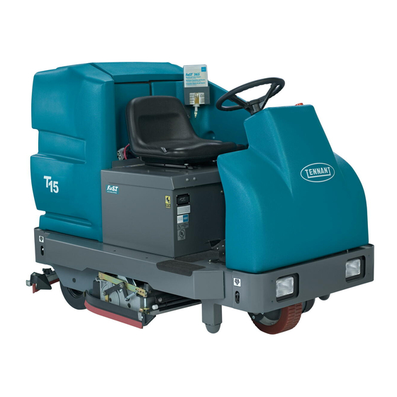
T15
Tennant T15 Manuals
Manuals and User Guides for Tennant T15. We have
3
Tennant T15 manuals available for free PDF download: Service Information Manual, Operator's Manual, Instruction Bulletin
Tennant T15 Service Information Manual (270 pages)
Floor Machine T15
Brand:
Tennant
| Category:
Scrubber
| Size: 7 MB
Table of Contents
Table of Contents
3
Safety Precautions
6
General Machine Information
7
Touch Panel Detail
9
Switches & Circuit Breakers
10
Component Locator
17
Specifications
18
Dimensions & Capacities
18
Performance
18
Power Type
19
Tires
19
Fast System
19
Dimensional Drawings
20
Basic Troubleshooting
22
Maintenance & Repair
23
Maintenance Checkpoints
24
Maintenance Chart
25
Lubrication
26
Steering Caster Pivot Bearing
26
Rear Squeegee Casters
26
Steering Gear Chain
26
Batteries
27
Charging Batteries
28
To Replace Batteries
31
To Access Control Panel
33
Control Panel
34
Instrument Panel
35
To Replace Touch Panel
35
To Replace Circuit Board
40
Circuit Breakers
43
Resetable Circuit Breakers
43
To Replace Circuit Breaker
44
Fuses
47
To Replace Fuse
47
Directional Control Pedal
49
To Replace Propel Motor Controller
50
To Replace Taillight Bulb
52
Scrub Head
53
Scrub Head Links
53
To Replace Scrub Head Links
54
To Remove Disc Scrub Head
55
To Install Disc Scrub Head
57
To Replace Disc Scrub Head Brush Motor
59
To Remove Cylindrical Scrub Head
63
To Install Cylindrical Scrub Head
65
To Replace Cylindrical Scrub Head Brush Motor
67
To Replace Brush Drive Belt
72
Cylindrical Brush Drive Belt
75
Scrub Head Floor Skirts
76
To Adjust Disc Scrub Head Skirts
76
Disc Scrub Head Skirts
77
To Replace Disc Scrub Head Skirts
77
Cylindrical Brush Head Debris Tray
78
To Remove Debris Tray
78
To Install Debris Tray
80
To Replace Debris Tray Skirt
81
Scrub Brushes
82
Disc Scrub Brushes
82
To Replace Disc Scrub Brushes
82
Cylindrical Scrub Brushes
84
To Replace Cylindrical Scrub Brushes
84
To Check and Adjust Cylindrical Brush Pattern
86
To Replace Scrub Head Lift Actuator
90
Home Find
90
Scrub Head Lift Actuator
93
MAINTENANCE & REPAIR (Continued)
94
Solution System
94
Recovery Tank
94
To Remove Recovery Tank
95
To Install Recovery Tank
99
Solution Tank
102
To Remove Solution Tank
103
To Install Solution Tank
107
To Replace Solution Valve
111
Manual Solution Valve
113
To Replace Solution Solenoid Valve
114
Solution Solenoid Valve
116
Fast System
117
Fast Supply Hose Connector
117
Fast Solution Filter Screen
117
To Replace es Pump
118
ES Pump
120
Squeegees
121
To Remove Rear Squeegee Assembly
121
To Install Rear Squeegee Assembly
123
To Level Rear Squeegee
124
To Adjust Rear Squeegee Blade Deflection
126
Rear Squeegee Casters
128
To Adjust Rear Squeegee Guide Roller
128
To Replace or Rotate Rear Squeegee (Rear) Blade
129
To Replace or Rotate Rear Squeegee (Front) Blade
131
Rear Squeegee Wheel Cams
134
Rear Squeegee Leveling Knob
134
To Replace Rear Squeegee Lift Cable
135
Side Squeegee Blades
138
Rear Squeegee Blades
139
To Replace Side Squeegee Blades
139
To Replace Rear Squeegee Lift Actuator
141
Squeegee Lift Actuator
143
To Remove Vacuum Fan Assembly
144
To Install Vacuum Fan Assembly
146
To Replace Vacuum Fan
148
Vacuum Fan
149
Pre-Sweep Brushes
150
Pre-Sweep Disk Brushes
150
Replacing the Disk Brushes
150
Pre-Sweep Cylindrical Brush
152
Checking and Adjusting Cylindrical Brush Pattern
152
Replacing the Pre-Sweep Cylindrical Brush
154
Pre-Sweep Skirts and Seals
156
Pre-Sweep Side Skirts
156
Pre-Sweep Recirculation Skirt
156
Pre-Sweep Rear Skirt
156
Pre-Sweep Brush Drive Belt
157
Static Drag Strap
158
Tires
158
Rear Tires and Wheels
159
To Remove Rear Tire
159
To Install Rear Tire
160
To Replace Rear Wheel Bearings
161
Front Tire and Wheel
163
Front Wheel Support Caster Bearing Assembly
163
To Remove Front Drive Assembly
163
To Install Front Drive Assembly
165
Propel Motor Service
166
General Information
166
Terminal Connections
167
Electric Brake Disassembly
168
Brake Disk Replacement
172
Tire Replacement
173
Commutator Brush Replacement
177
To Replace Drive Assembly Caster Bearing and Thrust Washers
180
To Replace Drive Assembly Pivot Cone Bearing
183
Steering
185
To Adjust Steering Chain
185
To Replace Steering Chain
186
To Replace Large Steering Sprocket
187
To Replace Small Steering Sprocket
188
To Replace Steering Housing Bearings
190
To Replace Steering U-Joint
194
Seat
196
Operator Seat
196
To Remove Seat Assembly
196
To Install Seat Assembly
198
To Adjust Seat Position
199
Pushing,Towing,And Transporting the Machine
200
Pushing or Towing the Machine
200
Transporting the Machine
200
Machine Jacking
202
Storage Information
203
Freeze Protection
203
MAINTENANCE & REPAIR (Continued)
185
Electrical
205
Electrical Schematics
208
Harness Drawings
216
Electrical Symbols & Terms
217
Key Switch
218
Key off Power Distribution
219
Key START Power Distribution
220
Key on Power Distribution
221
Power up Troubleshooting
222
Touch Panel Wiring
223
Touch Panel Troubleshooting
224
Scrub Brushes on
225
Vacuum Fan(S) on & Squeegee down
226
Vacuum Fan(S) off & Squeegee up
227
Vacuum Fan Troubleshooting
228
Squeegee Troubleshooting
230
Scrub Head down & Conventional Solution Valve on
232
Scrub Head up
233
Forward Propel
234
Reverse Propel
235
Neutral (no Propel) with Brake Pedal Depressed
236
Diagnostics and Troubleshooting
237
Propel Controller
239
Operating Lights
240
Horn on
240
Extended Scrub (ES) System on
241
Power Wand on
241
ES System Troubleshooting
243
ES Filter Flush Troubleshooting
244
Pre-Sweep System on
245
Pre-Sweep Dust Control on
246
Fast System on
247
Fault Indications
249
Battery Charger Troubleshooting
252
Machine Control Board Connectors
253
Propel Controller Connectors
254
Normal Mode
256
Self-Test Mode
258
Error Codes
259
Squeegee/Scrub Button Pressed
259
Troubleshooting
260
Manual Mode
262
Enable/Disable Chart
263
Input Display Mode
264
Restricted down Pressure Mode
265
Operating & Configuration Modes
266
Software Revision Date Display Mode
266
T15 331555
266
Home Find
270
Advertisement
Tennant T15 Operator's Manual (114 pages)
(Electric) Rider Scrubber
Brand:
Tennant
| Category:
Scrubber
| Size: 2 MB
Table of Contents
Table of Contents
3
Safety Precautions
5
Machine Components
7
Control Panel Symbols
8
Controls and Instruments
9
Operation of Controls
10
Directional Pedal
10
Brake Pedal
11
Parking Brake
11
Key Switch
12
Power Kill Switch
12
Operating Lights Switch
12
Hourmeter
12
Operator Seat
13
Seat Support Arm
13
Solution Flow Lever
13
Scrubbing Switch
14
Squeegee Switch
15
ES Switch (Option)
15
Fast Switch (Option)
15
Ec--H2O Switch (Option)
16
Recovery Tank Full Indicator
16
Battery Discharge Indicator
17
Pre--Sweep Switch (Option)
18
Dust Control Switch (Option)
18
Side Brush Pedals (Option)
18
Circuit Breakers
19
Fuse
20
Steering Wheel
20
Squeegee Wheel Cams
21
Squeegee Leveling Knob
21
Side Squeegee down Pressure Controls
21
How the Machine Works
22
Brush and Pad Information
22
Home Find... Go to
23
Fast Scrubbing System
24
Ec--H20 System (Option)
25
Pre-Operation Checklist
26
Installing Fast PAK Agent
27
Starting the Machine
28
Filling the Tanks
29
Home Find... Go to
30
Scrubbing
31
Home Find... Go to
32
Home Find... Go to
33
Home Find... Go to
34
Double Scrubbing
35
Stop Scrubbing
36
Home Find... Go to
37
Draining and Cleaning the Tanks
38
Home Find... Go to
39
Home Find... Go to
40
Home Find... Go to
41
Stop the Machine
42
Options
43
Side Brush
43
Pre--Sweep Assembly
44
Debris Hopper
45
To Empty the Pre--Sweep
45
Home Find... Go to
46
Assembly
47
To Remove the Pre--Sweep Assembly
47
To Mount the Pre--Sweep Assembly
48
Home Find... Go to
49
Power Wand
50
Home Find... Go to
51
Home Find... Go to
52
Home Find... Go to
53
Vacuum Wand
54
Home Find... Go to
55
Home Find... Go to
56
Positive Drain Control Valve
57
Rollout Battery
58
Machine Troubleshooting
63
Maintenance
65
Maintenance Chart
65
Lubrication
67
Steering Caster Pivot Bearing
67
Rear Squeegee Casters
67
Steering Gear Chain
67
Batteries
68
Charging the Batteries
69
Self--Diagnostic Test
72
Electric Motors
74
Pre--Sweep Brushes
74
Pre--Sweep Disk Brushes
74
Replacing the Disk Brushes
74
Pre--Sweep Cylindrical Brush
76
Checking and Adjusting Cylindrical Brush Pattern
76
Replacing the Pre--Sweep
78
Replacing the Pre--Sweep Cylindrical Brush
78
Scrub Brushes
80
Disk Scrub Brushes
80
Replacing the Disk Scrub Brushes
80
Cylindrical Scrub Brushes
83
Checking and Adjusting Cylindrical Scrub Brush Pattern
83
Replacing the Cylindrical Scrub Brushes
86
Solution System
88
Recovery Tank
88
Solution Tank
89
Fast System
89
Fast Supply Hose Connector
89
Fast / Solution Filter Screen
90
Fast System Air Pump Filter (S/N 000000--015437)
90
Fast System Injector Filters (S/N 015438-- )
90
Ec--H2O Module Flush Procedure
91
Rear Squeegee Assembly
92
Removing the Rear Squeegee Assembly
92
Replacing the Rear Squeegee Assembly
93
Leveling the Rear Squeegee
93
Adjusting Rear Squeegee Blade Deflection
94
Adjusting the Squeegee Guide Roller
95
Rear Squeegee Blades
95
Replacing or Rotating the Rear Squeegee Blade
95
Replacing or Rotating the Front Squeegee Blade
97
Side Squeegee Blades
98
Replacing Side Squeegee Blades
98
Skirts and Seals
99
Pre--Sweep Side Skirts (Option)
99
Pre--Sweep Recirculation Skirt (Option)
99
Pre--Sweep Rear Skirt (Option)
99
Belts and Chains
100
Scrub Brush Drive Belts
100
Pre--Sweep Brush Motor Belt (Option)
100
Pre--Sweep Brush Drive Belt (Option)
100
Static Drag Strap
101
Steering Gear Chain
101
Tires
101
Pushing, Towing, and Transporting the Machine
102
Pushing or Towing the Machine
102
Transporting the Machine
102
Machine Jacking
104
Storage Information
105
Freeze Protection
105
Ec--H2O Model
106
Flushing Antifreeze from
106
The Ec--H2O Module
106
Specifications
107
General Machine Dimensions/Capacities
107
General Machine Performance
107
Power Type
108
Tires
108
Fast System
108
Ec--H2O System (Option)
108
Machine Dimensions
109
Index
110
Tennant T15 Instruction Bulletin (9 pages)
Brand:
Tennant
| Category:
Scrubber
| Size: 0 MB
Table of Contents
Installation Instructions for Kit Number 223282
1
Synopsis
1
Special Tools / Considerations
1
Preparation
1
Installation
1
Electrical Panel
3
FIG. 1- Switch and Circuit Breaker
3
FIG. 2- Hose Bag Mounting Hole Dimensions
3
Tank Cover
4
FIG. 3- Power Wand Mounting Assembly
4
FIG. 4- Pump, Hoses, and Fittings
5
FIG. 5- Power Wand Hose Assembly
5
FIG. 6- Power Wand Assembly
6
FIG. 7- Electrical Schematic
7
Bill of Materials for Kit , CI, Wand, Power [7200]-223282
8
Advertisement
Advertisement
Related Products
Tennant T12
Tennant T16
Tennant T12XP
Tennant T1 Li
Tennant T191
Tennant T1581
Tennant t500e
Tennant T600e
Tennant T981
Tennant T391
Tennant Categories
Scrubber
Floor Machine
Vacuum Cleaner
Blower
Cleaning Equipment
More Tennant Manuals
Login
Sign In
OR
Sign in with Facebook
Sign in with Google
Upload manual
Upload from disk
Upload from URL