Sign In
Upload
Manuals
Brands
Teledyne Manuals
Measuring Instruments
ULTRAFLOW 150
Teledyne ULTRAFLOW 150 Manuals
Manuals and User Guides for Teledyne ULTRAFLOW 150. We have
1
Teledyne ULTRAFLOW 150 manual available for free PDF download: Operation Manual
Teledyne ULTRAFLOW 150 Operation Manual (162 pages)
GAS FLOW AND TEMPERATURE MONITOR
Brand:
Teledyne
| Category:
Measuring Instruments
| Size: 5 MB
Table of Contents
Table of Contents
4
1 Safety
8
Internationally Recognized Symbols Used on Teledyne Monitor Labs Equipment
8
2 System Overview
10
System Description, Standard Equipment
10
Transducer Interface Enclosure (TIE)
10
Purge Nozzle Assemblies
10
Protective Purge System
12
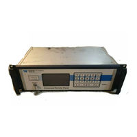
Enhanced Remote Panel
12
3 Optional Equipment
14
Protective Purge Air System, (Dual)
14
Local User Interface Key Pad and Display
14
Dual Analog Input Board
15
Barometric Pressure Sensor Assembly
15
External Temperature Measurement
16
Link Rod
17
6PT I/O PC Board Option for 150DI
18
4 Theory of Operation
19
Physics of Measurement
19
Time of Flight Theory
19
Flow Volume Measurement
21
Wet Basis and Dry Basis Measurements
21
Correction to Standard Temperature and Pressure
21
Monitor Specific Theory
22
Box Car Integration
22
Operational Modes of the Transducer Interface Enclosure
22
5 Transducer Interface Enclosure (Tie)
25
Mechanical Description
25
Electrical Description
26
External Interface PC Board
26
Power Supply Board
26
Flow Mother Board
26
Preamp Boards
32
Optional) Dual Analog Input Board
33
Optional) Local User Interface Key Pad and Display Assembly
33
Individual Button Function (When Pressed by Themselves)
35
Combinations of Buttons
36
6 Enhanced Remote Panel W / Multi I/O Module
37
Overview
37
Mechanical Description
37
Electrical Description
38
Input Power Requirement
38
Circuit Description (Overview)
38
OPERATIONAL DESCRIPTION-Menu Structure and User Interface
45
Memory Test
45
Main Display Screen
46
Main Menu Screen
47
Service Data Menu
48
Status Code Help
49
Output Cal Tests
49
Output Module Configuration Menu
52
Display Properties Menu
55
Software Versions
55
System Properties Menu
55
View Trending Data
60
View Numerical Data
60
View Status History
60
View Alarms History
61
Multi I/O Software
61
Analog Outputs
61
Digital Inputs
62
Digital Outputs
62
7 Installation
69
Pre-Installation Planning and Preparation
69
Site Selection
70
Representative Sampling Location
70
Access to Sampling Location
70
Environmental Conditions at the Sampling Location
70
Equipment Mounting Considerations
71
Flange and Mounting Tube Installation
71
Purge System, Reference PURGE ASS'Y MTG., PLUMBING & CLEARANCE REQUIREMENTS Drawing
72
Purge Nozzle and Mounting Flange Assembly, Reference PURGE NOZZLE and MTG. PLATE INSTALLATION-150 Drawing
72
Transducer Interface Enclosure Assembly, Reference XDUCER INTERFACE ENCLOSURE INSTALLATION Drawing
73
Junction Box, Reference JUNCTION BOX MTG. METHODS and CLEARANCES Drawing
73
Enhanced Remote Panel Assembly, Reference ENHANCED REMOTE PANEL ASSEMBLY Drawing
74
8 System Calibration and Adjustment
77
Transducer Interface Enclosure Calibration
77
Transducer Interface Enclosure Program Variables
77
Transducer Interface Enclosure Electronics Adjustment
84
Flow Mother Board
84
Preamp Board Adjustment
84
Remote Panel Calibration
84
Remote Program Variables
84
Enhanced Remote Panel Analog Adjustments
84
9 Maintenance
87
Maintenance Schedule
87
After Initial Installation
87
Normal Maintenance
87
Troubleshooting Guide
88
Advertisement
Advertisement
Related Products
Teledyne 1220
Teledyne 100E
Teledyne 15-0800-074
Teledyne LabMaster 10 Zi Series
Teledyne 12M
Teledyne Linea 16K CL
Teledyne SyriXus 1000x
Teledyne 11002-0201
Teledyne CombiFlash NextGen 100
Teledyne Forge 1GigE SWIR Series
Teledyne Categories
Measuring Instruments
Analytical Instruments
Test Equipment
Digital Camera
Laboratory Equipment
More Teledyne Manuals
Login
Sign In
OR
Sign in with Facebook
Sign in with Google
Upload manual
Upload from disk
Upload from URL