Sign In
Upload
Manuals
Brands
Teledyne Tekmar Manuals
Laboratory Equipment
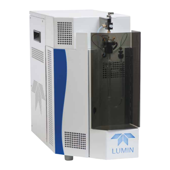
Lumin 15-2500-074
Teledyne Tekmar Lumin 15-2500-074 Manuals
Manuals and User Guides for Teledyne Tekmar Lumin 15-2500-074. We have
1
Teledyne Tekmar Lumin 15-2500-074 manual available for free PDF download: User Manual
Teledyne Tekmar Lumin 15-2500-074 User Manual (224 pages)
Brand:
Teledyne Tekmar
| Category:
Laboratory Equipment
| Size: 21 MB
Table of Contents
Table of Contents
3
Essential Instructions
11
Preface
11
Teledyne Tekmar Customer Support Center
11
Warranty
11
Notations and Hazard Severity Levels
12
Lumin Safety Symbols
13
Lumin Safety Labels
15
Working Safely
16
Chapter 1: Introduction
19
Purge and Trap Background
19
Purge and Trap Fundamentals
19
Brief History
20
Purge and Trap Operation Overview
20
Trapping, Adsorption and Desorption
21
Lumin Specifications
22
Lumin Component Overview
25
CPU Communication Board Location
25
Sample Mount and Sparger
26
Guardian™ Foam Sensor & Eliminator (Optional)
26
Status Light
27
Sample Purge Gas Inlet
27
Unit Status Light/Mode Indicator
27
Mass Flow Controller (MFC)
28
Sample Pathway
28
Mass Flow Controller
28
Analytical Trap
29
Moisture Control System (MCS)
29
Lumin Analytical Trap Compartment
29
Carrier Gas Inlet Line/Heated Sample Transfer Line
30
Moisture Control System
30
Carrier Gas Inlet Line and Heated Sample Transfer Line
30
Valving
31
Heated 6-Port Valve
31
3-Port Sample Valve
32
24VDC Power Supply
33
5VDC Power Supply
33
Multi-Channel Temperature Control Board
34
CPU Communication Board (Master Board)
35
DC Valve Control Board
36
Optional Autosampler
37
Optional Guardian™ Foam Sensor and Foam Eliminator
37
Chapter 2: Installation and Setup
39
Pre-Installation
39
Overview
39
Operating Environment
39
Work Surface Requirements
39
Electrical Requirements
40
Gas Supply Requirements
40
Minimum Computer Requirements
42
Required Tools and Supplies for Installation
42
Unpacking the Lumin
43
Installation Kit Box
43
Concentrator Overview
44
Electrical and Data Connections
47
AC Power Cord
47
Lumin Power Entry Module
47
Connect the USB Interface Cable
48
GC I/O (Input/Output) Connection
48
Lumin USB Connection
48
Connecting the Lumin Sample Purge Gas Supply
49
Lumin Carrier Gas and Sample Transfer Line Connection to the Gas Chromatograph (GC)
50
Rear of Lumin - Sample Purge Gas Connection
50
Routing the Drain Tubing
52
Install Lumin Teklink Software
53
Lumin Teklink Installation Wizard
53
Microsoft ® SQL Server Installation
54
Net Installation
55
USB Driver Installation
55
Create an Instrument Profile
56
Options Tab
56
Leak Check Tab
58
Autosampler Setup and Connection
60
Communication Cable Connection
60
Aqueous Transfer Line Installation
60
Autosampler Method Configuration
61
Guardian™ Foam Sensor and Foam Eliminator (Optional)
61
Aqueous Transfer Line Access Point
61
Configuring the Guardian™ Foam Sensor & Eliminator
63
Configuration Dialog- Guardian™ Foam Sensor
63
Chapter 3: Lumin Teklink Software Overview
65
About Lumin Teklink Software
65
The Lumin Teklink Software Environment
65
Touchscreen Capability
65
Pinnable" Screens
66
Title Bar
66
On-Screen Keyboard
66
Pin Function
66
Open, Save, Load, and Print Buttons
67
Instrument Control Buttons
68
Delete at Next Archive Check-Box
68
Control Buttons
68
Primary Screens
69
The Home Screen
69
Open Dialog Source Drop-Down Menu
69
Home Screen
69
Instrument Status Panel
70
Methods Screen
71
Standby Tab
71
Instrument Status Zone Display Options
71
Purge Tab
72
Desorb Tab
74
Bake Tab
75
Aquatek 100 Tab
76
Schedules Screen
78
Tools Screen
79
Prime Menu
80
Commands Menu
80
System Menu
82
Tools - Configuration - General Tab
83
Tools - Configuration - Leak Check Tab
85
Tools - Instrument Manager
86
System Properties Dialog
86
About
92
Diagnostics
92
About Dialog
92
Diagnostics - Valves and Flows
93
Create an Instrument Profile
96
Connect to an Instrument Profile
99
Deactivate an Instrument Profile
100
Creating a Method
101
Save the Method
102
Open a Method
103
Print a Method
105
Save Schedule
109
Load (Run) the Schedule
110
Abort a Sample or Schedule
111
Chapter 4: Instrument Operations
115
Concentrator Mode Descriptions
115
Lumin Valve Output Chart
117
Lumin with Aquatek 100 Valve Output Chart
120
Optimization
124
Temperatures
124
Standby Mode
124
Purge Ready Mode
125
Pre-Purge Mode
125
Sample Temperature and Pre-Heat Mode
125
Purge Mode
126
Dry Purge Mode
126
Desorb Ready Mode
126
Desorb Pre-Heat Mode
126
Desorb Mode
127
Bake Mode
127
Analytical Trap Recommended Conditioning Settings
127
Analytical Trap Recommended Operating Conditions
128
Chapter 5: Maintenance and Troubleshooting
129
Replacing Parts
129
Preventative Maintenance Checks
130
Daily Maintenance Checks
130
Weekly Maintenance Checks
130
Monthly Maintenance Checks
130
Preventative Maintenance Chart
131
GC/IO Cable and GC Type Reference
132
Instrument Access Panels
133
Plumbing Overview
136
Electrical Overview
138
Power Supplies
138
Printed Circuit Boards
139
Glassware Cleaning Procedures
140
Sparger Replacement
141
Analytical Trap Replacement
143
Analytical Trap Conditioning
146
Analytical Trap Heater Jacket
147
Analytical Trap Cooling Fan
149
MCS Cooling Fan
153
Pencil Filter Replacement
156
Check Valve
157
Valve Manifold Replacement
158
Valve Replacement
159
Moisture Control System (MCS)
161
Mass Flow Controller (MFC)
163
Mass Flow Controller
163
6-Port Valve
164
Power Entry Module (PEM) Fuse Replacement
165
Fuse Module Removed
167
Multi-Channel Temperature Control Board Fuse Replacement
168
Main Fuse
168
Multi-Channel Temperature Control Board
168
Heater Output Fuses
170
Multi-Channel Temperature Control PCB Replacement
172
CPU Communication (Master) PCB Replacement
175
CPU Communication Board (Master Board)
175
DC Valve Control PCB Replacement
178
5VDC Power Supply Replacement
181
5VDC Power Supply
181
24VDC Power Supply Replacement
183
24VDC Power Supply
183
Upgrade Firmware
184
Download Firmware
184
Upgrade Board Firmware
184
Upgrade Software
184
Troubleshooting
185
Benchmark Test
185
Benchmark Test Prompt
186
Initial Leak Check
187
Instrument Status During Leak Check
187
Advanced Leak Check Guidelines
189
Advanced Leak Checking Flow Chart
192
Leak Checking Flow Chart
192
No Power Flow Chart
193
Top-Of-Trap (TOT) Injection Port
194
4-Waytee
194
No Response Flow Chart
198
Low Response Flow Chart
199
Carryover Contamination Flow Chart
200
Returning the Lumin
200
Unit and Parts Disposal
201
Technical Assistance
201
Teledyne Tekmar Customer Support
201
Appendix A: Diagrams
203
Lumin Electrical Schematic
204
Lumin Plumbing Diagram
205
Lumin Flow Diagrams
206
Lumin - Basic Flow Diagram
206
Lumin - Standby Dry Purge Flow Diagram
207
Lumin - Standby/Dry Purge Flow Diagram
207
Lumin Purge Flow Diagram
208
Lumin - Purge Flow Diagram
208
Lumin Desorb Flow Diagram
209
Lumin - Desorb Flow Diagram
209
Lumin Bake Flow Diagram
210
Lumin - Bake Flow Diagram
210
Lumin with Guardian™ Foam Sensor (GFS) & Eliminator Flow Diagramsa-9
211
Lumin with GFS & Eliminator - Basic Flow Diagram
211
Lumin with GFS & Eliminator - Standby/Dry Purge Flow Diagram
212
Lumin with GFS & Eliminator - Eliminator Ready Flow Diagram
213
Lumin with GFS & Eliminator - Purge Flow Diagram
214
Lumin with GFS & Eliminator - Add Defoamer Flow Diagram
215
Lumin with GFS & Eliminator - Eliminator Rinse Flow Diagram
216
Lumin with GFS & Eliminator - Desorb Flow Diagram
217
Lumin with GFS & Eliminator - Bake Flow Diagram
218
Advertisement
Advertisement
Related Products
Teledyne Tekmar 15-3200-074
Teledyne Tekmar Atomx XYZ
Teledyne Tekmar Torch
Teledyne Tekmar Categories
Laboratory Equipment
More Teledyne Tekmar Manuals
Login
Sign In
OR
Sign in with Facebook
Sign in with Google
Upload manual
Upload from disk
Upload from URL