Sign In
Upload
Manuals
Brands
TELEDYNE API Manuals
Analytical Instruments
T802
User Manuals: TELEDYNE API T802 Oxygen Analyzer
Manuals and User Guides for TELEDYNE API T802 Oxygen Analyzer. We have
1
TELEDYNE API T802 Oxygen Analyzer manual available for free PDF download: User Manual
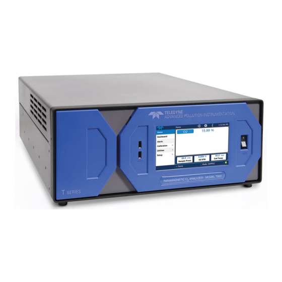
TELEDYNE API T802 User Manual (128 pages)
Paramagnetic Oxygen Analyzer with NumaView software
Brand:
TELEDYNE API
| Category:
Analytical Instruments
| Size: 9 MB
Table of Contents
Warranty
6
Table of Contents
8
List of Figures
12
1 Introduction, Specifications, Approvals, & Compliance
14
Specifications
14
Table 1-1. Specifications
14
Safety
15
Emc
15
Other Certifications
15
2 Getting Started
16
Unpacking
16
Ventilation Clearance
17
Table 2-1. Ventilation Clearance
17
Instrument Layout
18
Figure 2-1. Front Panel Layout
18
Front Panel
18
Figure 2-2. Rear Panel Layout, Base Unit (Options Include Additional Pneumatic Ports)
19
Rear Panel
19
Table 2-2. Rear Panel Description
20
Figure 2-3. Internal Chassis Layout
21
Internal Chassis
21
Connections and Startup
22
Connecting Power
22
Electrical Connections
22
Connecting Analog Outputs
23
Figure 2-4. Analog Output Connector
23
Table 2-3. Analog Output Pin Assignments
23
Current Loop Analog Outputs (Option 41) Setup
24
Figure 2-5. Current Loop Option Installed on the Motherboard
24
Connecting the Status Outputs (Digital Outputs)
25
Figure 2-6. Status Output Connector for Digital Outputs
25
Connecting the Control Inputs (Digital Inputs)
26
Figure 2-7. Energizing the Control Inputs
26
Table 2-4. Status Output Pin Assignments
26
Concentration Alarm Relay (Option 61)
27
Connecting Communications Interfaces
27
Figure 2-8. Concentration Alarm Relay
27
Table 2-5. Control Input Pin Assignments
27
Figure 2-9. Rear Panel Connector Pin-Outs for RS-232 Mode
28
Figure 2-10. Default Pin Assignments for CPU COM Port Connector (RS-232)
29
Figure 2-11. Jumper and Cables for Multidrop Mode
31
Figure 2-12. RS-232 Multidrop PCA Option Host/Analyzer Interconnect Diagram
32
Pneumatic Connections
33
Basic Pneumatic Connections
34
Critical Tubing, Pressure, Venting and Exhaust Requirements
34
Figure 2-13. Basic Configuration, Using Bottled Span Gas
34
Figure 2-14. Internal Gas Flow, Basic Configuration
36
Figure 2-15. Internal Gas Flow with CO
36
Pneumatic Flow Diagrams
36
Figure 2-16. Status Screens at Startup
37
Startup
37
Startup, Functional Checks and Calibration
37
Alerts: Warnings and Other Messages
38
Figure 2-32. Home Page Example (When Installed, CO2 Option Conc Displays below O2 Conc)
38
Figure 2-33. Viewing Active Alerts Page
38
Calibration
39
Figure 2-34. Sample Dashboard Page
39
Functional Checks
39
Menu Overview
40
Table 2-9. Menu Overview
40
Figure 2-35. User Interface Orientation
41
Home Page
41
Figure 2-36. Concentration and Stability Graph (Top) and Sample Flow Graph (Bottom)
42
Dashboard
43
Figure 2-37. Dashboard Page
43
Alerts
44
Figure 2-38. Navigating to the Active Alerts Page
44
Calibration
45
Figure 2-39. Active Alerts Cleared
45
Figure 2-40. Utilities>Alerts Log of Active and Past Alerts and Events
45
Setup
46
Table 2-10. Utilities Submenu Descriptions
46
Utilities
46
Setup Menu: Features/Functions Configuration
47
Setup>Data Logging (Data Acquisition System, DAS)
47
Figure 2-41. Datalog Configuration, New Log Page
47
Figure 2-42. Datalog Configuration, Existing Log
47
Figure 2-43. Creating a New Data Log
48
Configuring Trigger Types: Periodic
49
Figure 2-44. Datalog Periodic Trigger Configuration
49
Configuring Trigger Types: Conditional
50
Downloading das (Data Acquisition System) Data
50
Figure 2-45. Datalog - Conditional Trigger Configuration
50
Figure 2-46. das Download Page
50
Figure 2-47. Events List
51
Figure 2-48. Event Configuration
51
Setup>Events
51
Editing or Deleting Events
52
Figure 2-49. Configured Event Sample
52
Figure 2-50. Edit or Delete an Event
52
Figure 2-51. Dashboard Display and Configuration
53
Setup>Dashboard
53
Using Events as Triggers for Data Logging
53
Setup>Vars
54
Table 2-11. Typical Variables with Descriptions
54
Figure 2-52. Homescreen Configuration
55
Setup>Homescreen
55
Figure 2-53. Digital Outputs Setup
56
Setup>Digital Outputs
56
Figure 2-54. Analog Output Configuration Example
57
Setup>Analog Outputs
57
Figure 2-55. Analog Outputs Group Calibration Screen
58
Figure 2-56. Analog Outputs Manual Calibration Screen (AOUT2 Example)
58
Table 2-12. Analog Output Voltage/Current Range
58
Figure 2-57. Setup for Checking / Calibrating DCV Analog Output Signal Levels
59
Manual Calibration of Voltage Range Analog Outputs
59
Table 2-13. Voltage Tolerances
59
Figure 2-58. Setup for Checking / Calibration Current Output Signal Levels
60
Manual Adjustment of Current Range Analog Outputs
60
Figure 2-59. Alternative Setup Using 250Ω Resistor for Checking Current Output Signal Levels
61
Setup>Instrument
61
Table 2-14. Current Loop Output Check
61
Table 2-15. Setup>Instrument Menu
61
Com1/Com2
62
Setup>Comm (Communications)
62
Table 2-16. COM1/COM2 Configuration
62
Figure 2-60. Communications Configuration, Network Settings
63
Network Settings
63
TCP Port1
63
TCP Port2
63
TCP Port3
63
Transferring Configuration to Other Instruments
64
Figure 2-61. Configuration Transfer
64
Table 2-17. Lan/Ethernet Configuration Properties
64
3 Communications and Remote Operation
66
Data Terminal/Communication Equipment (DTE DCE)
66
Modes, Baud Rate and Serial Communication
66
Serial Communication: RS-232
67
Serial Communication: RS-485 (Option)
67
Ethernet
67
Table 3-1. Ethernet Status Indicators
67
Communications Protocols
68
3.4.1 Modbus
68
Figure 3-1. MODBUS Via Ethernet
68
MODBUS Com Port Configuration
68
Figure 3-2. MODBUS Via Serial Communication (Example)
69
Figure 3-3. Serial Communication, Setting Hessen Protocol
70
Hessen
70
Hessen Com Port Configuration
70
Hessen Settings Configuration
71
Table 3-2. Teledyne Api's Hessen Protocol Response Modes
71
Table 3-3. T100, T100U Hessen Status Flags and Default Bit Assignments
72
Figure 3-4. Hessen Gas List Configuration
73
Hessen Gas List Configuration
73
Table 3-5. Hessen Gas List Definitions
73
4 Calibration
74
Important Precalibration Information
74
Calibration Requirements
74
Zero Air
74
Calibration (Span) Gas
74
Physical Range Measurements
75
Interferents
75
Data Recording Devices
75
Calibration Procedures
76
Zero Calibration Check and Actual Calibration
76
Figure 4-2. Calibration Menu for O and CO Sensors
76
Span Calibration Check and Actual Calibration
77
Calibration Quality Analysis
77
Figure 4-3. Sample Calibration Page for O Sensor
77
Table 4-4. Calibration Data Quality Evaluation
78
5 Maintenance and Service
79
Maintenance Schedule
79
Predictive Diagnostics
80
Table 5-1. Maintenance Schedule
80
Operational Health Checks
81
Software/Firmware Updates
81
Figure 5-1. Report Generation Page
81
Table 5-2. Predictive Uses for Dashboard Functions
81
Figure 5-2. Remote Update Page
82
Figure 5-3. Manual Update Page (and Other Utilities)
82
Manual Reload/Update Procedures
82
Remote Updates
82
Time Zone Changes
84
Maintenance and Service
85
Replacing the Sample Particulate Filter
85
Replacing the Sample Pump Diaphragm
86
Checking for Pneumatic Leaks
86
Simple Vacuum Leak and Pump Check
86
Vacuum Leak Check and Pump Check
86
Detailed Pressure Leak Check
87
Performing Flow Checks/Calibrations
88
Flow Check
88
Flow Calibration
88
Performing Pressure Calibration
89
Fault Diagnosis with Alerts
89
Table 5-3. Warning Alerts, Fault Conditions and Possible Causes
90
Fault Diagnosis with Dashboard Functions
91
Using the Diagnostic Signal I/O Functions
91
Table 5-4. Dashboard Functions - Possible Causes for Out-Of-Range Values
91
Using the Internal Electronic Status Leds
92
CPU Status Indicator
92
Relay PCA Watchdog and Status Leds
92
Flow Problems
93
Table 5-5. Relay PCA Watchdog and Status LED Failure Indications
93
5.6.10.1 Sample Flow Is Zero or Low
94
5.6.10.2 High Flow
95
Sample Flow Is Zero or Low but Analyzer Reports Correct Flow
95
Calibration Problems
96
5.6.11.1 Miscalibrated
96
5.6.11.2 Non-Repeatable Zero and Span
96
5.6.11.3 Inability to Span - no Span Button
96
5.6.11.4 Inability to Zero - no Zero Button
97
Other Performance Problems
97
5.6.12.1 Excessive Noise
97
5.6.12.2 Slow Response
97
Subsystem Check for Troubleshooting
98
5.6.13.1 Ac Main Power
98
5.6.13.2 DC Power Supply
99
I 2 C Bus
99
Table 5-7. DC Power Test Point and Wiring Color Code
99
Table 5-8. DC Power Supply Acceptable Levels
99
5.6.13.4 Touchscreen Interface
100
5.6.13.5 Lcd/Display Module
100
5.6.13.6 Relay Pca
100
5.6.13.7 A/D Functions
101
5.6.13.8 Status Outputs
101
5.6.13.10 Cpu
102
5.6.13.9 Pneumatic Pressure / Flow Sensor Assembly
102
5.6.13.11 Rs-232 Communications
103
5.6.13.13 Temperature Problemss
104
Optional CO Sensor
104
Service Procedures
104
5.6.14.1 Repairing Sample Flow Control Assembly
105
5.6.14.2 Disk-On-Module Replacement Procedure
106
5.6.14.3 Sensor Module Repair and Cleaning
106
Frequently Asked Questions
107
Technical Assistance
108
6 Principles of Operation
109
Oxygen (O ) Sensor Principles of Operation
109
Magnetic Properties of O Gas
109
Principle of Measurement
109
NDIR Measurement of CO2
110
Operation Within the T802
111
Pneumatic Operation
111
Flow Rate Control
111
Sample Pressure Sensor
112
Sample Flow Sensor
112
Electronic Operation
113
Central Processing Unit (CPU)
114
Relay Board
115
Status Leds
115
Temperature Control
115
Motherboard
115
Atod Conversion
115
Sensor Inputs
116
Sample Pressure and Flow
116
Thermistor Interface
116
Analog Outputs
116
External Digital I/O
117
I 2 C Data Bus
117
Powerup Circuit
117
Power Supply / Circuit Breaker
117
Front Panel Touchscreen/Display Interface
119
Front Panel Touchscreen /Display Interface Pca
119
Lvds Transmitter Board
119
Software Operation
120
Adaptive Filter
120
Calibration - Slope and Offset
121
Temperature and Pressure Compensation
121
Internal Data Acquisition System (DAS)
121
Glossary
122
Advertisement
Advertisement
Related Products
TELEDYNE API T300
TELEDYNE API T300M
TELEDYNE API T320
TELEDYNE API T320U
TELEDYNE API T703
TELEDYNE API T703U
TELEDYNE API T200U NOy
TELEDYNE API T100U
TELEDYNE API T108U
TELEDYNE API T108 Series
TELEDYNE API Categories
Measuring Instruments
Accessories
Monitor
Recording Equipment
Portable Generator
More TELEDYNE API Manuals
Login
Sign In
OR
Sign in with Facebook
Sign in with Google
Upload manual
Upload from disk
Upload from URL