Sign In
Upload
Manuals
Brands
TELEDYNE API Manuals
Monitor
465L
TELEDYNE API 465L Manuals
Manuals and User Guides for TELEDYNE API 465L. We have
1
TELEDYNE API 465L manual available for free PDF download: User Manual
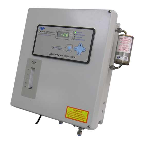
TELEDYNE API 465L User Manual (91 pages)
OZONE MONITOR
Brand:
TELEDYNE API
| Category:
Monitor
| Size: 1 MB
Table of Contents
About this Manual
7
Table of Contents
9
Introduction
13
Specifications and Agency Approvals
15
Specifications
15
Approvals
16
Safety
16
Emc
16
Other Type Certifications
17
Principle of Operation
19
Getting Started
21
Wiring Requirements for Nema Enclosures
22
Figure 4-1: Mounting Hole Locations and Dimensions
22
Wiring Instructions
23
Figure 4-2: NEMA AC Power Connection to Monitor
23
Pneumatic Connections
24
Figure 4-3: Pneumatic Connections, Rack Mount Configuration
24
Figure 4-4: Pneumatic Connections, NEMA Configuration, Single Stream
25
Figure 4-5: Pneumatic Connections, NEMA Configuration, Multi-Stream
25
Sample Gas Connection
26
Figure 4-6: 465L Pneumatic Diagram with Sample Conditioner and Permeation Gas Dryer Options (in Single-Stream Configuration)
27
Exhaust Connection
30
Figure 4-7: Rear Panel Electrical I/O Connections
30
Figure 4-8: NEMA Electrical I/O Connections
30
Electrical I/O Connections
31
Location of I/O Connectors in the NEMA Configuration
31
Analog Output
31
Status Outputs
31
Figure 4-9: Status Output Schematic
32
Table 4-1: Status Output Definitions
32
Hi-Current Relay Outputs
33
Table 4-2: Relay Functions for Single Stream Config
33
Table 4-3: Relay Functions for Multi-Stream Configs
33
Multi-Stream Relay Outputs (Optional)
34
Table 4-4: Multi-Stream Relays
34
Digital Serial Interfaces
35
Frequently Asked Questions
37
Options
39
Stream Selector (3 or 6 Stream)
39
Disposable Sample Inlet Filters
39
Rack Mount Slides
39
Electronic Flowmeter
39
Sample Conditioner
39
Permeation Gas Dryer
39
Operation
41
Front Panel Overview
41
Ozone Concentration Display
41
Menu Navigation Keypad
41
Figure 7-1: Front Panel Display
41
Stream Selector Status/Control (Optional)
42
Concentration Alarm Status/Reset
42
Table 7-1: Alarm Led's
42
Status Leds
43
Front Panel Menus
43
Menu Navigation Basics
43
Table 7-2: Status Led's
43
Editing Numeric Values
44
Figure 7-2: Front Panel Menu Diagram
45
Figure 7-3: Front Panel Menu Diagram
46
DIAG Menu
47
Table 7-3: Analog Step Test Values
47
Table 7-4: Signal I/O List
48
Figure 7-4: Span Cal Menu
51
Figure 7-5: Flow Cal Menu
51
VIEW Menu
52
CONFIG Menu
52
Table 7-5: VIEW Menu Parameters
52
Table 7-6: CONFIG Menu Parameters
52
SETUP-VARS Menu
53
Table 7-7: VARS List
53
SETUP-STREAM Menu
54
Table 7-8: STREAM Properties
54
Multi-Stream Operation
55
Digital Communications
57
Digital Communications Overview
57
Changing Com Port Hardware Configuration
57
Figure 8-1: Com Configuration Jumper Settings (SW2)
58
Rs-232 Configuration
59
Table 8-1: RS-232 Connector Details
59
Table 8-2: RS-232 Port Setup
59
Rs-485 Configuration
60
Table 8-3: RS-485 Connector Details
60
Table 8-4: RS-485 Port Setup
60
Ethernet Configuration
61
Hardware Setup for Configuring the Ethernet Module
61
Verifying Network Hardware Connection
61
Table 8-5: Ethernet LED Definitions
61
Determining a Dynamically Assigned IP Address (DHCP Mode)
62
Manually Assigning a Static IP Address
62
Modbus Register Maps
63
MODBUS Commands Supported
63
Notes on MODBUS Registers
63
Table 8-6: Supported MODBUS Commands
63
Real-Time Concentration and Status Registers (Read Only)
64
Instrument Setup and Configuration Registers (Read / Write)
65
Maintenance and Adjustments
67
Maintenance Schedule
67
Table 9-1: Maintenance Schedule
67
Instrument Layout
68
Figure 9-1: Instrument Layout, Rack Mount Configuration
68
Replacing Internal Particulate Filter
69
Figure 9-2: Instrument Layout, NEMA Configuration
69
Uv Lamp Adjustment
70
Uv Lamp Replacement
71
Sample Pump Replacement
72
Sensor Valve Replacement
73
Figure 9-3: Sensor Detail
73
Water Drop-Out Filter (Option) Maintenance
74
Particulate Filter Replacement
74
Configuring the Analog Output
74
Cleaning Exterior Surfaces of the 465L
75
Boot Loader Operation
75
Figure 9-4: Mainboard - Analog Output Configuration
75
Boot Loader - Hardware Setup
76
Boot Loader - Software Setup
76
Table 9-2: Required Software
76
Troubleshooting
79
Reference Drawings
79
Pneumatic Diagram
79
Figure 10-1: Pneumatic Diagram, 3 Stream Configuration
79
Interconnect Diagram
80
Figure 10-2: Interconnect Diagram
80
Troubleshooting with Front Panel Status Led's or Status Outputs
81
Table 10-1: Status Led/Output Definitions
81
Sensor OK
82
Invalid Reading
82
Check Lamp
82
Pneumatic Error
82
Calibration
85
Factory Calibration
85
Zero Calibration
85
Spare Parts
87
465L Rack Mount Spare Parts List
87
List
88
Advertisement
Advertisement
Related Products
TELEDYNE API 465H
TELEDYNE API Everywhereyoulook 480H
TELEDYNE API 452
TELEDYNE API 470
TELEDYNE API 480L
TELEDYNE API 480M
TELEDYNE API 465M
TELEDYNE API Categories
Measuring Instruments
Accessories
Monitor
Recording Equipment
Portable Generator
More TELEDYNE API Manuals
Login
Sign In
OR
Sign in with Facebook
Sign in with Google
Upload manual
Upload from disk
Upload from URL