Tektronix TSG 601 Manuals
Manuals and User Guides for Tektronix TSG 601. We have 3 Tektronix TSG 601 manuals available for free PDF download: Service Manual, User Manual, Instructions
Advertisement

Tektronix TSG 601 User Manual (70 pages)
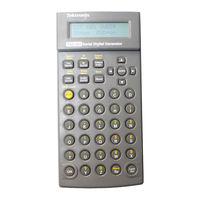
Serial Digital Generator
Brand: Tektronix
|
Category: Test Equipment
|
Size: 0 MB
Table of Contents

Tektronix TSG 601 Instructions (2 pages)
Serial Digital Generator
Brand: Tektronix
|
Category: Portable Generator
|
Size: 0 MB
Table of Contents
Advertisement