Sign In
Upload
Manuals
Brands
Tektronix Manuals
Measuring Instruments
TDS7104
Tektronix TDS7104 Manuals
Manuals and User Guides for Tektronix TDS7104. We have
4
Tektronix TDS7104 manuals available for free PDF download: User Manual, Service Manual, Reference Manual
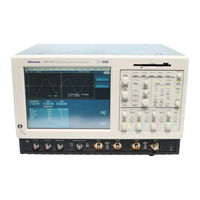
Tektronix TDS7104 User Manual (480 pages)
Communications Signal Analyzers, Digital Phosphor Oscilloscopes, Digital Storage Oscilloscopes
Brand:
Tektronix
| Category:
Measuring Instruments
| Size: 5.17 MB
Table of Contents
Table of Contents
5
List of Tables
15
General Safety Summary
17
About this Manual
19
Preface
19
Related Manuals and Online Documents
20
Contacting Tektronix
21
Models
23
Product Description
23
Key Features
24
Product Software
25
Software Upgrade
26
Installation
27
Unpacking
28
Checking the Environment Requirements
29
Connecting Peripherals
29
Figure 1- 1: Locations of Peripheral Connectors on Rear Panel
30
Powering on the Instrument
31
Table 1- 1: Additional Accessory Connection Information
31
Table 1- 2: Line Fuses
31
Figure 1- 2: Powering on the Instrument
32
Shutting down the Instrument
32
Backing up User Files
33
Creating an Emergency Startup Disk
33
Installing Software
34
Enabling Your LAN and Connecting to a Network
37
Figure 1- 3: Enabling Your LAN and Connecting to a Network
37
Figure 1- 4: Setting up a Dual Display
39
Setting up a Dual Display
39
Figure 1- 5: Drag Area for Windows Task Bar
41
Figure 1- 6: Moving Windows Desktop Icons to the External Monitor
41
Assemble Equipment
43
Incoming Inspection
43
Self Tests
44
Functional Tests
45
Check Vertical Operation
46
Figure 1- -7: Universal Test Hookup for Functional Tests - - CH
47
Figure 1- 8: Channel Button Location
48
Table 1- 3: Vertical Settings
48
Check Horizontal Operation
50
Figure 1- 9: Setup for Time Base Test
50
Check Trigger Operation
52
Figure 1- 10: Setup for Trigger Test
53
Check File System
54
Figure 1- 11: Setup for the File System Test
55
Perform the Extended Diagnostics
57
Accessories & Options
59
Options
59
Table 1- 4: Options
59
Accessories 1
60
Accessories
61
Table 1- 5: Standard Accessories
61
Table 1- 6: Optional Accessories
63
Operational Maps
67
Documentation Map
68
Functional Model Map
70
System Overview Maps
70
Process Overview Map
72
User Interface Map - - Complete Control and Display
73
Front-Panel Map - - Quick Access to most Often Used Features
74
Display Map - - Single Graticule
75
Front Panel I/O Map
76
Rear Panel I/O Map
77
Overview
79
Acquiring Waveforms
85
Signal Connection and Conditioning
86
Figure 3- 1: Input and Acquisition Systems and Controls
87
Connecting and Conditioning Your Signals
88
To Set up Signal Input
92
To Autoset the Instrument
95
To Reset the Instrument
96
To Get more Help
97
Input Conditioning Background
97
Figure 3- -2: Setting Vertical Range and Position of Input
100
Figure 3- 3: Varying Offset Moves the Vertical Acquisition Window on the Waveform
101
Figure 3- 4: Horizontal Acquisition Window Definition
102
Figure 3- 5: Common Trigger, Record Length, and Acquisition Rate for All Channels
104
Using the Acquisition Controls
106
Table 3- 1: Additional Resolution Bits
107
Figure 3- 6: Roll Mode
110
Figure 3- 7: Aliasing
111
To Set Acquisition Modes
112
To Start and Stop Acquisition 3
115
To Set Roll Mode
116
Setting Acquisition Controls
104
Acquisition Control Background
117
Acquisition Hardware
118
Sampling Process
118
Figure 3- 8: Digitizer Configuration
118
Figure 3- 9: Digital Acquisition - Sampling and Digitizing
118
Acquisition Modes
119
Waveform Record
119
Real-Time Sampling
120
Figure 3- 10: the Waveform Record and Its Defining Parameters
120
Figure 3- 11: Real-Time Sampling
120
Equivalent-Time Sampling 3
121
Equivalent-Time Sampling
122
Table 3- 2: Sampling Mode Selection
122
Interpolation
123
Figure 3- 12: Equivalent-Time Sampling
123
Interleaving
124
Table 3- 3: How Interleaving Affects Sample Rate
124
Using Fast Acquisition Mode
125
Using Fast Acquisitions
126
Figure 3- -13: Normal DSO Acquisition and Display Mode Versus
127
Figure 3- -14: Normal DSO and Fast Acquisition Displays 3
128
To Turn Fast Acquisitions on and off 3
129
To Set Display Format
132
Table 3- 4: XY and XYZ Format Assignments
133
Using Fastframe
134
Using Fastframe Acquisitions
135
To Set Fastframe Mode
136
Time Stamping Frames
138
Figure 3- -17: Fastframe Time Stamp 3
140
O/E Converter
141
Attenuating Optical Signals
142
Front Panel Connectors
142
Optical Input Connector
142
Output Connectors
142
O/E Electrical Out-To-Ch1 Input Adapter 3
143
O/E-To-SMA Adapter
144
Cleaning Optical Connectors
144
Compensation
145
Wavelength, Filter, and Bandwidth Selection
145
Optical Dark Compensation 3
145
Optical Bandwidth
146
Bandwidth for Unfiltered Settings
148
Bandwidth for Reference Receiver Settings
148
Triggering
149
Triggering Concepts
150
The Trigger Event
151
Trigger Sources
151
Trigger Types
151
Trigger Modes
152
Trigger Holdoff
153
Trigger Coupling
154
Horizontal Position
155
Slope and Level
155
Delayed Trigger System
156
Triggering from the Front Panel
156
Access Procedures
156
To Check Trigger Status
160
Additional Trigger Parameters
161
Advanced Triggering
166
Figure 3- -25: Example Advanced Trigger Readout 3
167
Table 3- 5: Pattern and State Logic
169
Figure 3- -26: Violation Zones for Setup/Hold Triggering 3
171
To Trigger on a Glitch
172
To Trigger on a Runt Pulse
174
Trigger Based on Pulse Width
177
To Trigger Based on Transition Time
180
Trigger Based on Pulse Timeout 3
182
Trigger on a Pattern 3
183
Trigger on a Pattern
186
To Trigger on a State
187
To Trigger on Setup/Hold Time Violations
188
Sequential Triggering
191
Using Sequential Triggering
192
Figure 3- -28: Triggering with Horizontal Delay off 3
193
Figure 3- -29: Triggering with Horizontal Delay on 3
194
Figure 3- -30: Trigger and Horizontal Delay Summary 3
195
To Trigger on a Sequence
196
Comm Triggering
200
Serial Pattern Triggering
200
Displaying Waveforms
201
Using the Waveform Display
202
Using the Display
203
Table 3- 6: Defining and Displaying Waveforms
204
Table 3- 7: Operations Performed Based on the Waveform Type
204
Figure 3- -32: Horizontal Position Includes Time to Horizontal Reference 3
206
To Display Waveforms in the Main Graticule 3
207
Setting Multiview Zoom Controls
209
Using with Waveforms
210
To Zoom Waveforms
211
Customizing the Display
216
Table 3- 8: Customizable Display Elements
216
Set Display Styles
219
Customize Graticule and Waveforms 3
222
Measuring Waveforms
225
Taking Automatic Measurements
226
Figure 3- -34: Annotated Display 3
227
Using Automatic Measurements
228
Figure 3- -35: High/Low Tracking Methods 3
229
Figure 3- -36: Reference-Level Calculation Methods 3
230
To Take Automatic Measurements 3
231
To Localize a Measurement
237
Taking Cursor Measurements
238
Table 3- 9: Cursor Functions (Types)
239
Using Cursors
240
Figure 3- -38: Components Determining Time Cursor Readout Values 3
242
To Set the Cursor Sources
243
Table 3- 10: Cursor Units
243
Taking Histograms
246
Using Histograms
247
To Start and Reset Histogram Counting
247
Histogram Measurements
249
Optimizing Measurement Accuracy
249
To Compensate the Instrument
250
To Connect the Probe Calibration Fixture
252
To Calibrate Probes
255
To Compensate Passive Probes
259
To Deskew Channels
259
Serial Mask Testing
262
Creating and Using Math Waveforms
263
Defining Math Waveforms
264
Using Math
266
Table 3- 11: Math Expressions and the Math Waveforms Produced
266
Figure 3- -43: Derivative Math Waveform 3
269
Figure 3- -44: Peak-Peak Amplitude Measurement of a Derivative Waveform 3
270
To Define a Math Waveform 3
272
Operations on Math Waveforms
275
Using Math Waveforms
275
To Use Math Waveforms
277
Defining Spectral Math Waveforms
280
Using Spectral Math Controls
281
Table 3- 12: Spectral Analyzer Controls
281
Figure 3- -45: Duration and Resolution Control Effects 3
283
Figure 3- -46: Definition of Gate Parameters 3
284
Figure 3- -47: Effects of Frequency Domain Control Adjustments 3
287
Figure 3- -48: Effects of Adjusting the Reference Level 3
289
Figure 3- -50: Example of the Effects of Setting the Phase Suppression Threshold 3
291
Figure 3- -51: Windowing the Time Domain Record 3
293
Table 3- 13: Window Characteristics
294
Figure 3- -52: Example of Scallop Loss for a Hanning Window Without Zero Fill 3
295
Figure 3- -53: Time and Frequency Graphs for the Gaussian Window 3
297
Figure 3- -54: Time and Frequency Domain Graphs for the Rectangular Window 3
298
Figure 3- -55: Time and Frequency Graphs of the Hamming Window 3
299
Figure 3- -56: Time and Frequency Graphs for the Hanning Window 3
300
Figure 3- -57: Time and Frequency Graphs for the Kaiser-Bessel Window 3
301
Figure 3- -58: Time and Frequency Graphs of the Blackman-Harris Window 3
302
Figure 3- -59: Time and Frequency Domain Graphs for the Flattop2 Window 3
303
Figure 3- -60: Tek Exponential Window in the Time and the Frequency Domains 3
304
Recognizing Aliasing
305
Figure 3- -61: How Aliased Frequencies Appear in a Spectral Waveform 3
306
To Select a Predefined Spectral Math Waveform 3
308
To Define a Spectral Math Waveform 3
309
To Define a Spectral Math Waveform
312
Spectral Math Example
317
Data Input/Output
323
Saving and Recalling a Setup
323
Figure 3- -62: Auto-Increment File Name Feature 3
325
To Save Your Setup
326
Using Auto-Increment File Name 3
328
To Recall Your Setup
329
Saving and Recalling Waveforms
331
To Save Your Waveform
332
To Recall Your Waveform
335
To Clear References
338
Exporting and Copying Waveforms
340
To Export Your Waveform
341
To Use an Exported Waveform 3
349
To Copy Your Waveform
351
Printing Waveforms
355
To Print from Front Panel
355
To Print from Menu Bar
355
To Set up the Page
356
Figure 3- -64: Hardcopy Formats 3
356
To Preview the Page
357
To Print Using Print Screen 3
358
To Date/Time Stamp Hardcopies
359
Remote Communication
360
Accessing Online Help
361
How to Use Online Help
362
Appendix A: Specifications
367
Product and Feature Description
368
Table A- 1: Instrument Models
368
Display Features
369
Measurement Features
370
Trigger Features
370
Convenience Features
371
Specification Tables
372
Table A- 2: Channel Input and Vertical Specifications
372
Table A- 3: Horizontal and Acquisition System Specifications
384
Table A- 4: Trigger Specifications
390
Table A- 5: Display Specifications
396
Table A- 6: Input/Output Port Specifications
397
Table A- -7: O/E Converter (CSA7000 Series Only
400
Table A- 8: Data Storage Specifications
402
Table A- 9: Power Source Specifications
403
Appendix B: Automatic Measurements Supported
409
Levels Used in Taking Amplitude, Timing, and Area Measurements
413
Levels Used in Taking Eye Measurements (Optional on TDS7000 Series & TDS6000 Series)
414
DCD Values
416
Measurements Annotations
417
Appendix C: Menu Bar Commands
423
File Commands
423
Edit Commands
425
Vertical Commands
426
Horizontal and Acquisition Commands
427
Trigger Commands
429
Display Commands
431
Cursors Commands
433
Measure Commands
433
Masks Commands
435
Math Commands
436
Utilities Commands
437
Help Commands
438
Appendix D: Cleaning
439
Exterior Cleaning
439
Flat Panel Display Cleaning
440
Glossary
441
Channels
443
Fast Acquisition Mode
445
Advertisement
Tektronix TDS7104 User Manual (395 pages)
TDS7000 Series Digital Phosphor Oscilloscopes
Brand:
Tektronix
| Category:
Test Equipment
| Size: 4.43 MB
Table of Contents
Table of Contents
6
List of Tables
14
General Safety Summary
16
Symbols and Terms
17
About this Manual
18
Preface
18
Related Manuals and Online Documents
19
Contacting Tektronix
20
Key Features
22
Models
22
Product Description
22
Product Software
23
Firmware Upgrade
24
Probes Supported
25
Table 1- 1: Recommended Probe Cross Reference
25
Installation
26
Unpacking
26
Checking the Environment Requirements
27
Connecting Peripherals
27
Figure 1- 1: Locations of Peripheral Connectors on Rear Panel
28
Figure 1- 2: Line Fuse and Power Cord Connector Locations, Rear Panel
29
Powering on the Oscilloscope
29
Table 1- 2: Additional Accessory Connection Information
29
Table 1- 3: Line Fuses
29
Figure 1- 3: On/Standby Switch Location
30
Shutting down the Oscilloscope
30
Backing up User Files
31
Creating an Emergency Startup Disk
31
Installing Software
32
Enabling Your LAN and Connecting to a Network
35
Setting up a Dual Display
35
Figure 1- 4: Drag Area for Windows Task Bar
37
Assemble Equipment
38
Incoming Inspection
38
Self Tests
38
Functional Tests
39
Figure 1- 5: Universal Test Hookup for Functional Tests - CH 1 Shown
40
Figure 1- 6: Channel Button Location
41
Figure 1- 7: Setup for Time Base Test
42
Figure 1- 8: Setup for Trigger Test
44
Figure 1- 9: Setup for the File System Test
46
Perform the Extended Diagnostics
47
Accessories & Options
50
Options
50
Accessories
51
Table 1- 4: Standard Accessories
51
Table 1- 5: Optional Accessories
52
Documentation Map
55
Functional Model Map
56
System Overview Maps
56
Process Overview Map
58
User Interface Map - - Complete Control and Display
59
Front Panel Map - - Quick Access to most Often Used Features
60
Display Map - - Single Graticule
61
Front Panel I/O Map
62
Rear Panel I/O Map
63
Acquiring Waveforms
64
Overview
64
Signal Connection and Conditioning
64
To Autoset the Oscilloscope
64
Acquiring Waveforms 3
66
Figure 3- 1: Input & Acquisition Systems & Controls
67
Signal Connection and Conditioning 3
67
Connecting and Conditioning Your Signals 3
68
To Set up Signal Input 3
71
To Autoset the Oscilloscope 3
74
To Reset the Oscilloscope
75
To Get more Help
76
Figure 3- 2: Setting Vertical Range and Position of Input Channels
79
Figure 3- 3: Varying Offset Moves the Vertical Acquisition Window on the Waveform
80
Figure 3- 4: Horizontal Acquisition Window Definition
81
Figure 3- 5: Common Trigger, Record Length, and Acquisition Rate for All Channels
83
Setting Acquisition Controls
84
Using the Acquisition Controls
85
Table 3- 1: Additional Resolution Bits
86
Figure 3- 6: Roll Mode
89
To Set Acquisition Modes
90
Figure 3- 7: Aliasing
90
To Start & Stop Acquisition 3
92
Acquisition Control Background
95
Acquisition Hardware
95
Figure 3- 8: Digitizer Configuration
96
Figure 3- 9: Digital Acquisition - Sampling and Digitizing
96
Sampling Process 3
96
Waveform Record
97
Figure 3- 10: the Waveform Record and Its Defining Parameters
97
Real-Time Sampling
98
Figure 3- 11: Real-Time Sampling
98
Figure 3- -12: Equivalent-Time Sampling
98
Table 3- 2: Sampling Mode Selection
99
Interpolation
100
Interleaving
100
Table 3- 3: How Interleaving Affects Sample Rate
101
Using Fast Acquisitions
102
Figure 3- 13: Normal DSO and Fast Acquisition Displays
103
Figure 3- 14: Normal DSO Acquisition and Display Mode Versus Fast Acquisition Mode
104
To Turn Fast Acquisitions on and off
105
Figure 3- 15: Fast Acquisition XY Display
108
To Set Display Format
109
Using Fast Acquisition Mode
101
Figure 3- 16: Fastframe
109
Table 3- 4: XY Format Pairs
109
Using Fastframe Acquisitions
110
To Set Fastframe Mode
111
Time Stamping Frames
112
Figure 3- 17: Fastframe Time Stamp
114
Using Fastframe
109
Triggering
116
Triggering Concepts
117
The Trigger Event
117
Trigger Sources
117
Figure 3- 18: Triggered Versus Untriggered Displays
117
Trigger Types
118
Trigger Modes
118
Trigger Holdoff
119
Figure 3- 19: Triggered Versus Untriggered Displays
119
Trigger Coupling
120
Horizontal Position
120
Slope and Level
120
Figure 3- 20: Holdoff Adjustment Can Prevent False Triggers
120
Delayed Trigger System
121
Triggering from the Front Panel
121
Access Procedures
121
Figure 3- 21: Slope and Level Controls Help Define the Trigger
121
To Check Trigger Status
125
Additional Trigger Parameters
127
Advanced Triggering
131
Table 3- 5: Pattern and State Logic
133
Figure 3- -23: Violation Zones for Setup/Hold Triggering 3
135
To Trigger on a Glitch
137
To Trigger on a Runt Pulse
138
Trigger Based on Pulse Width 3
140
To Trigger Based on Transition Time 3
142
To Trigger Based on Transition Time
144
Trigger Based on Pulse Timeout 3
145
Trigger on a Pattern
147
To Trigger on a State
150
To Trigger on Setup/Hold Time Violations 3
151
Figure 3- -24: Triggering on a Setup/Hold Time Violation 3
154
Sequential Triggering
155
Figure 3- -25: Triggering with Horizontal Delay off 3
156
Figure 3- -26: Triggering with Horizontal Delay on 3
157
Figure 3- -27: Trigger and Horizontal Delay Summary 3
158
To Trigger on a Sequence
159
Comm Triggering
162
Displaying Waveforms
164
Using the Waveform Display
165
Using the Display
166
Table 3- 6: Defining and Displaying Waveforms
167
Table 3- 7: Operations Performed Based on the Waveform Type
167
Figure 3- -29: Horizontal Position Includes Time to Horizontal Reference 3
169
To Display Waveforms in the Main Graticule 3
170
Setting Zoom Controls
172
Using with Waveforms
172
To Zoom Waveforms
172
Customizing the Display
177
Using Display Controls
177
Table 3- 8: Customizable Display Elements
177
Set Display Styles
180
Customize Graticule & Waveforms 3
182
Measuring Waveforms
184
Taking Automatic Measurements
185
Figure 3- -31: Annotated Display 3
186
Using Automatic Measurements
187
Figure 3- -32: High/Low Tracking Methods 3
188
Figure 3- -33: Reference-Level Calculation Methods 3
189
To Take Automatic Measurements
190
To Localize a Measurement 3
193
Table 3- 9: Cursor Functions (Types)
195
Using Cursors
196
Figure 3- -35: Components Determining Time Cursor Readout Values 3
197
Table 3- 10: Cursor Units
198
To Set the Cursor Sources
199
Taking Cursor Measurements
195
Taking Histograms
201
Using Histograms
202
To Start and Reset Histogram Counting 3
203
Optimizing Measurement Accuracy
204
Histogram Measurements 3
204
To Compensate the Oscilloscope
205
To Connect the Probe Calibration Fixture
206
To Calibrate Probes
209
To Compensate Passive Probes
211
To Deskew Channels
211
Serial Mask Testing (Option SM Only)
215
Creating and Using Math Waveforms
216
Defining Math Waveforms
217
Using Math
218
Table 3- 11: Math Expressions and the Math Waveforms Produced
219
Figure 3- -40: Derivative Math Waveform 3
221
Figure 3- -41: Peak-Peak Amplitude Measurement of a Derivative Waveform 3
222
To Define a Math Waveform
223
Operations on Math Waveforms
226
Using Math Waveforms
227
To Use Math Waveforms
227
Defining Spectral Math Waveforms
231
Using Spectral Math Controls
232
Table 3- 12: Spectral Analyzer Controls
232
Figure 3- -42: Duration and Resolution Control Effects 3
233
Figure 3- -43: Definition of Gate Parameters 3
234
Figure 3- -44: Affects of Frequency Domain Control Adjustments 3
236
Figure 3- -45: Effects of Adjusting the Reference Level 3
237
Figure 3- -46: Effects of Adjusting the Reference Level Offset Control 3
238
Figure 3- -47: Example of the Effects of Setting the Phase Suppression Threshold 3
240
Figure 3- -48: Windowing the Time Domain Record 3
242
Table 3- 13: Window Characteristics
243
Figure 3- -49: Example of Scallop Loss for a Hanning Window Without Zero Fill 3
244
Figure 3- -50: Time and Frequency Graphs for the Gaussian Window 3
245
Figure 3- -51: Time and Frequency Domain Graphs for the Rectangular Window 3
246
Figure 3- -52: Time and Frequency Graphs of the Hamming Window 3
247
Hanning Window 3
248
Figure 3- -54: Time and Frequency Graphs for the Kaiser-Bessel Window 3
249
Figure 3- -55: Time and Frequency Graphs of the Blackman-Harris Window 3
250
Figure 3- -56: Time and Frequency Domain Graphs for the Flattop2 Window 3
251
Figure 3- -57: Tek Exponential Window in the Time and the Frequency Domains 3
252
Recognizing Aliasing
253
Figure 3- -58: How Aliased Frequencies Appear in a Spectral Waveform 3
254
To Select a Predefined Spectral Math Waveform
255
To Define a Spectral Math Waveform 3
256
To Define a Spectral Math Waveform
262
Data Input/Output
268
Saving and Recalling a Setup
268
Figure 3- -59: Auto-Increment File Name Feature 3
270
To Save Your Setup
271
To Recall Your Setup
274
Saving and Recalling Waveforms
276
To Save Your Waveform
277
To Recall Your Waveform
281
To Clear References
283
Exporting and Copying Waveforms
286
To Export Your Waveform
287
To Use an Exported Waveform 3
295
To Copy Your Waveform
297
Printing Waveforms
301
To Print from Front Panel
301
To Print from Menu Bar
301
To Set up the Page
301
Figure 3- -61: Hardcopy Formats 3
302
To Preview the Page
303
Figure 3- -63: Print Preview Window 3
304
To Date/Time Stamp Hardcopies
305
Remote Communication
306
Accessing Online Help
308
How to Use Online Help
308
Appendix A: Specifications
312
Product and Feature Description
312
Table A- 1: TDS7000 Models
312
Acquisition Features
313
Display Features
314
Specification Tables
315
Table A- 2: Channel Input and Vertical Specifications
315
Table A- 3: Horizontal and Acquisition System Specifications
320
Table A- 4: Trigger Specifications
324
Table A- 5: Display Specifications
327
Table A- 6: Input/Output Port Specifications
328
Table A- 7: Data Storage Specifications
330
Table A- 8: Power Source Specifications
330
Table A- 9: Mechanical Specifications
331
Table A- 10: Environmental Specifications
332
Table A- 11: Certifications and Compliances
333
Appendix B: Automatic Measurements Supported
336
Table B- 1: Supported Measurements and Their Definition
336
Table B- -2: Supported Mask Measurements and Their Definition (Option SM Only
338
Levels Used in Taking Amplitude, Timing, and Area Measurements
339
Levels Used in Taking Eye Measurements (Option SM Only)
341
P Values
341
T1 Values
342
T2 Values
342
DCD Values
342
Appendix C: Cleaning
344
Exterior Cleaning
344
Flat Panel Display Cleaning
344
Appendix D: Menu Bar Commands
346
File Commands
346
Edit Commands
348
Trigger Commands
350
Display Commands
351
Measure Commands
354
Math Commands
356
Tektronix TDS7104 Service Manual (254 pages)
TDS7000 Series, Digital Phosphor
Brand:
Tektronix
| Category:
Test Equipment
| Size: 4.56 MB
Table of Contents
Table of Contents
5
List of Tables
12
General Safety Summary
15
Service Safety Summary
17
Manual Conventions
19
Manual Structure
19
Preface
19
Related Documentation
20
Contacting Tektronix
21
Specifications
23
Product and Feature Description
23
Table 1- 1: TDS7000 Models
23
Acquisition Features
24
Display Features
25
Measurement Features
25
Trigger Features
25
Convenience Features
26
Specification Tables
27
Table 1- 2: Channel Input and Vertical Specifications
27
Table 1- 3: Horizontal and Acquisition System Specifications
32
Table 1- 4: Trigger Specifications
34
Table 1- 5: Display Specifications
37
Table 1- 6: Input/Output Port Specifications
38
Table 1- 7: Data Storage Specifications
40
Table 1- 8: Power Source Specifications
40
Table 1- 9: Mechanical Specifications
41
Table 1- 10: Environmental Specifications
42
Table 1- 11: Certifications and Compliances
43
Operating Information
45
Installation
45
Before You Start
45
Connect the Peripherals
46
Table 2- 1: Additional Accessory Connection Information
46
Figure 2- 1: Locations of Peripheral Connectors on Rear Panel
47
Power on the Instrument
48
Figure 2- 2: Line Fuse and Power Cord Connector Locations, Rear Panel
48
Table 2- 2: Line Fuses
48
Powering off the Oscilloscope
49
Create an Emergency Startup Disk
49
Figure 2- 3: On/Standby Switch Location
49
Software Installation
50
Operating Information
51
Back up User Files
51
User Interface Map
51
Front Panel Controls Map
53
Front Panel I/O Map
54
Instrument Diagnostics
54
Signal Path Compensation
54
Using the Online Help
55
Theory of Operation
57
Logic Conventions
57
Module Overviews
57
General
57
Input Signal Path
57
Display Panel
58
Front Panel
58
Rear Panel
59
Low Voltage Power Supply
59
Fans
59
Performance Verification
61
Conventions
62
Figure 4- 1: Toolbar and Menu Bar
63
Brief Procedures
65
Self Tests
65
Functional Tests
66
Verify All Input Channels
67
Figure 4- 2: Universal Test Hookup for Functional Tests - CH 1 Shown
67
Figure 4- 3: Channel Button Location
68
Verify the Time Base
70
Figure 4- 4: Setup for Time Base Test
70
Verify the a (Main) and B (Delayed) Trigger Systems
72
Figure 4- 5: Setup for Trigger Test
72
Verify the File System
73
Figure 4- 6: Setup for the File System Test
74
Performance Tests - Semi-Automated Method
77
Table 4- 1: Required Equipment and Materials
77
Overview of the Procedure
79
Table 4- 2: Test Sequence Overview
79
Initial Instrumentation Setup
80
Figure 4- 7: Initial Setup
80
Table 4- 3: GPIB Devices Required by Test Program
81
Test Program Installation
82
Test Program Execution
83
Figure 4- 8: Setup to Characterize Signal Source Outputs
83
Figure 4- 9: Setup to Check Delay between Channels
84
Figure 4- 10: Setup to Check Delta Time Accuracy
84
Performance Tests 4
84
Figure 4- 11: Setup to Check Probe Compensation Output
85
Figure 4- 12: Setup to Check Analog Signal Output
85
Figure 4- 13: Setup to Check Auxiliary Output
85
Performance Tests
87
Prerequisites
87
Equipment Required
88
Table 4- 4: Test Equipment
88
TDS7000 Test Record
90
Signal Acquisition System Checks
95
Check DC Voltage Measurement Accuracy
95
Figure 4- 14: Initial Test Hookup
96
Table 4- 5: DC Voltage Measurement Accuracy
97
Figure 4- 15: Measurement of DC Accuracy at Maximum Offset and Position
98
Check DC Gain Accuracy
99
Figure 4- 16: Initial Test Hookup
99
Table 4- 6: Gain Accuracy
101
Figure 4- 17: Measurement of DC Gain Accuracy
102
Check Analog Bandwidth
103
Figure 4- 18: Initial Test Hookup
104
Figure 4- 19: Optional Initial Test Hookup
104
Table 4- 7: Analog Bandwidth
106
Figure 4- 20: Measurement of Analog Bandwidth
107
Check Delay between Channels
108
Figure 4- 21: Initial Test Hookup
109
Figure 4- 22: Measurement of Channel Delay
111
Check Channel Isolation (Crosstalk)
112
Table 4- 8: Delay between Channels Worksheet
112
Figure 4- 23: Initial Test Hookup
113
Time Base System Checks
117
Figure 4- 24: Initial Test Hookup
117
Figure 4- 25: Measurement of Accuracy - Long-Term and Delay Time
119
Figure 4- 26: Initial Test Hookup for External Reference
120
Reference
121
Figure 4- 27: Final Test Hookup for External Reference Input
121
Check Delta Time Measurement Accuracy
122
Figure 4- 28: Delta Time Accuracy Test Hookup
122
Table 4- 9: Delta Time Measurement
124
Trigger System Checks
125
Check Time Accuracy for Pulse, Glitch, Timeout, and Width Triggering
125
Check Sensitivity, Edge Trigger, DC Coupled 4
129
Output Signal Checks
134
Check Probe Compensation Output 4
137
Sine Wave Generator Leveling Procedure
141
Adjustment Procedures
145
Adjustment Interval
145
Adjustment Environment
145
Adjustment Dependencies
145
Adjustment after Repair
145
Table 5- 1: Adjustments Required for Module Replaced
145
Required Equipment
146
Table 5- 2: Required Equipment and Materials
146
Overview of the Procedure
147
Instrumentation Setup
148
Table 5- 3: GPIB Devices Required by Test Program
150
Table 5- 4: Renaming the GPIB Devices
152
Adjustment Program Installation
153
Table 5- 5: Setting the GPIB Addresses
153
Adjustment Program Execution
154
Maintenance
155
Preventing ESD
155
Inspection and Cleaning
156
General Care
156
Interior Cleaning
156
Exterior Cleaning
156
Flat Panel Display Cleaning
157
Table 6- 1: External Inspection Check List
157
Table 6- 2: Internal Inspection Check List
158
Removal and Installation Procedures 6
158
Removal and Installation Procedures
161
Preparation
161
Table 6- -3: Tools Required for Module Removal
162
Procedures for External Modules
163
Procedures for Outer-Chassis Modules
174
Troubleshooting
205
Check for Common Problems
205
Table 6- -4: Failure Symptoms and Possible Causes
205
Equipment Required
207
Fault Isolation Procedure
207
Table 6- -5: Power Supply Voltages
210
PPC and NLX PC Diagnostics
212
Firmware Updates
216
After Repair
217
BIOS Error Messages (Bali NLX)
217
BIOS Error Messages (Radisys NLX)
218
BIOS Beep Codes (Bali NLX)
221
BIOS Beep Codes (Radisys NLX)
222
Dip Switch Controls
222
Diagnostic LED
223
Troubleshooting Using Reset Circuits
225
Update/Restore the NLX Board CMOS
227
Installing an Authorization Key
228
Hard Disk Drive Maintenance
229
Repackaging Instructions
231
Packaging
231
Shipping to the Service Center
231
Options
233
Options and Accessories
233
Accessories
234
Electrical Parts List 8
237
Diagrams 9
239
Parts Ordering Information
241
Using the Replaceable Parts List
242
Advertisement
Tektronix TDS7104 Reference Manual (24 pages)
Digital Storage Oscilloscopes, Communications Signal Analyzers, Digital Phosphor Oscilloscopes
Brand:
Tektronix
| Category:
Test Equipment
| Size: 1.1 MB
Table of Contents
To Use the Front Panel
2
To Use the Screen Interface
3
To Display a Waveform
4
To See more Waveform Detail
5
Use Horizontal Delay
5
To Use Fast Acquisition
6
How Dpos Work
6
To Choose an Acquisition Mode
7
To Select a Trigger
8
Trigger Selections
8
To Use the a (Main) and B (Delayed) Triggers
9
Trigger on B Event
9
B Trigger after Delay Time
9
To Perform Mask Testing
10
To Set up Mask Pass/Fail Testing and View Results
11
To Take Automated Measurements
12
Automated Measurement Selections
12
To Customize an Automated Measurement
13
To Set up a Histogram
13
To Take Measurements with Cursors
14
Other Cursor Measurement Tips
14
To Use Math Waveforms
15
To Use Spectral Analysis
15
To Store Information
16
To Print a Hard Copy
17
To Copy or Export Your Results
17
To Run Application Software
18
To Connect to a Network
19
To Use a Dual Monitor
19
To Access the Help System
20
Front Panel Inputs and Outputs
21
Rear Panel Inputs and Outputs
22
Recommended Probes and Accessories
23
Advertisement
Related Products
Tektronix TDS7404
Tektronix TDS7054
Tektronix TDS7254
Tektronix TDS7154
Tektronix TDS7704B
Tektronix TDS7404B
Tektronix TDS7254B
Tektronix TDS7154B
Tektronix TDSUSB2
Tektronix TDS5032
Tektronix Categories
Test Equipment
Measuring Instruments
Amplifier
Printer
Portable Generator
More Tektronix Manuals
Login
Sign In
OR
Sign in with Facebook
Sign in with Google
Upload manual
Upload from disk
Upload from URL