Sign In
Upload
Manuals
Brands
Tandon Manuals
Storage
TM848-2
Tandon TM848-2 Manuals
Manuals and User Guides for Tandon TM848-2. We have
2
Tandon TM848-2 manuals available for free PDF download: Operating And Service Manual
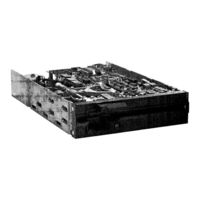
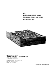
Tandon TM848-2 Operating And Service Manual (90 pages)
OEM DISK DRIVES 48 TRACKS PER INC
Brand:
Tandon
| Category:
Floppy Disk Drive
| Size: 3.97 MB
Table of Contents
Table of Contents
3
1 Introduction
8
Functional Description of the Drive
8
Physical Description of the Drive
8
Purpose of the Drive
8
Section I
8
Introduction Tothetm848 Familyof Disk Drives
8
Diskettes
9
Incoming Inspection Checks and Procedures
9
Interface Circuit Specifications
9
Mechanical and Electrical Sepcifications
9
Mechanical and Electrical Specifications
9
Power Requirements
9
Interface Connections
12
Mounting the Drive
12
Cooling System Requirements
13
Diskette Care, Handling and Storage
13
Dust Cover
13
Hardware "1-6
13
TM848 Disk Drive Mounting Configuration
13
Components of the Drive
14
Operation of the Drive
14
Organization of the Drive
14
Write Protect
14
Drive Status Logic
15
Index Pulse
15
Data Electronics
16
Positioner Control
16
Spindle Drive System
16
TM848 Disk Drive Functional Block Diagram
16
FM Recording Magnetization Profiles
17
Write Operation Timing Diagram
18
Interface Electronics
19
Interface Connector Pin Assignments, P13
19
Power Connector Pin Assignments
19
Read Timing Diagram
19
Drive Select
21
Input Line Terminations from Removable Resistor Pack
21
Power Connector Pin Assignments
21
Program Shunt
21
Terminated Lines
21
Circuit Board Assembly
22
General Control and Data Timing Requirements
23
Options
24
Drive Select DS1--DS4
25
Side Select Options Using Drive Select
25
User-Selectable Options
24
In Use from Drive Select
25
In Use from Head Load
25
Radial Ready
25
Ready Alternate Output Pad
25
Radial Index
26
Radial Ready Installation
26
Ready Modified
26
Disk Change
27
Diskette Lever Lock Latch Option
27
In Use Altenate Output Pad
27
Index Alternate Output Pad
27
Radial Index Installation
27
Two-Sided Diskette Installed
27
1.19.19 Allow Write When Write Protected
28
Radial Head Load Signal
28
Head Side Select Options S1--S3
29
Spindle Motor Control Options
29
Motor Control Select Options MC1--MC4
29
Maintenance Checks and Adjustments
30
Head Load Alternate Output Pad Option
28
Inhibit Write When Write Protected
28
Radial Head Load Signal Option
28
Stepper Power from Drive Select
28
Stepper Power from Head Load Line
28
2 Introduction
30
Long-Term Drive Motor Speed Checks and Adjustments
30
Spindle Drive Motor Checks and Adjustments
30
Cats Eye Alignment Check and Adjustment
31
Circuit Board Assembly
31
Hub Center Line and Track Locations
32
Cats Eye Alignment Check
33
Cats Eye Pattern
33
Head Carriage Adjustment
34
Head Module Retaining and Cam Screws
34
Index Sensor Checks and Adjustments
35
Index-To-Data Burst Checks
35
Index Sensor Adjustment
36
Index-To-Data Burst
36
Index Sensor's Retaining Screw and Adjustment
36
Index Pulse Width Check
37
Track 00 Sensor Check and Adjustment
37
Negative Going Pulse Width
37
Amplitude Check
38
Azimuth Check
39
Optimum Head Azimuth Alignment
40
Load Arm Adjustment
41
Load Arm Adjustment, Front View
41
Printed Circuit Board Operation
42
Interface Electronics Specifications
42
Printed Circuit Board
42
Interface Configuration
42
3 Introduction
42
Physical Description of the Circuit Board
42
Input Control Lines
43
Drive Interface Lines and Pin Connectors
44
Stepper Logic Truth Table
46
Write Data Circuit Block Diagram
47
Trim Erase Diagram
49
Side Select Schematic Diagram
50
Output Control Lines
51
Index Schematic Diagram
52
Track 00 Schematic Diagram
53
Write Protect Schematic Diagram
54
Read Circuit Block Diagram
55
Troubleshooting Guide
57
4 Introduction
57
Not Ready And/Or no Index
58
Will Not Seek or Restore
58
Will Not Read
59
Will Not Write
59
Activity L.E.D. Inoperative
60
Drive Motor will Not Start When Door Latched
60
Drive Belt
61
5 Introduction
61
Replacement Procedures
61
Drive Motor
62
Drive Belt and Spindle
62
Circuit Board
63
Drive Motor and Related Parts
63
Cone Assembly
64
Circuit Board Mounting Screws
64
Cone Assembly Key Parts
65
Cone Assembly Parts
65
Bridge Assembly
66
Diskette Lever Key Parts
66
Diskette Lever Adjustment
67
Bridge Assembly Key Parts
67
Diskette Lever
66
Bezel
68
Bridge Assembly Additional Key Parts
68
Bezel and Related Parts
68
Activity L, E, D
69
Load Arm Assembly
70
Load Arm Assembly Key Parts
70
Write Protect Sensor Assembly
71
Track 00 Sensor Assembly Key Parts
71
Track 00 Sensor Assembly
70
Door Switch Assembly
72
Write Protect Sensor Assembly Key Parts
72
Door Switch Assembly Key Parts
73
Index Sensor Assembly
73
Index Sensor Assembly Key Parts, Top View
73
Diskette Ejector Assembly
74
Index Sensor Assembly Key Parts, Bottom View
74
Load Resistor Assembly
75
Diskette Ejector Assembly Key Parts
75
Load Resistor Assembly and Key Parts
76
Stepper Band
77
Stepper Band Key Parts
77
Stepper Motor Assembly
78
Stepper Band Additional Key Parts
78
Head Carriage Assembly
79
Stepper Motor Assembly Key Parts
79
Drawings
81
Appendix I Printed Circuit Board Schematics and Assembly
88
Appendix II Recommended Spare Parts List
88
Advertisement
tandon TM848-2 Operating And Service Manual (90 pages)
48 TRACKS PER INC
Brand:
tandon
| Category:
Storage
| Size: 6.89 MB
Table of Contents
Table of Contents
4
Mechanical and Electrical Specifications
9
TM848 Disk Drive Functional Block Diagram
16
FM Recording Magnetization Profiles
17
Write Operation Timing Diagram
18
Power Connector Pin Assignments
19
Read Timing Diagram
19
Circuit Board Assembly
22
General Control and Data Timing Requirements
23
Allow Write When Write Protected
24
Head Side Select Options
24
Inhibit Write When Write Protected
24
Options
24
Spindle Motor Control Options
24
Radial Ready Installation
26
Radial Index Installation
27
Radial Head Load Signal
28
Motor Control Select Options MC1 - MC4
29
Power Requirements
11
Figure
13
TM848 Disk Drive Mounting Configuration
13
Disk Change
14
2 Introduction
30
S Pindle Drive Motor Checks and Adjustments
30
Long-Term Drive Motor Speed Checks and Adjustments
30
Cats Eye Alignment Check and Adjustment 2
31
Circuit Board Assembly
31
Hub Center Line and Track Locations
32
Cats Eye Alignment Check
33
Cats Eye Pattern
33
Head Carriage Adjustment
34
Head Module Retaining and Cam Screws
34
Index Sensor Checks and Adjustments
35
Index-To-Data Burst Checks
35
Index Sensor Adjustment
36
Index-To-Data Burst
36
Index Sensor's Retaining Screw and Adjustment
36
Index Pulse Width Check
37
Track 00 Sensor Check and Adjustment
37
Negative Going Pulse Width
37
Amplitude Check
38
Azimuth Check
39
Optimum Head Azimuth Alignment
40
Load Arm Adjustment
41
Load Arm Adjustment, Front View 2-1
41
Section II I
42
Printed Circuit Board O P E R a T Io N
42
3 Introduction
42
Physical Description of the Circuit Board
42
Interface Electronics Specifications
42
Interface Configuration
42
Input Control Lines 3
43
Select Lines Schematic Diagram
43
Drive Interface Lines and Pin Connectors
44
Stepper Logic Truth Table
46
Write Data Circuit Block Diagram
47
Trim Erase Diagram
49
Side Select Schematic Diagram
50
O Utput Control Lines
51
Track 00 Schematic Diagram 3-1
53
Write Protect Schematic Diagram. 3-1
54
Read Circuit Block Diagram
55
Read Data Schematic Diagram
56
Troubleshooting Guide
57
4 Introduction
57
Not Ready And/Or no Index
58
Will Not See Kor Restore
58
Will Not Write
59
Will Not Read
59
Activity L.E.D. Inoperative
59
Drive Motor will Not Start When Door Latched
60
5 Introduction
61
Drive Motor
61
Circuit Board
61
Cone Assembly
61
Drive Belt and Spindle
62
Drive Motor and Related Parts
63
Circuit Board Mounting Screws
64
Cone Assembly Key Parts
65
Cone Assembly Parts
65
Diskette Lever
66
Bridge Assembly
66
Diskette Lever Key Parts
66
Diskette Lever Adjustment
67
Bridge Assembly Key Parts
67
Bezel
68
Bridge Assembly Additional Key Parts
68
Bezel and Related Parts
68
I Activity L. E. D. Key Parts
69
Load Arm Assembly Key Parts
70
Track 00 Sensor
71
Track 00 Sensor Assembly Key Parts 5-1
71
Write Protect Sensor Assembly Key Parts
72
Door Switch Assembly Key Parts
73
Index Sensor Assembly Key Parts, Top View
73
Index Sensor Assembly Key Parts, Bottom View
74
Diskette Ejector Assembly Key Parts
75
Load Resistor Assembly and Key Parts 5-1
76
Stepper Band Key Parts 5-1
77
Stepper Band Additional Key Parts 5-1
77
Stepper Motor Assembly Key Parts
79
Printed Circuit Board
81
Advertisement
Related Products
Tandon TM848-1
Tandon TM603S
Tandon TM603SE
Tandon TM602S
Tandon TM362
Tandon TM262
Tandon TM848-2E
Tandon TM848-1E
Tandon TM 100
Tandon TM100-1
Tandon Categories
Storage
Floppy Disk Drive
DC Drives
More Tandon Manuals
Login
Sign In
OR
Sign in with Facebook
Sign in with Google
Upload manual
Upload from disk
Upload from URL