Sign In
Upload
Manuals
Brands
Takeuchi Manuals
Compact Excavator
TB 250
Takeuchi TB 250 Hydraulic Excavator Manuals
Manuals and User Guides for Takeuchi TB 250 Hydraulic Excavator. We have
2
Takeuchi TB 250 Hydraulic Excavator manuals available for free PDF download: Workshop Manual, Operator's Manual
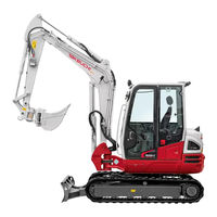
Takeuchi TB 250 Workshop Manual (353 pages)
Brand:
Takeuchi
| Category:
Compact Excavator
| Size: 27 MB
Table of Contents
Foreword
2
Safety
3
Safety Alert Symbol
4
Safety Label
4
Safety Precautions
5
Checks after Maintenance
10
Cautions When Working
11
Table of Contents
13
Dimensional Drawing
14
Machine Dimensions
14
Operating Range
15
Specifications Tables
16
Lubricant and Fuel Chart
21
Diesel Fuel Standards
22
Standard Values Table
23
Performance Criteria
23
Hydraulic Pump Assignment Table
25
Methods for Inspecting Performance
26
Adjusting Method
26
Hydraulic Oil Pressure
26
Main Relief Valve Set Pressure
26
Slewing Relief Valve Set Pressure
27
Pilot Pressure
27
Travel Speed
28
Straight-Ahead Travering
28
Travel Posture
28
Overrun When Slewing Stops
29
Natural Slew Drop
29
Slew Time
29
Natural Travel Drop
29
Boom Cylinder Speed
30
Arm Cylinder Speed
30
Bucket Cylinder Speed
30
Dozer Blade Cylinder Speed
30
Swing Cylinder Speed
31
Natural Cylinder Drop
31
Swing Cylinder
31
Lever Operating Force
31
Lever Play
32
Backlash
32
Slew Bearing Play
32
Crawler Tension
32
Bite-Type Pipe Fitting for Steel Pipe
33
Hydraulic Hose
33
Tightening Torque
33
Joint for Piping
34
Equipped with Options
37
Hydraulic Circuit Diagram
37
Equipped with Angle Blade and Blade Float
39
Equipped with High-Flow
41
Equipped with High-Flow, Angle Blade, Blade Float
43
First Auxiliary Hydraulic Piping with On/Off Switch
45
Electric Circuit Diagram
45
First Auxiliary Hydraulic Piping with Proportional Control
46
Second Auxiliary Hydraulic Piping with Bucket Select Switch
47
Air Conditioner Electrical Wiring Diagram
49
Upper Frame Wiring
50
Wire Harness Wiring Diagram
50
Control Unit
54
Auxiliary Piping Detent
58
Starter Switch
65
To the Connector for Optional
77
Function
82
Discharge Volume Control
83
Operation
83
Piston Pump
83
Relief Valve and Solenoid Valve
85
Solenoid Valve
85
Gear Pump
86
Control Valve
87
Load Check Valve
87
Main Relief Valve
88
Port Relief Valve
88
Relieving Operation
88
Suction Operation
89
Anti-Cavitation Valve
90
Anti-Drift Valve
90
Switch Valve
91
Pilot Valve
93
Proportional Control Solenoid Valve
94
Emergency Shut-Off Valve
95
Cushion Mechanism
96
Cylinders
96
Counter Balance Valve
97
Hydraulic Motor
97
Travel Motor
97
2-Speed Mechanism
98
2Nd Speed Control Valve
98
Automatic 2-Speed Switching System
99
Swash Plate
99
Parking Brake
100
Reduction Gears
100
Relief Valve
101
Slew Motor
101
The 1St Stage
101
The 2Nd Stage
101
Anti-Rebound Valve
102
Make-Up Valve
102
When the Brake Is Actuated
102
When the Motor Rebounds
102
Timer Valve
104
Swivel Joint
105
Disassembly and Assembly
106
Carrier Roller
107
Drive Sproket
107
Service Standards
107
Track Roller
107
Clearance for Pin and Bushing
108
Drive System
110
Removing the Engine
110
Installing the Engine
111
Removing the Radiator and Oil Cooler
112
Installing the Radiator and Oil Cooler
113
Removing the Hydraulic Pump
114
Cautions on Starting the Hydraulic Pump
115
Installing the Hydraulic Pump
115
Removing the Fuel Tank
116
Installing the Fuel Tank
117
Adjusting the Throttle Lever
118
Control Force
118
Engine Revolution
118
Installing the Crawler Belt
119
Removing the Crawler Belt
119
Travel System
119
Installing the Steel Crawler
120
Removing the Steel Crawler
120
Installing the Carrier Roller
121
Installing the Track Roller
121
Removing the Carrier Roller
121
Removing the Track Roller
121
Exchanging between Rubber Crawlers and Steel Crawlers
122
Installing the Idler and the Track Adjuster
123
Installing the Travel Motor
123
Removing the Idler and the Track Adjuster
123
Removing the Travel Motor
123
Installing the Slew Motor
124
Removing the Slew Motor
124
Slew System
124
Installing the Slew Bearing
125
Removing the Slew Bearing
125
Installing the Swivel Joint
126
Removing the Swivel Joint
126
Removing the Upper Frame
127
Upper Frame
127
Installing the Upper Frame
128
Removing the Covers
129
Installing the Covers
131
Installing the Cab
132
Removing the Cab
132
Control Lever
133
Control System
133
Removing the Lever Stand
133
Control Lever Pedal
134
Hydraulic Pilot Unit
136
Blade Lever
138
Lever Stand
139
Control Box R
140
Control Box L
141
Installing the Lever Stand
142
Adjusting the Control Cable
143
Removing the Attachments
144
Installing the Bucket
145
Removing the Bucket
145
Installing the Arm
146
Installing the Link
146
Removing the Arm
146
Removing the Link
146
Installing the Boom
147
Removing the Boom
147
Installing the Swing Bracket
148
Removing the Swing Bracket
148
Removing the Dozer Blade
149
Removing the Hydraulic Tank
150
Installing the Hydraulic Tank
151
Inspecting the Hydraulic Oil Tank Level and Refilling
152
Pressurizing the Hydraulic Tank
153
Refilling
153
Bleeding the Air
154
Hydraulic Pump
154
Construction
155
Hydraulic Pump
155
Disassembly
156
Special Tools
156
Assembly
166
Checking the Parts
177
Inspection and Adjustment
177
Control Valve
179
Left Travel Section
180
Right Travel Section
180
Swing Section
180
Boom Section
181
Slew Section
181
Arm Section
182
Bucket Section
182
Dozer Blade Section
182
1St Auxiliary Section
183
2Nd Auxiliary Section
184
Inlet Housing
184
Valve Assembly
186
Manually Operated Section
187
Pilot Operated Section
188
Pilot Valve
191
Proportional Control Solenoid Valve
198
Pilot Valve (Auxiliary)
200
Special Tool
201
Pilot Valve (Travel)
211
Solenoid Valve (1-Section)
226
Solenoid Valve (2-Section)
229
Arm Cylinder
232
Boom Cylinder
232
Bucket Cylinder
233
Dozer Blade Cylinder
233
Cylinder Assembly
236
Piston Rod Assembly
236
Bucket Cylinder, Blade Cylinder
237
Boom Cylinder, Arm Cylinder
238
Piston, Piston Packing Holder
238
Holder
239
Retainer
239
Rod Cover
239
Clevis
240
Inspection after Disassembly
247
Bleeding Air from the Hydraulic Cylinder
248
Inspection after Assembly
248
Leak Test
248
No Load Operation Test
248
Travel Motor
249
Counterbalance Valve, 2Nd-Speed Control Valve, Relief Block Assembly
251
Counter Balance Valve and Hydraulic Motor
252
Use Limit for Parts
262
Slew Motor
264
Brake Valve
266
Brake Valve and Hydraulic Motor
268
Swivel Joint
283
Flange
286
Hub, Shaft
286
Inspection Procedure and Treatment
286
Thrust Ring
286
Air Conditioner
288
Cautions on Maintenance
291
Checking the Refrigerant
291
Inspection and Maintenance Interval
291
Troubleshooting
292
Notes on Troubleshooting and Servicing
293
No Operation Is Possible
294
Overall Machine
294
All Systems Working, but Insufficient Force
295
Boom, Bucket, Slew and Arm Fail to Move or Are too Slow
297
Right or Left Travel Is Impossible
299
Traveling
299
Right/Left Travel Speed Decelerates, Causing Machine to Veer to Side
301
2Nd Speed Travel Is Not Possible
303
No Slewing Is Possible
306
Slew Right or Left Is Not Possible
308
Slewing Is Slow or Lacks Force
310
Machine Slews, but Overruns When Slewing Stops or Cannot be Stopped
312
When Stopped on Slope, Upperstructure Cannot Maintain Its Posture
314
The Boom Cylinder Does Not Move
315
Boom Cylinder Operation Is Slow or Lacks Force
317
When the Boom Control Lever Is Pulled Slowly, the Boom Drops at First
320
Spontaneous Drop of the Boom Cylinder Is too Large
321
Arm Cylinder Does Not Move
322
Arm Cylinder Operation Is Slow or Lacks Force
324
Spontaneous Drop of the Arm Is too Large
326
Bucket Cylinder Does Not Move or Lacks Force
327
Spontaneous Drop of the Bucket Is too Large
329
Boom Swing
330
Swing Cylinder Does Not Move
330
Dozer Blade Cylinder Does Not Move or Lacks Force
332
The Dozer Blade Cannot Support the Machine
334
The Spontaneous Drop of Dozer Blade Is too Large
334
Blade
335
Auxiliary Hydraulics
336
Proportional Control Is Not Possible
336
Piston Pump
337
Gear Pump
338
Control Valve
339
Pilot Valve
341
Proportional Control Solenoid Valve
342
Cylinders
343
2Nd Speed Control
344
Travel Motor
344
Hydraulic Motor, Brake Valve
346
Slew Motor
346
Air Conditioner
348
The Outlets Temperature Cannot be Changed
348
Compressor Clutch Does Not Engage
349
Blower Motor Does Not Rotate
350
The Air Flow Cannot be Changed
351
Advertisement
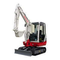
Takeuchi TB 250 Operator's Manual (10 pages)
Brand:
Takeuchi
| Category:
Compact Excavator
| Size: 0 MB
Table of Contents
Safety Alert Symbol
2
Signal Words
3
Manual Storage Compartment
4
Machine Description
5
Designated Operations
5
Break-In Period
5
Advertisement
Related Products
Takeuchi TB28FR
Takeuchi TB216
Takeuchi TB23R
Takeuchi TB228
Takeuchi TB235
Takeuchi TB20e
Takeuchi TB145
Takeuchi TB125
Takeuchi TB153 FR
Takeuchi TB014
Takeuchi Categories
Compact Excavator
Excavators
Compact Loader
Tractor
Construction Equipment
More Takeuchi Manuals
Login
Sign In
OR
Sign in with Facebook
Sign in with Google
Upload manual
Upload from disk
Upload from URL