Sign In
Upload
Manuals
Brands
TA Instruments Manuals
Measuring Instruments
AR 2000
TA Instruments AR 2000 Manuals
Manuals and User Guides for TA Instruments AR 2000. We have
1
TA Instruments AR 2000 manual available for free PDF download: Operator's Manual
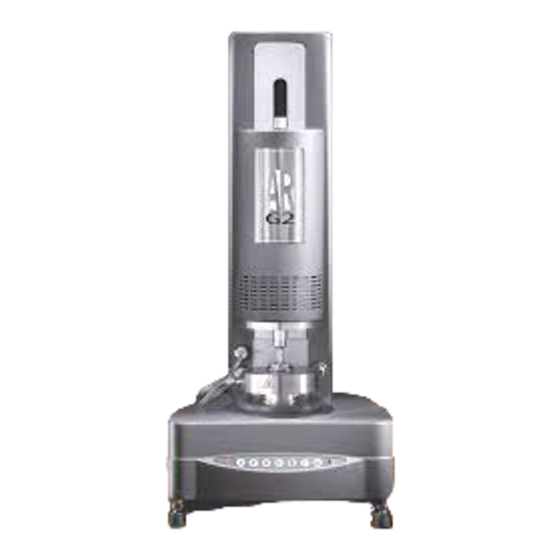
TA Instruments AR 2000 Operator's Manual (144 pages)
Rheometer Series
Brand:
TA Instruments
| Category:
Measuring Instruments
| Size: 2.97 MB
Table of Contents
Important: TA Instruments Manual Supplement
3
Table of Contents
4
Notes, Cautions, and Warnings
10
Chapter 1: Introducing the AR 2000
11
Overview
11
Warnings
11
Attention
13
Safety and EMC Conformity
15
Specifications
15
Safety
15
Emc
15
La Sûreté Et EMC Conformité
16
Spécifications
16
Sûreté
16
Emc
16
Lifting and Carrying Instructions
17
Electrical Safety
17
Liquid Nitrogen Safety
18
Handling Liquid Nitrogen
19
If a Person Is Burned by Liquid Nitrogen
19
Chemical Safety
19
Usage Instructions
20
Maintenance and Repair
20
Chapter 2: Description of the AR 2000
21
Overview
21
A Brief History of Controlled-Stress Rheometers
21
TA Instruments AR Rheometers
22
Schematics of the AR 2000 Rheometer
22
Instrument Components
23
Chapter 3: Technical Descriptions
25
Overview
25
The Air Bearing
25
Rotational Mapping
26
Auto Gapset Mechanism
27
Zeroing of the Gap
27
Closing the Gap
27
Thermal Compensation
27
Smart Swap
28
The Peltier Plate
28
Normal Force Transducer
29
Chapter 4: Technical Specifications
31
Overview
31
Specifications
31
Chapter 5: Installation and Operation
35
Overview
35
Removing the Packaging and Preparing for Installation
35
Installation Requirements
36
Connecting the System Together
37
Connecting the Rheometer to the Electronics Control Box
37
Connecting the Computerto the Electronics Control Box
37
Connecting Air and Water to the Rheometer
38
Using Smart Swap
39
Installing the Peltier Plate
39
Removing the Peltier Plate
40
Setting up the Concentric Cylinder System
41
Changing the Cup
42
Using the ETC
43
Installing the Low Temperature Accessory
46
Operating Hints
49
Controlling Cooling
49
Low Temperature System Maintenance
49
General Operating Guidelines
50
Do Not
50
Keypad Functionality
51
Levelling the Rheometer
52
Checking Your System
52
Calibrating the Rheometer
53
Shut-Down Procedure
53
Cleaning the Filter Regulator Assembly
54
Chapter 6: Measuring Systems
55
Overview
55
General Description
55
Geometry Materials
55
Stainless Steel
55
Aluminium
55
Plastic
56
Cone and Plate
56
Parallel Plate
57
Concentric Cylinders
58
Using the Stress and Shear Rate Factors
59
Choosing the Best Geometry
60
Cone and Plate/Parallel
60
Plate Systems
60
Angles
60
Diameters
60
Material
61
Preventing Solvent Evaporation
62
Preventing Slippage at Sample/Geometry Interface
62
Removing the Air-Bearing Clamp
63
Attaching a Geometry
64
Ensuring that the Sample Is Loaded Correctly
65
Chapter 7: Using the Upper Heated Plate
67
Introduction to the Upper Heated Plate
67
Attaching the Upper Heated Plate to the AR 2000
68
Installing the (Optional) Vortex Air Cooler
70
Configurations for the Cooling Water
72
Connecting the Cooling Control Unit
73
Using Circulating Fluids Other than Water
74
Connecting and Disconnecting the Geometry Holder
76
Connecting the Geometry and Holder
76
Removing the Geometry and Holder
76
Configuring the Upper Heated Plate
77
Calibration of the Upper Heated Plate
78
Clamping the Air Bearing
81
Using an Inert Gas Atmosphere
82
Using the Sample Cover
83
Chapter 8: The Pressure Cell
85
Overview
85
Specifications
86
Operating Specifications
86
Safety Specifications
86
Operational Limits
86
Pressure Cell Components
87
The Pressure Cell Cup
88
The Inlet Port
88
The Pressure Gauge Port
88
Safety Relief Port
89
Rotor Assembly
89
Magnet Assembly
90
Pressure Manifold
91
Requirements for External Pressure Source
92
Installing and Using the Pressure Cell
93
Step 1: Install High-Pressure Piping Manifold
94
Step 2: Install and Configure Pressure Cell Cup and Rotor
95
Step 3: Positioning Gap and Pressure Cell Calibrations
97
Step 4: Loading a Sample
98
Step 5: Align Manifold and Make Manifold Connections
100
Step 6: Pressurizing/Depressurizing the Cell and Running Experiments
101
Running Experiments in Self-Pressurization Mode
102
Running Experiments in External Pressurization Mode
104
Maintaining the Cell
106
Cleaning the Pressure Cell Cup
106
Cleaning the Rotor Assembly
106
Disassembling the Rotor
107
Reassembling the Rotor
108
Replacement Parts
110
Chapter 9: AR 2000 Interfacial Accessory
111
Overview
111
Specifications
112
Setting up the Interfacial Accessory
113
Calibration and Mapping
114
Zeroing the Gap
114
Mapping and Other Calibrations
114
Experimental Procedure
115
Determining each Fluid's Contribution
115
Finding the Interface Position
116
Analyzing the Results
118
Calculation of the Interfacial Contribution to the Torque
118
Interfacial Shear Stress and Shear Rate Calculation
119
Part Numbers
119
References
119
Chapter 10 Do's and Don'ts
121
Overview
121
Don't
122
Appendix A Useful Information
123
Moments of Inertia
123
Calculations for Moments of Inertia
123
Cone
123
Cylinder
124
Appendix B Symbols and Units
125
Appendix C: Geometry Form Factors
127
Cone/Plates
127
Concentric Cylinder Dimensions
127
Appendix D: LCD Display Messages
129
Power on Messages
129
Initialising
129
Bearing Overspeed
129
Bearing Pressure too Low
130
Encoder Index Not Found
130
Nf Gauge Fault
130
Nf Temp Sensor Fault
130
Operator Stop Event
130
Power Cable Fault
130
Signal Cable Fault
130
Temp Sys Element Fault
130
Temp System Environment
130
Temp System Sensor Fault
131
Other Messages
131
Appendix E: TA Instruments ETC Kits
133
ETC Torsion Rectangular Kit (543307.901)
133
ETC Parallel Plate Kit (543306.901)
133
ETC Disp. Parallel Plate Kit (543308.901)
133
Index
135
Advertisement
Advertisement
Related Products
TA Instruments ARES-G2
TA Instruments AR Series
TA Instruments AR 2000ex
TA Instruments AR-G2
TA Instruments AR 1500ex
TA Instruments DHR Series
TA Instruments DSC Q Series
TA Instruments DXF-200
TA Instruments Nano ITC 5300
TA Instruments Nano ITC 5301
TA Instruments Categories
Measuring Instruments
Laboratory Equipment
More TA Instruments Manuals
Login
Sign In
OR
Sign in with Facebook
Sign in with Google
Upload manual
Upload from disk
Upload from URL