Sign In
Upload
Manuals
Brands
Suzuki Manuals
Motorcycle
XF650 Freewind
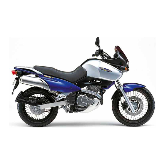
User Manuals: Suzuki XF650 Freewind Sport Motorcycle
Manuals and User Guides for Suzuki XF650 Freewind Sport Motorcycle. We have
2
Suzuki XF650 Freewind Sport Motorcycle manuals available for free PDF download: Service Manual, User Manual
Suzuki XF650 Freewind Service Manual (350 pages)
CCM 644 Engine
Brand:
Suzuki
| Category:
Motorcycle
| Size: 13 MB
Table of Contents
Index
2
Symbols
4
General Information
5
Precautions
6
Vehicle View
8
Serial Number Location
8
Fuel and Oil Recommendation
8
Brake Fluid
9
Front Fork Oil
9
Break-In Procedures
9
Information Labels
10
Specifications
12
Dimensions and Dry Mass
12
Engine Specifications
12
Transmission Specifications
12
Chassis Specifications
13
Electrical Specifications
13
Capacities
13
Country or Area - Series of Symbols
14
Periodic Maintenance
15
Periodic Maintenance Chart
16
Lubrication Points
17
Maintenance and Tune-Up Procedures
18
Valve Clearance
18
Spark Plugs
19
Carbon Deposit Check
19
Spark Plug Gap
19
Electrode's Condition
19
Air Cleaner Element
20
Idle Speed
21
Throttle Cable Play
22
Carburetor Synchronization
22
Fuel Line
23
Clutch
23
Engine Oil and Oil Filter
24
Necessary Amount of Engine Oil
24
Drive Chain
25
Brakes
27
Brake Fluid Level/Pads/Pedal Height
27
Air Bleeding the Brake Fluid Circuit
28
Tires
29
Steering
29
Front Forks
30
Rear Suspension
30
Exhaust Pipe and Muffler Bolts
30
Chassis Bolts and Nuts
31
Maintenance Illustrations
32
Compression Pressure Check
33
Compression Test Procedure
33
Oil Pressure Check/Test Procedure
34
Engine
35
Engine Components Removable with the Engine in Place
36
Engine Removal
37
Engine Reinstallation
41
Engine Disassembly
44
Engine Reassembly
52
Oil Seals
52
Balancer Shaft
53
Gearshift Mechanism
53
Crankcase
54
Cam Driven Gear
54
Gearshift Shaft
55
Neutral Position Indicator Switch
55
Oil Pump
56
Cam Chain and Primary Drive Gear/Generator and Starter Motor
56
Clutch Installation
58
Piston and Cylinder
60
Cylinder Head
61
Camshaft
62
Cylinder Head Cover
63
Cylinder Head Cover/Rocker Arm
65
Cylinder Head Cover Removal
66
Rocker Arm Removal
67
Inspection and Service
68
Cylinder Head Cover Distortion
68
Rocker Arm Shaft O.D./Rocker Arm I.D.
68
Rocker Arm Installation
68
Cylinder Head Cover Installation
69
Camshaft/Cylinder Head/Valves
71
Camshaft/Cylinder Head Removal
72
Valve Removal
73
Inspection and Service - Camshaft/Automatic De-Comp. Assembly
73
Camshaft Check
74
Camshaft Cam Wear/Journal Wear
74
Camshaft Runout
75
Cylinder Head Distortion
75
Valve Face Wear/Stem Runout
75
Valve Head Radial Runout
76
Valve Stem Deflection/Wear
76
Valve Guide Servicing
77
Valve Seat Width
77
Valve Seat Servicing
78
Valve Stem End Condition
80
Valve Spring
80
Valve Installation
81
Cylinder Head/Camshaft Installation
82
Cylinder/Piston
83
Cylinder/Piston Removal
84
Cylinder Distortion/Bore
84
Piston Diameter
84
Piston-Cylinder Clearance
84
Piston Ring-Groove Clearance
85
Piston Ring Free and Gap and Piston Ring End Gap
85
Piston/Cylinder Installation
86
Oil Ring
86
Top Ring and 3Nd Ring
86
Piston Pin and Pin Bore
86
Starter Motor/Generator Rotor/Gearshift
87
Starter Motor Removal
88
Generator Rotor Removal
88
Gearshift Shaft Removal
89
Starter Clutch Inspection
89
Starter Torque Limiter
89
Generator Rotor Installation
90
Gearshift Shaft Installation
90
Starter Motor Installation
90
Clutch Operations
91
Clutch Removal
92
Clutch Inspection and Service
93
Clutch Drive Plate
93
Clutch Driven Plate
93
Clutch Spring Free Length
93
Clutch Release Bearing
94
Clutch Release Pinion and Rack/Clutch Installation
94
Gearshift Cam/Transmission
95
Gearshift Cam/Transmission Removal
96
3Nd Drive Gear Disassemlby
96
Gearshift Cam/Transmission Inspection and Service
96
Gearshift Fork Groove Clearance
96
Transmission/Gearshift Cam Installation
97
3Rd Deiven Gear Bushing
97
Transmission Diagram
98
Balancer Shaft/Crankshaft/Crankcase
99
Balancer Shaft/Crankshaft/Crankcase Removal
100
Balancer Shaft Disassembly
100
Crankshaft Disassembly
100
Balancer Shaft/Crankshaft/Crankcase Inspection and Service
100
Conrod Deflection and Conrod Big End Side Clearance
101
Crankshaft Runout/Balancer Shaft
101
Crankshaft Assembly
102
Balancer Shaft Assembly
102
Crankcase Bearings
102
Crankcase/Crankshaft/Balancer Shaft Installation
103
Engine Lubrication System
104
Oil Filter
105
Oil Pump Removal and Disassembly
105
Oil Pump Inspection
106
Oil Nozzle and Oil Jet Removal
107
Oil Nozzle and Oil Jet Inspection/Reassembly
108
Oil Sump Filter Removal/Inspection
108
Fuel and Lubrication System
109
Fuel System
110
Fuel Valve Mechanism
111
Fuel Valve/Fuel Filter Removal
111
Fuel Valve/Fuel Filter Inspection and Cleaning
112
Fuel Tank Removal
112
Carburetor Construction/Diagram
114
Carburetor Specificatons
115
Slow System
116
Main System
117
Diaphragm and Piston Operation
118
Upper/Lower Position of Piston Valve
118
Piston Valve Lift Control System
119
Starter System
120
Float System
120
Removal
121
Disassembly
122
Pilot Screw Removal (for E-18 Model)
125
Carburetor Cleaning
126
Carburetor Inspection
127
Needle Valve Inspection
127
Float Height/Solenoid Valve Inspection
127
V.T.V. Inspection
128
Throttle Position Sensor Inspection
128
Carburetor Reassembly and Remounting
128
Throttle Position Sensor Positioning
129
Piston Valve Lift Control System/Carburetor Clamps
130
Carburetor Synchronization/Calibrating each Gauge
131
Lubrication System and Cooling System
133
Oil Pressure/Filter/Sump Filter
133
Engine Lubrication/Cylinder Head Cooling System Chart
134
Fuel and Lubrication System Diagram
135
Oil Cooler Diagram
136
Oil Cooler Removal
137
Chassis
138
Chassis Exterior Parts, Construction
139
Chassis Removal - Fairing
140
Frame Cover
142
Frame Covers and Fairing Remounting
142
Front Wheel Diagram
143
Front Wheel Removal
145
Front Wheel Inspection and Disassembly
145
Wheel Bearing
145
Front Axle
146
Wheel Rim
146
Spoke Nipple
146
Front Wheel Reassembly and Remounting
147
Brake Disc
147
Front Fork Diagram/Removal and Disassembly
149
Front Fork Inspection
152
Fork Spring
152
Inner Tube and Outer Tube
152
Front Fork Reassembly and Remounting
153
Damper Rod Ring
153
Outer Tube Metal, Oil Seal and Dust Seal
154
Damper Rod Bolt
154
Front Oil/Spring
155
Front Fork Remounting
155
Steering Diagram/Removal and Disassembly
156
Steering Inspection
160
Steering Reassembly and Remounting
161
Bearing Races
161
Stem Unit
161
Handlebars
162
Rear Wheel Diagram
163
Rear Wheel Removal
164
Wheel Bearing and Sprocket Drum Bearing
166
Rear Wheel Reassembly and Remounting
167
Rear Axle/Sprocket/Rear Sprocket Damper
167
Brake Disc/Rear Axle Nut
168
Rear Swingarm and Suspension
169
Rear Swingarm and Suspension Reassembling Information
170
Rear Swingarm and Suspension Removal
171
Rear Swingarm and Suspension Inspection and Disassemlby
173
Swingarm
173
Cushion Lever
173
Rear Swingarm and Suspension Reassembly and Remounting
174
Swingarm Bearing
174
Cushion Lever Bearing
174
Shock Absorber
174
Rear Swingarm and Suspension Final Inspection and Adjustment
175
Shock Absorber Spring Pre-Load Adjustment
175
Shock Absorber Damping Force Adjustment
175
Front Brake
176
Brake Pad Replacement
177
Brake Fluid Replacement
177
Caliper Removal and Disassembly
178
Caliper Inspection
179
Caliper Reassembly and Remounting
179
Brake Disc Inspection
180
Master Cylinder Removal and Disassembly
180
Master Cylinder Inspection
182
Master Cylinder Reassembly and Remounting
182
Rear Brake Exploded Diagram
183
Rear Brake Pad Replacement
184
Rear Brake Fluid Replacement
184
Rear Brake Caliper Removal and Disassembly
185
Rear Brake Caliper and Disc Inspection
186
Rear Brake Caliper Reassembly and Remounting
186
Rear Brake Master Cylinder Removal and Disassembly
187
Rear Brake Master Cylinder Inspection
188
Rear Brake Master Reassembly and Remounting
188
Lowering the Seat Height
189
Front Fork Exploded Diagram
190
Front Fork Removal and Disassembly
191
To Reassemble and Remount the Front Fork and Fron Wheel
193
Rear Shock Absorber
197
Rear Shock Absorber Removal and Disassembly
198
Side-Stand Exploded Diagram
199
Spring Setting Table
199
Side-Standing Removal and Installation
200
Warning Label
200
Electrical System
201
Cautions in Servicing the Electrical System
202
Connector, Coupler, Clamp, Fuse, Semi-Conductor Equipped Part
202
Battery/Connecting Battery
203
Wiring Procedure
203
Using Multi Circuit Tester
203
Location of Electrical Components
204
Charging System Description and Schematic Diagram
206
Troubleshooting: Battery Runs down Quickly
207
Battery Leak Current Inspection
208
Charging Output Inspection
208
Generator Coil Continuity Inspection
209
Generator No-Load Performance Inspection
209
Regulator/Rectifier Inspection
210
Starter System Description and Schematic Disgram
211
Side-Stand/Ignition Interlock System Description and Schematic Disgram
211
Troubleshooting: Starter Motor will Not Run
213
Starter Motor Removal and Disassembly
214
Starter Motor Inspection
214
Carbon Brush Inspection
214
Commutator/Armature Coil/Oil Seal Inspection
215
Starter Motor Reassembly
215
Starter Relay Inspection
216
Starter Relay Circuit Diagram
217
Side-Stand/Ignition Interlock System Inspection
217
Diode
217
Neutral Switch
218
Side-Stand Switch
218
Side-Stand/Ignition Interlock Relay
219
Clutch Lever Position Switch
219
Ignition System Description and Circuit Diagram
220
Troubleshooting: no Spark or Poor Spark
221
Ignition Coil Primary Peak Voltage Inspection
222
Ignition Coil - Checking with Electro Tester
223
Ignition Coil Resistance
223
Power Source Coil and Pick-Up Coil
224
Spark Plug Inspection
225
Carbon Deposit, Spark Plug Gap Check
225
Combinator Meter Removal/Disassembly
226
Combinator Meter Inspection
227
Speedometer/Speed Sensor Inspection
228
Fuel Meter Inspection
229
Fuel Level Gauge Removal/Installation
229
Fuel Level Gauge Inspection
230
Lamps
230
Headlight and Position Light Diagram
230
Headlight/Position Light Replacement
231
Tail/Brake Light, Turn Signal Light and License Plate Light Exploded Diagram
232
Tail/Brake Light Replacement
232
Turn Signal Relay
233
Turn Signal Light Replacement
233
Switches Inspection
234
Battery Specifications
235
Battery Initial Charging
235
Battery Servicing
236
Battery Recharging Operation
237
Servicing Information
238
Troubleshooting - Engine
239
Troubleshooting - Carburetor
242
Troubleshooting - Chassis
242
Troubeshooting - Brakes
243
Troubleshooting - Electrical
244
Troubleshooting - Battery
245
Wiring Diagram for Australia
246
Wiring Diagram for the Other Market
247
Wire Routing Diagrams
248
Cable Routing Diagrams
252
Carburetor and Air Cleaner Hose Routing Diagrams
254
Pair (Air Supply) System Hose Routing Diagram (for Austria and Switzerland)
255
Front Brake Hose Routing Diagrams
256
Rear Brake Hose Routing Diagram
257
Fuel Tank Water Drain Hose Routing Diagram
258
Oil Hose Routing Diagram
259
Fairing Set-Up Diagram
260
Fuel Tank Cover Set-Up Diagram
260
Protector and Heat Shield Adhering
261
Side Stand Spring Set-Up
262
Special Tools Illustrations
263
Tighterning Torque - Engine
266
Tighterning Torque - Chassis
267
Tighterning Torque for Other Bolts and Nuts Chart
268
Service Data - Valve+Guide
269
Service Data - Camshsft + Cylinder Head
270
Service Data - Cylinder + Piston + Piston Ring
270
Service Data - Conrod + Crankshaft/Oil Pump
271
Service Data - Clutch/Transmission + Drive Chain
272
Service Data - Carburetor
273
Service Data - Electrical/Wattage
274
Service Data - Brake + Wheel
275
Service Data - Suspension/Tire Pressure/Fuel + Oil
276
XF650W/UW/X/UX ('98, '99-Models)
277
XF650W/UW/X/UX ('98, '99-Models) - Specifications
278
XF650W/UW/X/UX ('98, '99-Models) Service Data - Valve+Guide
279
XF650W/UW/X/UX ('98, '99-Models) Service Data - Camshaft + Cylinder Head
280
XF650W/UW/X/UX ('98, '99-Models) Service Data - Cylinder + Piston + Piston Ring
280
XF650W/UW/X/UX ('98, '99-Models) Service Data - Conrod + Crankshaft/Oil Pump
281
XF650W/UW/X/UX ('98, '99-Models) Service Data - Clutch/Transmission + Drive Chain
282
XF650W/UW/X/UX ('98, '99-Models) Service Data - Carburetor
283
XF650W/UW/X/UX ('98, '99-Models) Service Data - Electrical/Wattage
284
XF650W/UW/X/UX ('98, '99-Models) Service Data - Brake + Wheel
285
XF650W/UW/X/UX ('98, '99-Models) Service Data - Suspension/Tire Pressure/Fuel + Oil
286
XF650W/UW/X/UX ('98, '99-Models): Carburetor and Air Cleaner Hose Routing
287
XF650W/UW/X/UX ('98, '99-Models): Oil Pump (from X-Model)
288
XF650Y (2000-Model)
289
XF650Y (2000-Model) Specifications - Dimensions and Dry Mass
291
XF650Y (2000-Model) Specifications - Engine/Transmission
291
XF650Y (2000-Model) Specifications - Chassis/Electrical/Capacities
292
XF650Y (2000-Model) Engine
293
XF650Y (2000-Model) Engine Reassembly - Clutch
294
XF650Y (2000-Model) Inspection and Service - Clutch Drive Plates/Driven Plates
298
XF650Y (2000-Model) Chassis
299
XF650Y (2000-Model) Exterior Parts Construction
300
XF650Y (2000-Model) Fairing Removal
301
XF650Y (2000-Model) Frame Cover Removal/Remounting
303
XF650Y (2000-Model) Electrical System
304
XF650Y (2000-Model) Lamps/Headlight and Position Light/Bulb Replacement
305
XF650Y (2000-Model) Position Light Removal
306
XF650Y (2000-Model) Servicing Information
307
XF650Y (2000-Model) Wiring Diagram
308
XF650Y (2000-Model) Wire Routing
309
XF650Y (2000-Model) Front Brake Hose Routing
310
XF650Y (2000-Model) Fairing Set-Up
311
XF650Y (2000-Model) Service Data - Valve + Guide
312
XF650Y (2000-Model) Service Data - Camshaft + Cylinder Head/Cylinder + Piston + Piston Ring
313
XF650Y (2000-Model) Service Data - Conrod + Crankshaft/Oil Pump
314
XF650Y (2000-Model) Service Data - Clutch/Transmission + Drive Chain
315
XF650Y (2000-Model) Service Data - Carburetor
316
XF650Y (2000-Model) Service Data - Electrical/Wattage
317
XF650Y (2000-Model) Service Data - Brake + Wheel
318
XF650Y (2000-Model) Service Data - Suspension/Tire Pressure/Fuel + Oil
319
XF650K1 ('01-Model)
320
XF650K1 ('01-Model) Specifications
321
XF650K1 ('01-Model) Service Data - Valve + Guide/Camshaft + Cylinder Head
322
XF650K1 ('01-Model) Service Data - Cylinder + Piston + Piston Ring/Conrod + Crankshaft/Oil Pump
323
XF650K1 ('01-Model) Service Data - Clutch/Transmission + Drive Chain/Carburetor
324
XF650K1 ('01-Model) Service Data - Electrical
325
XF650K1 ('01-Model) Service Data - Wattage/Brake + Wheel
326
XF650K1 ('01-Model) Service Data - Suspension/Tire Pressure/Fuel + Oil
327
WP Shock Absorber
331
WP Suspension Shock Absorber Set-Up and Adjustment
333
Spring Preload
333
Preload
334
Adjusting the Damping
334
The Ideal Setting
335
Adjustment Guidelines
335
WP Suspension Shock Absorber Maintenance
336
After each Race/Longer Period of Time
336
Workshop
336
Dismantling the Spring
337
Removing Nitrogen Pressure
338
Draining the Oil
338
Dismantling the Spindle
339
Fitting the Spindle
339
Refilling the Oil/Fitting the Spindle
340
Dismantling the CC Mechanism
341
Bleeding
341
Fitting the CC Mechanism
342
Refilling the Nitrogen
342
Checking the Shock Absorber
342
WP Suspension Shock Absorber Troubleshooting
343
MXMA Front Fork Adjustments
344
MXMA Front Fork Spring and Spring Pre-Load
345
MXMA Front Fork - Changing the Oil
346
MXMA Front Fork - Regular Maintenance/Troubleshooting
347
Advertisement
Suzuki XF650 Freewind User Manual (348 pages)
Brand:
Suzuki
| Category:
Motorcycle
| Size: 13 MB
Table of Contents
Group Index
1
Component Parts and Work to be Done
2
Symbol
3
General Information
4
Contents
4
Warning/Caution/Note
5
General Precautions
5
SUZUKI XF650V ('97 Model) Overview
7
Serial Number Location
7
Fuel and Oil Recommendation
7
Fuel
7
Brake-In Procedures
8
Brake Fluid
8
Front Fork Oil
8
Information Labels
9
RH View
9
LH View
9
Specifications
11
Country or Area
13
Periodic Maintenance
14
Periodic Maintenance Schedule
15
Periodic Maintenance Chart
15
Lubrication Points
16
Maintenance and Tune-Up Procedures
17
Valve Clearance
17
Spark Plugs
18
Carbon Deposit
18
Spark Plug Gap
18
Electrode's Condition
18
Air Cleaner Element
19
Idle Speed
20
Throttle Cable Play
21
Carburetor Synchronization
21
Fuel Line
22
Clutch
22
Engine Oil and Oil Filter
23
Necessary Amount of Engine Oil
23
Drive Chain
24
Checking
24
Adjusting
24
Cleaning and Lubricating
25
Brake Fluid Level
26
Brake Pads
26
Brake Pedal Height
26
Air Bleeding the Brake Fluid Circuit
27
Tires
28
Steering
28
Tire Tread Condition
28
Tire Pressure
28
Front Forks
29
Rear Suspension
29
Exhaust Pipe and Muffler Bolts
29
Chassis Bolts and Nuts
30
Compression Pressure Check
32
Compression Test Procedure
32
Compression Pressure Specification
32
Oil Pressure Check
33
Oil Pressure Test Procedure
33
Low Oil Pressure
33
High Oil Pressure
33
Engine
34
Engine Components Removable with the Engine in Place
35
Engine Removal
36
Engine Reinstallation
40
Engine Disassembly
43
Engine Reassembly
51
Oil Seals
51
Crankshaft
51
Balancer Shaft
52
Gearshift Mechanism
52
Crankcase
53
Cam Driven Gear
53
Gearshift Shaft
54
Neutral Position Indicator Switch
54
Oil Pump
55
Cam Chain and Primary Drive Gear/Generator and Starter Motor
55
Piston and Cylinder
59
Cylinder Head
60
Camshaft
61
Cylinder Head Cover
62
Cylinder Head Cover/Rocker Arm
64
Cylinder Head Cover Removal
65
Rocker Arm Removal
66
Inspection and Service
67
Rocker Arm Installation
67
Cylinder Head Cover Distortion
67
Rocker Arm Shaft O.D.
67
Cylinder Head Cover Installation
68
Camshaft/Cylinder Head/Valves
70
Camshaft/Cylinder Head Removal
71
Valve Removal
72
Camshaft/Automatic De-Comp. Assembly
72
Camshaft Cam Wear
73
Camshaft Journal Wear
73
Cylinder Head Distortion
74
Valve Face Wear
74
Valve Stem Runout
74
Valve Head Radial Runout
75
Valve Stem Deflection
75
Valve Stem Wear
75
Valve Guide Servicing
76
Valve Seat Width
76
Valve Seat Servicing
77
Valve Stem End Condition
79
Valve Spring
79
Valve Installation
80
Cylinder Head/Camshaft Installation
81
Cylinder/Piston
82
Cylinder/Piston Removal
83
Cylinder Distortion
83
Cylinder Bore
83
Piston-Cylinder Clearance
83
Piston Ring-Groove Clearance
84
Piston Ring Free End Gap and Piston Ring End Gap
84
Piston/Cylinder Installation
85
Piston Pin and Pin Bore
85
Oil Ring
85
Top Ring and 2Nd Ring
85
Starter Motor/Generator Rotor/Gearshift
86
Starter Motor Removal
87
Generator Rotor Removal
87
Gearshift Shaft Removal
88
Starter Clutch
88
Starter Torque Limiter
88
Generator Rotor Installation
89
Gearshift Shaft Installation
89
Starter Motor Installation
89
Clutch Removal
91
Clutch Drive Plate
92
Clutch Driven Plate
92
Clutch Spring Free Length
92
Clutch Installation
93
Clutch Release Bearing
93
Clutch Release Pinion and Rack
93
Gearshift Cam/Transmission
94
Gearshift Cam/Transmission Removal
95
Gearshift Fork Groove Clearance
95
2Nd Drive Gear Disassembly
95
Transmission/Gearshift Cam Installation
96
Balancer Shaft/Crankshaft/Crankcase
98
Balancer Shaft/Crankshaft/Crankcase Removal
99
Balancer Shaft Disassembly
99
Crankshaft Disassembly
99
Conrod Small End I.D.
99
Conrod Deflection and Conrod Big End Side Clearance
100
Crankshaft Runout
100
Crankshaft Assembly
101
Balancer Shaft Assembly
101
Crankcase Bearings
101
Crankcase/Crankshaft/Balancer Shaft Installation
102
Engine Lubrication System
103
Oil Filter
104
Removal and Disassembly
104
Inspection
105
Assembly and Installation
105
Oil Nozzle and Oil Jet Removal
106
Oil Sump Filter
107
Fuel and Lubrication System
108
Fuel System
109
Fuel Valve
110
Fuel Valve Mechanism
110
Fuel Valve/Fuel Filter Removal
110
Inspection and Cleaning
111
Fuel Tank Removal
111
Carburetor
113
Construction
113
I.D. No. Location
114
Slow System
115
Main System
116
Diaphragm and Piston Operation
117
Lower Position of Piston Valve
117
Upper Position of Piston Valve
117
Piston Valve Lift Control System
118
Starter System
119
Float System
119
Removal
120
Disassembly
121
Pilot Screw Removal
124
Carburetor Cleaning
125
Needle Valve Inspection
126
Float Height Adjustment
126
Solenoid Valve Inspection
126
V.T.V. Inspection
127
Throttle Position Sensor Inspection
127
Reassembly and Remounting
127
Throttle Position Sensor Positioning
128
Carburetor Clamps
129
Calibrating each Gauge
130
Lubrication System and Cooling System
132
Engine Lubrication/Cylinder Head Cooling System Chart
133
Oil Pan
133
Oil Cooler
135
Chassis
137
Exterior Parts Construction
138
Frame Cover
141
Remounting
141
Front Wheel
142
Wheel Bearing
144
Front Axle
145
Wheel Rim
145
Spoke Nipple
145
Brake Disc
146
Front Fork
148
Fork Spring
151
Inner Tube and Outer Tube
151
Damper Rod Ring
152
Inner Tube Metal
152
Outer Tube Metal, Oil Seal and Dust Seal
153
Damper Rod Bolt
153
Fork Oil
154
Front Fork Remounting
154
Bearing Races
160
Bearing
160
Stem Nut
160
Handlebars
161
Rear Wheel
162
Wheel Bearing and Sprocket Drum Bearing
165
Rear Axle
166
Rear Sprocket
166
Rear Sprocket Damper
166
Rear Axle Nut
167
Rear Swingarm and Suspension
168
Reassembling Information
169
Swingarm
172
Cushion Lever
172
Shock Absorber
173
Swingarm Pivot Shaft
173
Swingarm Bearing
173
Cushion Lever Bearing
173
Final Inspection and Adjustment
174
Shock Absorber Spring Pre-Load Adjustment
174
Spring Setting Table
174
Shock Absorber Damping Force Adjustment
174
Front Brake
175
Brake Pad Replacement
176
Brake Fluid Replacement
176
Caliper Removal and Disassembly
177
Caliper Inspection
178
Caliper Reassembly and Remounting
178
Brake Disc Inspection
179
Master Cylinder Removal and Disassembly
179
Master Cylinder Inspection
181
Master Cylinder Reassembly and Remounting
181
Rear Brake
182
Caliper and Disc Inspection
185
Lowering the Seat Height
188
Optional Parts Supply
188
Special Tools
188
Rear Shock Absorber
196
Side-Stand
198
Side-Stand Removal and Installation
199
Warning Label
199
Electrical System
200
Cautions in Servicing
201
Connector
201
Coupler
201
Clamp
201
Battery
202
Connecting Battery
202
Wiring Procedure
202
Using Multi Circuit Tester
202
Location of Electrical Components
203
Charging System
205
Description
205
Troubleshooting
206
Battery Leak Current Inspection
207
Charging Output Inspection
207
Generator Coil Continuity Inspection
208
Generator No-Load Performance Inspection
208
Regulator/Rectifier Inspection
209
Starter System Description
210
Side-Stand/Ignition Interlock System Description
210
Starter Motor Removal and Disassembly
213
Starter Motor Inspection
213
Carbon Brush
213
Starter Motor Reassembly
214
Commutator
214
Armature Coil Inspection
214
Oil Seal Inspection
214
Starter Relay Inspection
215
Side-Stand/Ignition Interlock System Inspection
216
Starter Relay Circuit Diagram
216
Diode
216
Neutral Switch
217
Side-Stand Switch
217
Side-Stand/Ignition Interlock Relay
218
Clutch Lever Position Switch
218
Ignition System
219
Ignition Coil Primary Peak Voltage
221
Ignition Coil (Checking with Electro Tester)
222
Ignition Coil Resistance
222
Power Source Coil and Pick-Up Coil
223
Combination Meter
225
Speedometer Inspection
227
Speed Sensor Inspection
227
Fuel Meter Inspection
228
Fuel Level Gauge Removal/Installation
228
Fuel Level Gauge Inspection
229
Lamps
229
Headlight and Position Light
229
Bulb Replacement
230
Tail/Brake Light, Turn Signal Light and License Plate Light
231
Turn Signal Relay
232
Switches
233
Battery Specifications
234
Initial Charging
234
Recharging Operation
236
Servicing Information
237
Engine Troubleshooting
238
Carburetor Troubleshooting
241
Chassis Troubleshooting
241
Brake Troubleshooting
242
Electrical Troubleshooting
243
Battery Troubleshooting
244
Wiring Diagram for Australia
245
Wiring Diagram for the Other Market
246
Wire Routing
247
Cable Routing
251
Carburetor and Air Cleaner Hose Routing
253
Pair (Air Supply) System Hose Routing
254
Front Brake Hose Routing
255
Rear Brake Hose Routing
256
Fuel Tank Water Drain Hose Routing
257
Oil Hose Routing
258
Fairing Set-Up
259
Fuel Tank Cover Set-Up
259
Protector and Heat Shield Adhering
260
Side Stand Spring Set-Up
261
Tightening Torque
265
Tightening Torque Chart
267
Service Data
268
XF650W/UW/X/UX ('98, '99-Models)
276
Oil Pump (from X-Model)
287
XF650Y (2000-Model)
288
General Specifications
290
Inspection and Service Clutch
297
Clutch Drive Plates
297
Clutch Driven Plates
297
Wiring Diagram
307
XF650K1 ('01-Model)
319
R30 Harness
328
Dual Sports Harness
329
Shock Absorber Manual
330
Set-Up & Adjustment
332
Spring Preload
332
Adjusting the Damping
333
The Ideal Setting
334
Adjustment Guidelines
334
Maintenance
335
After each Race
335
After a Longer Period of Time
335
Workshop
335
Workshop Spring
336
Dismantling the Spring
336
Draining the Oil
337
Removing Nitrogen Pressure
337
Dismantling the Spindle
338
Fitting the Spindle
338
Refilling the Oil
339
Bleeding
340
Dismantling the CC Mechanism
340
Assembly
341
Refilling the Nitrogen
341
Checking the Shock Absorber
341
Advertisement
Related Products
Suzuki freewind
Suzuki GRAND VITARA XL-7
Suzuki xl7 2006
Suzuki GRAND VITARA XL-7 2001
Suzuki Mini-Grande XP-35
Suzuki 1200 bandit
Suzuki 1980 GSX400
Suzuki 1982 GS450GA
Suzuki 1987 GSX-R150
Suzuki 1989 GS500EK
Suzuki Categories
Motorcycle
Automobile
Motorcycle Accessories
Outboard Motor
Offroad Vehicle
More Suzuki Manuals
Login
Sign In
OR
Sign in with Facebook
Sign in with Google
Upload manual
Upload from disk
Upload from URL