Sign In
Upload
Manuals
Brands
Sutter Instrument Manuals
Analytical Instruments
Lambda 721
Sutter Instrument Lambda 721 Light Source Manuals
Manuals and User Guides for Sutter Instrument Lambda 721 Light Source. We have
1
Sutter Instrument Lambda 721 Light Source manual available for free PDF download: Operation Manual
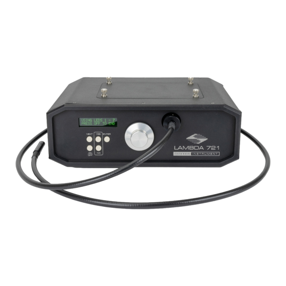
Sutter Instrument Lambda 721 Operation Manual (62 pages)
Ultra-High-Speed Optical Beam Combined 7-Channel Wavelength Switching LED Light Source System
Brand:
Sutter Instrument
| Category:
Analytical Instruments
| Size: 3 MB
Table of Contents
Disclaimer
5
Safety Warnings and Precautions
5
Electrical
5
Avoiding Electrical Shock and Fire-Related Injury
5
Electromagnetic Interference
5
Operational
5
Avoiding Physical Injury While Powered up and Emitting Light
6
Other
6
Table of Contents
7
1 Introduction
13
How to Use this Manual
13
Technical Support
13
General Description
14
Figure 1-1. Lambda 721 Indicators, Controls, and Connectors
14
Common Applications
15
Features
15
Figure 1-2. Stages of Pass-Through and Reflection from each LED Cube Light Source
15
Figure 1-3. Lambda 721 LED Spectra Options
16
2 Installation
17
Unpacking
17
Getting Started
17
Figure 2-1. Light Guide Installation
17
Figure 2-2. Rear Panel Showing Power Entry Module Receptacle and Switch
18
Configuration
19
DIP Switches
19
Figure 2-1. Rear Panel Showing Connectors for TTL Input for All 7 LED Channels, Ring Buffer Strobe Input, and USB for External Control
19
Figure 2-2. Left-Side Panel and DIP Switches
19
Table 2-1. Configuration Switches 1 - 8 Definitions
20
3 Operations
21
Controls
21
Power Switch
21
Indicators
21
LED On/Off State Indicators
21
Connectors
21
Light Beam Combiner Output
21
Figure 3-1. Locations of Individual Indicators, Controls, and Connectors on the Lambda 721 Controller Front Panel
21
Figure 3-2. Locations of Power Switch and Individual Connectors on the Lambda 721 Controller
21
Rear Panel
21
TTL Inputs (LED # 1 - 7) BNC Connectors
22
Ring Buffer BNC Connector
22
USB Device Interface Connector
22
Operation
22
Lambda 10 Mode
22
Figure 3-3. Startup Screen
22
Figure 3-4. Product and Firmware Revision Screen
22
Figure 3-5. Lambda 10 Mode Prompt
22
Control Operations
23
Mode Exit
23
TTL Mode
23
Figure 3-6. Lambda 10 Mode Prompt
23
Figure 3-7. Lambda 10 Mode Screen
23
Figure 3-8. Use TTL Mode Prompt
23
Figure 3-9. TTL Mode Start Screen
23
Control Operations
24
Mode Exit
24
Ring Buffer Mode
24
Figure 3-10. TTL Mode Running Screen
24
Figure 3-11. Use Ring Buffer Prompt
24
Figure 3-12. Run Existing Ring Buffer Prompt
24
Figure 3-13. Ring Buffer Running Screen
24
Editing the Ring Buffer
25
Running the Ring Buffer Control Operations
25
Stopping the Ring Buffer Run
25
Setup Mode
25
Figure 3-14. Edit Ring Buffer Query Screen
25
Figure 3-15. Ring Buffer Entry #1 Screen
25
Figure 3-16. Setup Mode Prompt Screen
25
Demo Mode
26
Figure 3-17. Edit Ring Buffer Query Screen
26
Figure 3-18. Demo Mode Prompt Screen
26
Figure 3-19. Enter Demo Mode Prompt Screen
26
Figure 3-20. Demo Mode Running Screen
26
4 External Control Operations
27
USB Interface
27
Virtual COM Port (VCP) Serial Port Settings
27
Handshaking
27
Table 4-1. USB-VCP Interface Serial Port Settings
27
Commands
28
Lambda 10-X Mode ('L' or 'L') Command
28
Lambda 10 Series Compatible LED Selection Commands
28
Table 4-2. Lambda 10-X Mode ('L' or 'L') Command
28
Table 4-3. Lambda 10 Series Compatible LED Selection Commands
29
TTL Mode ('T' or 'T') Command
30
Table 4-4. LED Selection Commands Using ASCII Digits
30
Table 4-5. TTL Mode ('T' or 'T') Command
30
Start Ring Buffer Run ('R' or 'R') Command
31
Return Values While Running the Ring Buffer
31
Stop TTL Mode or Ring Buffer Run ('O' or 'O') Command
31
Table 4-6. Start Ring Buffer Run ('R' or 'R') Command
31
Table 4-8. Stop TTL Mode or Ring Buffer Run ('O' or 'O') Command
31
Load Ring Buffer ('B' or 'B') Command
32
B' or 'B' Command Stop Loading Ring Buffer Entry Value
32
B' or 'B' Command Ring Buffer Entry Values
32
Table 4-9. Load Ring Buffer ('B' or 'B') Command
32
Table 4-10. 'B' or 'B' Command Stop Loading the Ring Buffer Entry Value
32
Table 4-11. 'B' or 'B' Command Ring Buffer Entry Values
32
Turn on a Discrete LED or a Group of Leds ('M' or 'M') Command
33
Table 4-12. Change the On/Off State of One or more Leds ('M' or 'M') Command
33
Set LED Power Level ('P' or 'P') Command
34
Get LED ON/OFF Status ('S' or 'S') Command
34
Get Lambda 10-3 Compatible Controller Type and Configuration Command
34
Table 4-13. Set LED Power Level ('P' or 'P') Command
34
Table 4-14. Get LED ON/OFF Status ('S' or 'S') Command
34
Get Lambda 10-3 Compatible Status Command
35
Table 4-15. Get Lambda 10-3 Compatible Controller Type and Configuration Command
35
Table 4-16. Get Lambda 10-3 Compatible Controller Type and Configuration Command
36
5 Maintenance and Reconfiguration
37
Routine Maintenance
37
Reconfiguration
37
Replacing and Installing New LED Cubes
37
Setting up the Maximum Current Level for each LED
37
Figure 5-1. LED Cube Placement
37
Figure 5-2. Setting the Maximum Current for an LED
38
Figure 5-3. Prompt for Finishing Setting LED Current Levels
38
Figure 5-4. Message to Turn off Unit and Reset DIP Switch 8 Position before Turning Unit Back
38
Figure 5-5. Lambda 10 Mode Prompt
38
Appendix A. Limited Warranty
39
Appendix B. Accessories
41
Liquid Light Guides, SMA Fiber, and Other Accessories
41
Microscope Mounting Adapters
41
LED Cubes
41
Appendix C. Fuse Replacement
43
Figure C-1. Power Entry Module and Fuse Detail
43
Appendix D. Technical Specifications
45
Table 5-1. Cable Specifications
46
Appendix E. Quick Reference
47
Manual Operation
47
Figure E-1. Lambda 721 Front Panel and Controls
47
Figure E-2. Lambda 721 Menu Navigation Diagram
47
Configuration
48
External Control
48
Figure E-3. Lambda 721 Rear Panel, Connectors, and Controls
48
Figure E-4. Lambda 721 Left-Side Panel and DIP Switches
48
Figure E-5. LED Cube Placement
48
Table E-1. Configuration Switches 1 - 8
48
Table E-2. Serial Port Settings
49
Table E-3. Lambda 721 External Control Commands
50
Table E-4. Lambda 10 Series Compatible LED Selection Commands
53
Table E-5. LED Selection Commands Using ASCII Digits
54
Table 4-7. Return Values While Running the Ring Buffer
55
Table E-6. Ring Buffer Entry Values
55
Table E-7. Return Values While Running the Ring Buffer
55
St Argument (2 Nd Byte) Values for Individual LED ON/OFF State Bit Encoding
56
Index
61
Advertisement
Advertisement
Related Products
Sutter Instrument Lambda 10-2
Sutter Instrument Lambda 10-232S
Sutter Instrument Lambda 10-250
Sutter Instrument Lambda 10-232
Sutter Instrument Lambda 10-2S
Sutter Instrument Lambda 10-3
Sutter Instrument Lambda 421
Sutter Instrument Lambda DG-4
Sutter Instrument Lambda DG-5
Sutter Instrument Lambda HPX-L5
Sutter Instrument Categories
Laboratory Equipment
Amplifier
Control Systems
Controller
Work Light
More Sutter Instrument Manuals
Login
Sign In
OR
Sign in with Facebook
Sign in with Google
Upload manual
Upload from disk
Upload from URL