Table of Contents
Advertisement
Quick Links
Lambda 721
Ultra-High-Speed Optical Beam Combined
7-Channel Wavelength Switching
LED Light Source System
With TTL & USB Interface for External Control
Operation Manual
Rev. 1.10c ((20210517)
One Digital Drive
Novato, CA 94949
Voice: 415-883-0128 Web: www.sutter.com
Fax:
415-883-0572 Email: info@sutter.com
Advertisement
Table of Contents

Subscribe to Our Youtube Channel
Summary of Contents for Sutter Instrument Lambda 721
- Page 1 Lambda 721 Ultra-High-Speed Optical Beam Combined 7-Channel Wavelength Switching LED Light Source System With TTL & USB Interface for External Control Operation Manual Rev. 1.10c ((20210517) One Digital Drive Novato, CA 94949 Voice: 415-883-0128 Web: www.sutter.com Fax: 415-883-0572 Email: info@sutter.com...
- Page 2 Copyright © 2021 Sutter Instrument Company. All Rights Reserved. LAMBDA-10 ® and SmartShutter ® are registered trademarks of Sutter Instrument Company. LAMBDA 721 OPERATION MANUAL – REV. 1.10C (20210517)
- Page 4 LAMBDA 721 OPERATION MANUAL – REV. 1.10C (20210517)
-
Page 5: Disclaimer
SAFETY WARNINGS AND PRECAUTIONS Electrical Operate the Lambda 721 using 110 – 240 VAC., 50-60 Hz line voltage. This instrument is designed for use in a laboratory environment that has low electrical noise and mechanical vibration. -
Page 6: Avoiding Physical Injury While Powered Up And Emitting Light
I) that is free from mechanical vibrations, and electrical noise and transients. DO NOT CONNECT OR DISCONNECT THE LQUID LIGHT GUIDE BETWEEN THE LAMBDA 721 AND MICROSCOPE ADAPTER (OR THE ADAPTER FROM THE MICROSCOPE) WHILE POWER IS ON. Operate this instrument only according to the instructions included in this manual. -
Page 7: Table Of Contents
3.2.1 Running the Ring Buffer Control Operations ..............13 3.2.2 Stopping the Ring Buffer Run ....................13 3.2.1 Editing the Ring Buffer ......................13 3.1 Setup Mode ............................13 3.1 Demo Mode ............................14 LAMBDA 721 OPERATION MANUAL – REV. 1.10C (20210517) - Page 8 INDEX ..............................49 TABLE OF FIGURES Figure 1-1. Lambda 721 indicators, controls, and connectors............... 2 Figure 1-2. Stages of pass-through and reflection from each LED cube light source......3 Figure 1-3. Lambda 721 LED Spectra Options..................4 Figure 2-1.
- Page 9 Figure 3-1. Locations of individual indicators, controls, and connectors on the Lambda 721 controller front panel....................... 9 Figure 3-2. Locations of power switch and individual connectors on the Lambda 721 controller rear panel........................... 9 Figure 3-3. Startup screen........................10 Figure 3-4.
- Page 10 Figure E-3. Lambda 721 rear panel, connectors, and controls............36 Figure E-4. Lambda 721 left-side panel and DIP switches..............36 Figure E-5. LED cube placement......................36 TABLE OF TABLES Table 2-1. Configuration Switches 1 – 8 definitions................8 Table 4-1.
- Page 11 Table E-9. ‘M’ Command 1 argument (2 byte) values for ON/OFF state bit encoding for all LEDs and groups........................44 LAMBDA 721 OPERATION MANUAL – REV. 1.10C (20210517)
- Page 12 (This page intentionally blank.) LAMBDA 721 OPERATION MANUAL – REV. 1.10C (20210517)
-
Page 13: Introduction
1. INTRODUCTION 1.1 Introduction The Lambda 721 is an illumination system designed for the rapid change of wavelength derived from up to seven light sources of different wavelengths combined into a single beam. The system comprises of two subsystems: controller with a built-in power supply and an array of seven LED cube and a liquid light guide or fiber couple. -
Page 14: General Description
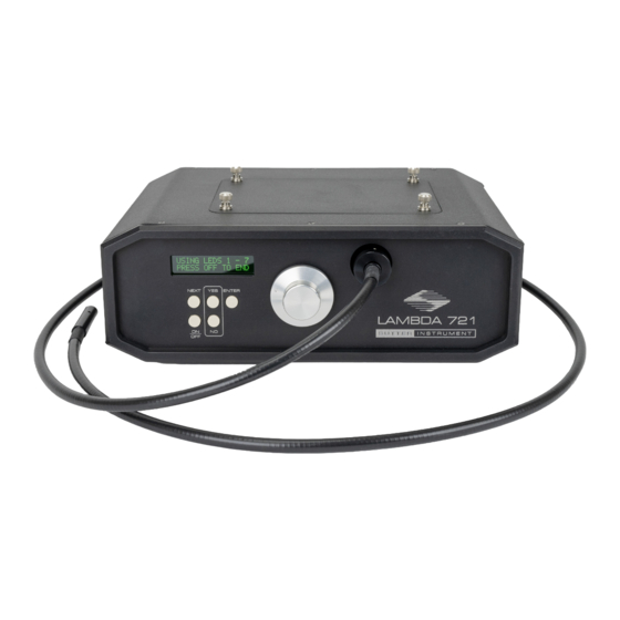
1.2 General Description Figure 1-1. Lambda 721 indicators, controls, and connectors. The Lambda 721 is a new concept for combining up to 7 separate LED cubes with different spectra into a single common output beam. The LED cubes contain the LED, collimating optics, and a filter. -
Page 15: Features
High speed wavelength selection The Lambda 721 is designed to keep the size of the beam combiner small and the optical path short and efficient. Thin-film bandpass filters, such as Semrock’s STR, reflect greater than 90% of out-of-band light. If the band pass of each light source does not overlap, it is possible to use the filters for both attenuation and reflection of the light from the other sources. -
Page 16: Figure 1-3. Lambda 721 Led Spectra Options
The Lambda optical beam combiner is designed for flexibility and expandability. Should your illumination need change over time a simple configuration change and possibly additional filters can produce an entirely different output. Figure 1-3. Lambda 721 LED Spectra Options. LAMBDA 721 OPERATION MANUAL – REV. 1.10C (20210517) -
Page 17: Installation
2. INSTALLATION 2.1 Unpacking The Lambda 721 and associated hardware comes packed in a single carton. The following is a list of the components found there. If you believe that any of these components are missing or show obvious signs of damage from shipping, please contact the factory. -
Page 18: Figure 2-2. Rear Panel Showing Power Entry Module Receptacle And Switch
5. Refer to the Operations chapter for instructions on turning on the Lambda 721, operating the controls on the front panel, and making connections to the rear panel. LAMBDA 721 OPERATION MANUAL – REV. 1.10C (20210517) -
Page 19: Configuration
2.3 Configuration The Lambda 721 is shipped with the LED cube configuration set as ordered. The unit can be operated manually and many of its features can be demonstrated without having to make any TTL input, Ring Buffer strobe, or USB connections. After first exploring the manual... -
Page 20: Table 2-1. Configuration Switches 1 - 8 Definitions
Select data (“Baud”) rate for I/O interface 57600 bps Down Reserved Off* Reserved Off* Disabled* Off** Allow setting of maximum current for each LED on power Enabled Down * Factory default setting. LAMBDA 721 OPERATION MANUAL – REV. 1.10C (20210517) -
Page 21: Operations
NEXT YES & NO ENTER Selector Dial ON/OFF Figure 3-1. Locations of individual indicators, controls, and connectors on the Lambda 721 controller front panel. TTL Inputs for Ring Buffer LEDs 1 - 7 Strobe Control USB Device Power input module: Receptacle, Receptacle fuse, &... -
Page 22: Ttl Inputs (Led # 1 - 7) Bnc Connectors
Provides the interface for controlling the Lambda 721 by computer via USB connection. 3.4 Operation The arrangement of the LED cubes in the Lambda 721 allows for up to seven light sources with differing spectral output to be combined and delivered on a common output light path. -
Page 23: Control Operations
PRESS YES OR NO Figure 3-6. Lambda 10 Mode prompt. Pressing YES places the Lambda 721 into Lambda 10 Mode, as shown in the following figure. Pressing NO, causes the next mode prompt (TTL Mode) to display, described next. USING LEDS 1 - 7 PRESS OFF TO END Figure 3-7. -
Page 24: Control Operations
PRESS YES OR NO Figure 3-11. Use Ring Buffer prompt. Pressing YES places the Lambda 721 into Ring Buffer Mode, asking if the current Ring Buffer should be run, as shown in the following figure. Pressing NO, causes the next mode prompt (Setup Mode) to display, described next. -
Page 25: Running The Ring Buffer Control Operations
Up to 100 entries are supported in the Ring Buffer. The 100 entry must contain “End RB”. Pressing OFF, exits Ring Buffer Edit mode and enters Setup mode. 3.1 Setup Mode SETUP MODE? PRESS YES OR NO Figure 3-16. Setup Mode prompt screen. LAMBDA 721 OPERATION MANUAL – REV. 1.10C (20210517) -
Page 26: Demo Mode
Pressing ENTER starts running the demo. DEMO RUNNING OFF TO STOP Figure 3-20. Demo Mode running screen. Pressing OFF stops the Demo Mode from running, returning the display to the Lambda 10 Mode prompt. LAMBDA 721 OPERATION MANUAL – REV. 1.10C (20210517) -
Page 27: External Control Operations
(www.sutter.com). The Lambda 721 requires USB CDM (Combined Driver Model) Version 2.10.00 or higher. The CDM device driver for the Lambda 721 consists of two device drivers: 1) USB device driver, and 2) VCP (Virtual COM Port) device driver. Install the USB device driver first, followed by the VCP device driver. -
Page 28: Commands
(e.g., 2 bytes into 16-bit “word” or “short”, or 4 bytes into a 32-bit “long” or “double word”). For the Lambda 721, all Ring Buffer entry values are stored as “unsigned short” (16-bit) values. A 16-bit value is transmitted and received to and from the controller as two contiguous bytes. -
Page 29: Table 4-3. Lambda 10 Series Compatible Led Selection Commands
Completion indicator NOTE: All Lambda 10 Mode commands for the Lambda 721 correspond to the Lambda 10 series filter wheel movement for Wheel A, Speed 0, Positions 1 – 7. Any other wheel-select, speed settings, and positions 8 – 9 are not supported. -
Page 30: Ttl Mode ('T' Or 'T') Command
Delay/- Bytes Offset key- char def./- Dec. Hex. Binary (Len.) pad # char. 0101 0100 0084 ‘T’ Places Lambda 721 into TTL mode. 0111 0100 0116 ‘t’ 0000 1101 <CR> Completion indicator LAMBDA 721 OPERATION MANUAL – REV. 1.10C (20210517) -
Page 31: Start Ring Buffer Run ('R' Or 'R') Command
Bytes Offset key- char def./- Dec. Hex. Binary (Len.) pad # char. 0100 1111 0079 ‘O’ Stop TTL Mode or Buffer Ring run. 0110 1111 0111 ‘o’ 0000 1101 <CR> Completion indicator LAMBDA 721 OPERATION MANUAL – REV. 1.10C (20210517) -
Page 32: Load Ring Buffer ('B' Or 'B') Command
4.3.1 Load Ring Buffer (‘B’ or ‘b’) Command This command begins the ring buffer loading sequence. Once sent, the Lambda 721 waits to receive up to 100 two-byte entry values until the Stop Loading Ring Buffer value is received. -
Page 33: Turn On A Discrete Led Or A Group Of Leds ('M' Or 'M') Command
LED value or Command 1 argument (2 byte) values for ON/OFF state bit encoding for all LEDs and groups for an LED group value. 0000 1101 <CR> Completion indicator LAMBDA 721 OPERATION MANUAL – REV. 1.10C (20210517) -
Page 34: Set Led Power Level ('P' Or 'P') Command
NOTE: The “Get Lambda 10-3 Compatible Controller Type and Configuration” command is provided to allow external-control software originally written for the Lambda 10-3 to control a Lambda 721 while identifying itself as a Lambda 10-3. All data returned is static (i.e., data LAMBDA 721 OPERATION MANUAL – REV. 1.10C (20210517) -
Page 35: Get Lambda 10-3 Compatible Status Command
Lambda 721 states). This command is functional only if DIP Switch 2 is OFF (up). Table 4-15. Get Lambda 10-3 Compatible Controller Type and Configuration Command. Tx/- Ver. Total Byte Value Alt- Ctrl- ASCII Description... -
Page 36: Table 4-16. Get Lambda 10-3 Compatible Controller Type And Configuration Command
Lambda 721 states). This command is functional only if DIP Switch 2 is OFF (up). Table 4-16. Get Lambda 10-3 Compatible Controller Type and Configuration Command. Tx/- Ver. Total Byte Value Alt- Ctrl- ASCII Description Delay/- Bytes... -
Page 37: Maintenance And Reconfiguration
5. MAINTENANCE AND RECONFIGURATION 5.1 Routine Maintenance Routine cleaning of the Lambda 721 system is required to prevent excessive dust accumulations. Wipe all exterior surfaces with a dry, soft, cotton cloth. Periodically inspect all cables ensuring that all connections are made well, and connectors are evenly seated. -
Page 38: Figure 5-2. Setting The Maximum Current For An Led
Figure 5-3. Prompt for finishing setting LED current levels. Pressing NO, returns to the “Set Max. Current” display. Pressing YES, displays a message to turn off the Lambda 721 and reset DIP Switch 8 to the OFF (UP) position. TURN OFF UNIT RESET DIP-SWITCH Figure 5-4. -
Page 39: Appendix A. Limited Warranty
Warranty work will be performed only at the factory. The cost of shipment both ways is paid for by Sutter Instrument during the first three months this warranty is in effect, after which the cost is the responsibility of the customer. - Page 40 (This page intentionally blank.) LAMBDA 721 OPERATION MANUAL – REV. 1.10C (20210517)
-
Page 41: Appendix B. Accessories
SMA fiber adapter with SMA fiber. B.2. Microscope Mounting Adapters Mounting adapters for Nikon, Zeiss, Leica and Olympus microscopes are available. Please refer to the Microscope Adapters section of Sutter Instrument’s web site (http://www.sutter.com) for further information. B.3. LED Cubes... - Page 42 721CUBE-940 LED cube with optics and filter, 940nm NOTE: For a full list of available accessories for the Lambda 721, refer to the Products section of Sutter Instrument’s web site ( http://www.sutter.com LAMBDA 721 OPERATION MANUAL – REV. 1.10C (20210517)
-
Page 43: Appendix C. Fuse Replacement
The type and rating of both fuses are as follows: 5 x 20 mm glass tube, Time Lag (IEC 60127-2, Sheet 6) T3.15A 250V (Time Lag, 3.15 Amps, 250 Volts) (Littelfuse 02193.15MXAP (219XA Series, RoHS compliant)) LAMBDA 721 OPERATION MANUAL – REV. 1.10C (20210517) - Page 44 (This page intentionally blank.) LAMBDA 721 OPERATION MANUAL – REV. 1.10C (20210517)
-
Page 45: Appendix D. Technical Specifications
5 x 20 mm glass tube, T3.15A, 250V , Time Lag (IEC 60127-2, Sheet 6) (Littelfuse 02193.15MXAP (219XA Series, RoHS compliant)) Fuse holder contains two fuses. If a fuse is blown, both fuses should be replaced. LAMBDA 721 OPERATION MANUAL – REV. 1.10C (20210517) -
Page 46: Table 5-1. Cable Specifications
3 meters (Geographical region (approx. dependent) 10 feet) ◄─A connector Dielectric Host computer’s USB │ separation of USB ”A” (Device) female “B” receptacle (full- │ circuits. Foil receptacle (full-sized) sized) B connector─► shielding. LAMBDA 721 OPERATION MANUAL – REV. 1.10C (20210517) -
Page 47: Appendix E. Quick Reference
YES & NO ENTER Selector Dial ON/OFF button: Stops/exits Lambda 10, TTL, or Ring Buffer Run/Edit modes. Figure E-1. Lambda 721 front panel and controls. SETUP Mode: Toggles state of current LED. Power-up Start. Lambda Using LEDs 1 - 7... -
Page 48: Configuration
Ring Buffer Enabled: Turns Receptacle fuse, & switch OFF before Down next strobe Figure E-3. Lambda 721 rear panel, connectors, and controls. I/O interface return of Enabled* Off* current Ring Buffer entry LED number(s) while Ring Front Rear... -
Page 49: Table E-2. Serial Port Settings
Although most command bytes I/O methodologies over which communications can be expressed as ASCII displayable/printable with the Lambda 721 can be conducted: 1). characters, the rest of a command sequence USB Direct, or 2). Serial RS-232 asynchronous must always be expressed as a sequence of via the VCP device driver. -
Page 50: Table E-3. Lambda 721 External Control Commands
LED value or Command 1 argument (2 byte) values for ON/OFF state bit encoding for all LEDs and groups for an LED group value. 0000 1101 <CR> Completion indicator LAMBDA 721 OPERATION MANUAL – REV. 1.10C (20210517) - Page 51 0100 0010 “WB-NC” 0010 1101 (Filter Wheel B is not connected) 0100 1110 0100 0011 0101 0111 0100 0011 “WC-NC” 0010 1101 (Filter Wheel C is not connected) 0100 1110 0100 0011 LAMBDA 721 OPERATION MANUAL – REV. 1.10C (20210517)
- Page 52 Status” commands are provided to allow external-control software originally written for the Lambda 10-3 to control a Lambda 721 while identifying itself as a Lambda 10-3. All data returned is static (i.e., data remains unchanged regardless of all Lambda 721 states). These two commands are functional only if DIP Switch 2 is OFF (up).
-
Page 53: Table E-4. Lambda 10 Series Compatible Led Selection Commands
Completion indicator NOTE: All Lambda 10 Mode commands for the Lambda 721 correspond to the Lambda 10 series filter wheel movement for Wheel A, Speed 0, Positions 1 – 7. Any other wheel-select, speed settings, and positions 8 – 9 are not supported. -
Page 54: Table E-5. Led Selection Commands Using Ascii Digits
(‘6’) 36 00110110 0054 Command echo 0000 1101 <CR> Completion indicator 37 00110111 0055 LED 7 On Turn LED 7 on (‘7’) 37 00110111 0055 Command echo 0000 1101 <CR> Completion indicator LAMBDA 721 OPERATION MANUAL – REV. 1.10C (20210517) -
Page 55: Table 4-7. Return Values While Running The Ring Buffer
0011 0111 LED 7 On NOTE: The return of the values shown in the table while running the ring buffer is contingent on DIP Switch 4 being set to the ON (down) position. LAMBDA 721 OPERATION MANUAL – REV. 1.10C (20210517) -
Page 56: St Argument (2 Nd Byte) Values For Individual Led On/Off State Bit Encoding
LED 5 4 3 1 On 1E 00011110 ON ON ON ON 0030 <RS> LED 5 4 3 2 On 1F 00011111 ON ON ON ON ON 0031 <US> LED 5 4 3 2 1 On LAMBDA 721 OPERATION MANUAL – REV. 1.10C (20210517) - Page 57 LED 7 4 2 On 01001010 0074 ON ON LED 7 4 2 1 On 01001011 0075 ON ON LED 7 4 3 On 01001100 0076 ON ON LED 7 4 3 1 On 01001101 0077 LAMBDA 721 OPERATION MANUAL – REV. 1.10C (20210517)
- Page 58 LED 7 6 5 4 1 On 01111001 0121 ON ON ON ON LED 7 6 5 4 2 On 01111010 0122 ON ON ON ON ON ON LED 7 6 5 4 2 1 On 01111011 0123 LAMBDA 721 OPERATION MANUAL – REV. 1.10C (20210517)
- Page 59 Byte-order reversal may be required on some platforms. two Endian formats (if Big Endian, it becomes Little Endian, Microsoft Windows, Intel-based Apple Macintosh systems and if Little Endian, it becomes then Big Endian). NOTES: LAMBDA 721 OPERATION MANUAL – REV. 1.10C (20210517)
- Page 60 NOTES: LAMBDA 721 OPERATION MANUAL – REV. 1.10C (20210517)
-
Page 61: Index
.............. 25 power switch ............9 notes dimensions............. 33 user ..............50 disclaimer ............... iii operations ..............9 electrical specs connector cable s ..............34 USB device connector ........10 external control connectors LAMBDA 721 OPERATION MANUAL – REV. 1.10C (20210517) - Page 62 Replacing and Installing New LED Cubes ..25 USB device connector........... 10 Ring Buffer BNC connector ......... 10 warranty ..............27 safety warnings ............iii weight ..............33 electrical .............. iii safety warnings & precautions NOTES LAMBDA 721 OPERATION MANUAL – REV. 1.10C (20210517)
Need help?
Do you have a question about the Lambda 721 and is the answer not in the manual?
Questions and answers