Sign In
Upload
Manuals
Brands
sunair Manuals
Amplifier
LPA-9600
sunair LPA-9600 Manuals
Manuals and User Guides for sunair LPA-9600. We have
2
sunair LPA-9600 manuals available for free PDF download: Operation And Maintenance Manual
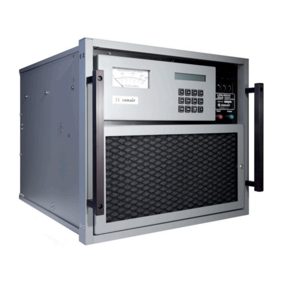
sunair LPA-9600 Operation And Maintenance Manual (136 pages)
SOLID STATE KILOWATT LINEAR POWER AMPLIFIER
Brand:
sunair
| Category:
Amplifier
| Size: 7 MB
Table of Contents
Conventions Used in this Manual
6
Safety Information
8
Table of Contents
9
Purpose of Manual
15
Purpose of Equipment
15
General Description
15
Physical Description
15
Electrical Description
15
Expected Emp Performance
16
Specifications
16
Outline and Mounting Dimensions, LPA-9600
18
LPA-9600 (Front Panel and Rear Panel)
19
Equipment Supplied
20
Equipment Required, Not Supplied
20
Optional Equipment
21
Installation
23
Unpacking and Inspection of Equipment
23
Return of Equipment to Factory
23
Installation Procedure
24
Station Layout
24
Configurations
24
Antennas and Ground Systems
24
Random Length Nonresonant Antennas
24
Broadband 50 Ohm Antennas
25
LPA-9600 with Broadband Antenna
25
LPA-9600 W/Cu-9100, 35 FT Antenna (Roof Top Installation)
26
Non-Resonant Antenna
27
KW Longwire Antenna Kit
28
External Connections
29
Primary Power Connections
29
Transceiver Connections
29
Rf Output Connections
29
Power Cable Assembly P/N 8066002297
29
Series Exciter/Transceiver to LPA-9600 Control Cable
30
Antenna Coupler Connections
31
Station Rf Ground System Connections
31
Preliminary Checks and Adjustments
31
Rack Mounting Kit Option
31
Voltage Customizing - Circuit Breaker/Auxiliary Power Supply
32
Voltage Customizing - RF/PS Module A4 (4 Each)
33
Rack Mount Slide Details
34
Shockmount Equipment Rack with Outline Dimensions and Details (Sheet 1/2)
35
Shockmount Equipment Rack with Outline Dimensions and Details (Sheet 2/2)
36
Operation
37
General
37
Function and Location of Controls and Indicators
37
Operating the Lpa-9600
37
Operation with 9000 Series Exciter/Transceiver
37
LPA-9600 Controls and Indicators
38
3 III Operation
39
Controls and Indicators Front Panel
39
Theory of Operation
41
General
41
Control Panel Module A2
41
Computer Assembly A3
42
Pc Assy Computer Mother Board A3A1
42
Peripheral Board A3A2
42
General
42
Temperature Sense Comparators
42
Gain Fault Buffer U7
43
Gain Fault Comparators U12
43
Overtemperature Buffer U3
43
VC Monitor Comparators U11
43
VC Monitor/Voltage Monitor Buffer U19
43
Voltage Monitor Comparators U13
43
Channel Multiplexer U17
44
Collector Current Meter Conditioning Circuit U16
44
Collector Voltage Meter Conditioning Circuit U14
44
Lcd Enable Inverter U6E
44
Multiplexer Switch Selector Latch U18
44
Overcurrent Detectors U15
44
Filter Fault Detector U9C, U20A
45
Forward Power Meter Conditioning Circuit U10B, U23A and Q13
45
Reflected Fault Detector U9D
45
Reflected Power Meter Conditioning Circuit U10A, U23B and Q14
45
Rf Present Detector Q4
45
Vswr Fault Detector U9B
45
Alc/Acc Control Circuit U10C, U10D, U20A, B and C, Q3 and Q12
46
Coupler Control Circuits
46
DC to Ac Converter U22
46
DC to DC Converter U21
46
General
46
Bite Bits
47
Coupler Input Detectors U6A-D, U9A
47
Coupler Interface Buffer U8
47
Lamp Driver/Relay Driver Circuit U5G
47
Output Latch U4
47
Microprocessor Board A3A3
48
General
48
Microprocessor U1
48
Address Latch U8
49
Crystal Oscillator U34
49
Divide by 2 Circuit U24B
49
Eprom U9
49
Memory Device Selector U6A, U7, U21A
49
Power Clear Circuit U2C, U4A, U4B
49
Input/Output Device Selector U10C
50
Memory I/O Device Selector U10B, U35
50
Ram-Io-Timer U13
50
Relay Drivers
50
Watchdog Circuit Q1, U2B, U3B
50
Ad0-Ad7 Buffer Circuit U2D, U2E, U6C, U20E, U20F, U32
51
Lcd Address Buffer U19
51
Lcd Enable Circuit U6B, U10A
51
U23, U24A, U26A, U27
51
Wait State Generator U4C, U4D, U4E, U5
51
Band Buffer Circuit
52
Generator
52
Interrupt Control Circuit
52
Keyboard Input Buffers U16A-U16D, U18
52
U4F, U16F, U17A
52
Voltage Present Indicators
52
Rf/Ps Module A4
53
Rf Module Control Assembly A4A1
53
48Vdc Switching Power Supply A4A2
53
Control Section
53
General
53
Input Section
53
Inverter Section
53
Current Limiting
54
Output Section
54
Overvoltage Protection
54
Power Amplifier Assembly A4A3
54
4 IV THEORY of OPERATION (Cont.)
56
Filter Module A5
56
Plug-In Filter Module A5A1 Thru A5A8
56
Plug-In Wattmeter Module A5A9
56
Mother Board Assembly A5A10
56
Output Power Combiner A6
56
Input Power Splitter Assembly A9
57
Front Panel A8
57
Rear Panel Connector Assembly A9
57
Auxiliary Power Supply A10
57
LPA-9600 Overall Block Diagram
59
Peripheral Board A3A2 Block Diagram
60
Microprocessor Board A3A3 Block Diagram
61
Power Amplifier Assembly A4A3 Block Diagram
62
Maintenance and Repair
63
Preventive Maintenance
63
Periodic Inspections
63
Corrective Maintenance
63
Test Equipment Required
63
Connectors and Cables Required
64
Primary Power Input
64
Test Conditions
64
Alignment Procedures
64
Preliminary
65
Power up
65
Keyboard
65
Power Adjustment
65
Watt Adjustment
66
Am Power
66
Vswr Adjustment
66
Fault Messages
67
Fault Isolation Procedures
68
Rf/Ps Module A4
68
Diagnostic Procedure
68
Peripheral Board A3A2
68
Filter Module A5
68
Fault, All Bands
68
Fault, One Band
69
Output Combiner A6
69
Input Splitter A7
69
Microprocessor Board A3A3
70
Disassembly Instructions
70
Fault Messages
79
RF/PS Module A4 Fault Isolation Procedures
83
Peripheral Board A3A2 Fault Isolation Procedures
85
5 V Maintenance and Repair
86
LPA-9600 Test Setup
86
Schematics and Parts Lists
87
Chassis Wiring Diagram
90
Control Panel Module A2
92
Advertisement
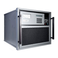
sunair LPA-9600 Operation And Maintenance Manual (138 pages)
Solid State Kilowatt Linear Power Amplifier
Brand:
sunair
| Category:
Amplifier
| Size: 80 MB
Table of Contents
Table of Contents
5
Use or Disclosure of Information from this Document Is Subject to the Restrictions
12
General Information
19
Purpose of Manual
19
Purpose of Equipment
19
General Description
19
Physical Description
19
Electrical Description
19
Specifications
20
Dimensions
21
Figure 1.5-1: LPA-9600 Outline and Mounting Dimensions
22
Figure 1.5-2: LPA-9600 Front and Rear Panels
23
Equipment Supplied
24
Equipment Required, Not Supplied
24
Table 1.6-1: LPA-9600 Equipment Supplied
24
Table 1.7-1: LPA-9600 Equipment Required, Not Supplied
24
Optional Equipment
25
Table 1.8-1: LPA-9600 Optional Equipment
25
Installation
27
General
27
Unpacking and Inspection
27
Returning Equipment to Factory
28
General Installation Information
28
Station Layout
28
Configurations
29
Antennas and Ground Systems
29
Random Length Non-Resonant Antennas
29
Broadband 50 Ohm Antennas
29
Figure 2.6-1: LPA-9600 with Broadband Antenna
30
Figure 2.6-2: LPA-9600 with CU-9150, 35-Foot Antenna (Roof Top Installation)
31
Figure 2.6-3: LPA-9600 with CU-9150, Non-Resonant Antenna
32
Figure 2.6-4: Kw Long Wire Antenna Kit
33
External Connections
34
Primary Power Connections
34
Transceiver Connections
34
RF Output Connections
34
Figure 2.7-1: Power Cable Assembly, P/N 8066002297
34
Figure 2.7-2: 9000 Series Exciter/Transceiver to LPA-9600 Control Cable
35
Antenna Coupler Connections
36
Station RF Ground System Connections
36
Preliminary Checks and Adjustments
36
Figure 2.8-1: Voltage Customizing - Circuit Breaker/Auxiliary Power Supply
37
Rack Mounting Kit Option
38
Figure 2.8-2: Voltage Customizing - RF/PS Module A4 (4 Each)
38
Figure 2.9-1: Rack Mount Slide Details
39
Table 2.9-1: LPA-9600 Rack Mounting Kit Parts List
39
Figure 2.9-2: Shockmount Equipment Rack with Outline Dimensions and Details
40
Table 2.9-2: LPA-9600 Shockmount Kit Equipment Rack Parts List, P/N 6032090892
42
Operation
43
General
43
Function and Location of Controls and Indicators
43
Figure 3.2-1: LPA-9600 Controls and Indicators
43
Table 3.2-1: Front Panel Controls and Indicators
44
Operating the LPA-9600
45
Operation with a 9000 Series Exciter/Transceiver
45
Theory of Operation
47
General
47
Control Panel Module A2
47
Computer Assembly A3
48
Use or Disclosure of Information from this Document Is Subject to the Restrictions
48
PC Assembly Computer Mother Board A3A1
48
Peripheral Board A3A2
48
Microprocessor Board A3A3
54
RF/PS Module A4
59
RF Module Control Assembly A4A1
59
VDC Switching Power Supply A4A2
59
Power Amplifier Assembly A4A3
61
Filter Module A5
62
Plug-In Filter Modules A5A1 through A5A8
62
Plug-In Wattmeter Module A5A9
62
Mother Board Assembly A5A10
63
Output Power Combiner A6
63
Input Power Splitter Assembly A7
63
Front Panel A8
63
Rear Panel Connector Assembly A9
63
Auxiliary Power Supply A10
63
Block Diagrams
64
Figure 4.11-1: LPA-9600 Overall Block Diagram
65
Figure 4.11-2: Peripheral Board A3A2 Block Diagram
66
Figure 4.11-3: Microprocessor Board A3A3 Block Diagram
67
Figure 4.11-4: Power Amplifier Assembly A4A3 Block Diagram
68
Fault Isolation, Maintenance, and Repair
69
Preventive Maintenance
69
Periodic Inspections
69
Corrective Maintenance
69
Test Equipment Required
69
Connectors and Cables Required
70
Primary Power Input
70
Test Conditions
70
Alignment Procedures
70
Preliminary
70
Power up
70
Keyboard
71
Power Adjustment
71
Watt Adjustment
72
AM Power
72
Table 5.3-1: VRMS to Watts
72
VSWR Adjustment
73
Fault Messages
73
Table 5.4-1: Fault Messages
74
Table 5.4-2: RF/PS Module A4 Fault Isolation Procedures
77
Fault Isolation Procedures
78
RF/PS Module A4
78
Peripheral Board A3A2
78
Filter Module A5
78
Output Combiner A6
79
Use or Disclosure of Information from this Document Is Subject to the Restrictions
79
Input Splitter A7
79
Microprocessor Board A3A3
79
Disassembly Instructions
79
Major Assembly Locations
80
Table 5.6-1: Disassembly Instructions
80
Figure 5.7-1: Major Assembly Locations
81
Table 5.7-1: Peripheral Board A3A2 Fault Isolation Procedures
89
Figure 5.7-2: LPA-9600 Test Setup
90
Figure 5.7-3: Audio Injection Test Cable (Used in Test Setup)
90
Schematics and Parts Lists
91
Table 5.8-1: LPA-9600 Table of Assemblies
91
Table 5.8-2: Detailed Assemblies List
93
Table 5.8-3: Detailed Assemblies List (Cont.)
94
Figure 5.8-1: Chassis Wiring Diagram
95
Figure 5.8-2: Control Panel Module A2
97
Figure 5.8-3: Computer Motherboard A3A1
98
Figure 5.8-4: Peripheral Board A3A2
101
Figure 5.8-5: Microprocessor Board A3A3
107
Figure 5.8-6: Module Control Board A4A1
113
Figure 5.8-7: 48VDC Switching Power Supply A4A2
114
Figure 5.8-8: Power Amplifier A4A3
117
Figure 5.8-9: Filter Module A5
120
Figure 5.8-10: PC Assembly, Band Filter 1, A5A1
121
Figure 5.8-11: PC Assembly, Band Filter 2, A5A2
122
Figure 5.8-12: PC Assembly, Band Filter 3, A5A3
123
Figure 5.8-13: PC Assembly, Band Filter 4, A5A4
124
Figure 5.8-14: PC Assembly, Band Filter 5, A5A5
125
Figure 5.8-15: PC Assembly, Band Filter 6, A5A6
126
Figure 5.8-16: PC Assembly, Band Filter 7, A5A7
127
Figure 5.8-17: PC Assembly, Band Filter 8, A5A8
128
Figure 5.8-18: PC Assembly, Watt Meter 9, A5A9
129
Figure 5.8-19: PC Assembly, Mother Board, A5A10
130
Figure 5.8-20: Combiner Module, A6
132
Figure 5.8-21: Splitter Module, A7
133
Figure 5.8-22: PC Assembly, Rear Panel Connector, A9
134
Figure 5.8-23: PC Assembly, Rear Panel Connector, A9
135
Figure 5.8-24: Auxiliary Power Supply, A10
136
Advertisement
Related Products
sunair Categories
Transceiver
Amplifier
Remote Control
Heater
Fan
More sunair Manuals
Login
Sign In
OR
Sign in with Facebook
Sign in with Google
Upload manual
Upload from disk
Upload from URL