
Related Manuals for sunair LPA-9600

Summary of Contents for sunair LPA-9600
- Page 1 TM-8105000504 SOLID STATE KILOWATT LINEAR POWER AMPLIFIER LPA-9600 OPERATION AND MAINTENANCE MANUAL SUNAIR 3005 SW Third Avenue, Ft. Lauderdale, FL 33315-3312...
- Page 2 No part of this publication may be reproduced, stored in a retrieval system, or transmitted in any form or by any means, electronic, mechanical, photocopying, recording, or otherwise, without the written prior written permission of Sunair Electronics Inc. Printed in the United States.
- Page 3 ABILITY OR FITNESS FOR A PARTICULAR PURPOSE. The obligation and responsibility of Sunair shall be limited to that expressly provided herein and Sunair shall not be liable for consequential or other damage or expense whatsoever therefore or by any reason thereof.
- Page 4 SUNAIR LPA-9600 SUNAIR LPA-9600 SOLID STATE KILOWATT LINEAR POWER AMPLIFIER OPERATION MAINTENANCE MANUAL SECOND EDITION AUGUST 29, 2005...
- Page 5 3005 S.W. Third Avenue Ft. Lauderdale, FL 33315-3389 U.S.A. Telephone: (954) 525-1505 Fax: (954) 765-1322 Email: techsupport@sunairhf.com TRAINING: Sunair offers training programs of varying lengths covering operation, service, and maintenance of all Sunair manufactured equipment. For details please contact the Product Service Department...
-
Page 6: Conventions Used In This Manual
SUNAIR LPA-9600 Conventions Used in this Manual ¢ Button names, names of screens and key names are printed in bold. ¢ Notes: provide information to help you accomplish tasks efficiently or to avoid problems. ¢ Mouse clicks: Unless otherwise specified, the left mouse button is used for all mouse actions. - Page 7 SUNAIR LPA-9600 TABLE of STANDARD ABBREVIATIONS ADDR Address Level Automatic Gain Control Manual Automatic Level Control M CH Manual Channel Amplitude Modulation Medium Amplitude Modulation Equivalent Megahertz AMP/AMPL Amplifier Microphone Automatic Request MIL-STD Military Standard Audio Manual AUTO Automatic Millisecond...
-
Page 8: Safety Information
SUNAIR LPA-9600 SAFETY INFORMATION The following safety information is not necessarily related to a specific procedure in this particular document. However, the information should be reviewed, understood and applied in all phases of operation and maintenance before operating the equipment described here. -
Page 9: Table Of Contents
RF OUTPUT CONNECTIONS 2.6.4 ANTENNA COUPLER CONNECTIONS 2.6.5 STATION RF GROUND SYSTEM CONNECTIONS PRELIMINARY CHECKS AND ADJUSTMENTS RACK MOUNTING KIT OPTION OPERATION GENERAL FUNCTION AND LOCATION OF CONTROLS AND INDICATORS OPERATING THE LPA-9600 3.3.1 OPERATION WITH 9000 SERIES EXCITER/ TRANSCEIVER... - Page 10 SUNAIR LPA-9600 TABLE of CONTENTS (Cont.) Section Page THEORY OF OPERATION GENERAL CONTROL PANEL MODULE A2 COMPUTER ASSEMBLY A3 4.3.1 PC ASSY COMPUTER MOTHER BOARD A3A1 4.3.2 PERIPHERAL BOARD A3A2 4.3.2.1 GENERAL 4.3.2.2 TEMPERATURE SENSE COMPARATORS U1,U2 4.3.2.3 OVERTEMPERATURE BUFFER U3 4.3.2.4...
- Page 11 SUNAIR LPA-9600 TABLE of CONTENTS (Cont.) Section Page THEORY OF OPERATION (Cont.) 4.3.3 MICROPROCESSOR BOARD A3A3 4.3.3.1 GENERAL 4.3.3.2 MICROPROCESSOR U1 4.3.3.3 ADDRESS LATCH U8 4.3.3.4 EPROM U9 4.3.3.5 POWER CLEAR CIRCUIT U2C, U4A, U4B 4.3.3.6 CRYSTAL OSCILLATOR U34 4.3.3.7 MEMORY DEVICE SELECTOR U6A, U7, U21A 4.3.3.8...
- Page 12 SUNAIR LPA-9600 TABLE of CONTENTS (Cont.) Section Page THEORY OF OPERATION (Cont.) FILTER MODULE A5 4-16 4.5.1 PLUG-IN FILTER MODULE A5A1 THRU A5A8 4-16 4.5.2 PLUG-IN WATTMETER MODULE A5A9 4-16 4.5.3 MOTHER BOARD ASSEMBLY A5A10 4-16 OUTPUT POWER COMBINER A6...
- Page 13 Outline and Mounting Dimensions, LPA-9600 LPA-9600 (Front Panel and Rear Panel) INSTALLATION LPA-9600 with Broadband Antenna LPA-9600 w/CU-9100, 35 FT Antenna (Roof Top Installation) 2-4 Non-Resonant Antenna KW Longwire Antenna Kit Power Cable Assembly P/N 8066002297 9000 Series Exciter/Transceiver to LPA-9600 Control Cable...
- Page 14 LISTING of TABLES Section Description Page OPERATION Controls and Indicators Front Panel MAINTENANCE AND REPAIR VRMS to Watts Fault Messages 5-17 RF/PS Module A4 Fault Isolation Procedures 5-21 Peripheral Board A3A2 Fault Isolation Procedures 5-23 LPA-9600 Table of Assemblies 5-25...
-
Page 15: Purpose Of Manual
1.1.1 PURPOSE OF EQUIPMENT The purpose of the LPA-9600 is to amplify the low level RF output of a separate exciter to produce 1.0 kW peak envelope power (PEP) or average power. The LPA-9600 is microprocessor controlled and operates in the frequency range of 1.6 to 30 MHz. -
Page 16: Expected Emp Performance
1.2.2.1 EXPECTED EMP PERFORMANCE The LPA-9600 is designed with an EMP environment in mind. All control and power lines into and out of the LPA-9600 are filtered. This filtering on the standard unit is adequate for a mild EMP. But for full EMP hardening, the optional EMP filter, which replaces the existing filter, is required. - Page 17 SUNAIR LPA-9600 SPURIOUS: 80 dB below PEP. BAND CHANGE TIME: 10 ms maximum. TUNING TIME: 0 seconds without coupler. With an Automatic Antenna Coupler, tuning time dependent on coupler type. TEMPERATURE RANGE: Operating -30 º C to +65 º C, Storage: -40 º C to +85 º C.
-
Page 18: Outline And Mounting Dimensions, Lpa-9600
SUNAIR LPA-9600 Figure 1.1 Outline and Mounting Dimensions, LPA-9600. -
Page 19: Lpa-9600 (Front Panel And Rear Panel)
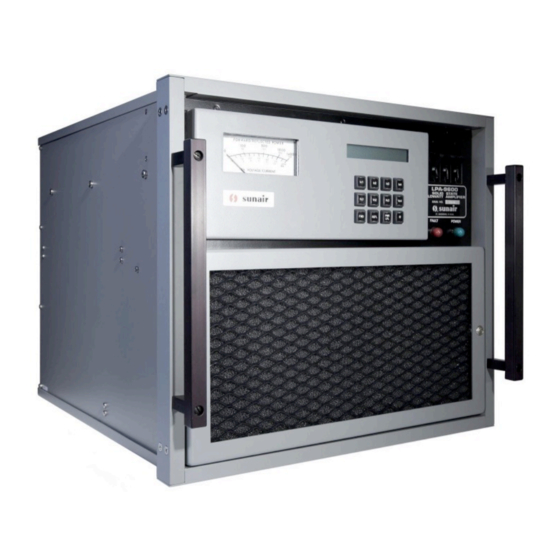
SUNAIR LPA-9600 J2 RF Output J1 RF Output J3 AC Power J4 Antenna Coupler Ground Figure 1.2 LPA-9600 (Front Panel and Rear Panel). -
Page 20: Equipment Supplied
SUNAIR LPA-9600 EQUIPMENT SUPPLIED SUNAIR PART NUMBER LPA-9600, 1 kW Linear Solid State Power Amplifier 8105000059 Gray 8105000091 Green Power Cable Assembly (10 feet) 8066002297 Operation and Maintenance Manual 8105000509 Connector Kit 8066000294 Consisting of: 2 EA Bushing, Telescoping, .56 ID 0700550054 2 EA Bushing, Telescoping, .62 ID... -
Page 21: Optional Equipment
8105900190 Depot Spares Kit 8066900091 Field Module Kit 8105905795 CU-9150 Digital Automatic 1kW Antenna Coupler 8120000056 Gray LPA-9600 to CU-9150 Control Cable Assembly 8092500096 Customer specifies length Rack Mounting Kit 8066004257 Gray Wired Rack 6032091058 Gray Shockmount Kit, Equipment Rack... - Page 22 SUNAIR LPA-9600 THIS PAGE INTENTIONALLY LEFT BLANK...
-
Page 23: Installation
INSTALLATION UNPACKING AND INSPECTION OF EQUIPMENT The LPA-9600 1 kW Linear Solid State Power Amplifier is packed in a box using double wall construction. The packing material should be removed carefully and the contents inspected for physical damage. Any claims for shipping damage must be filed promptly with the transportation company. If it is found necessary to file such a claim, retain all packing material. -
Page 24: Installation Procedure
90 pounds. Allow free circulation of air around the cabinet, and at least six inches air space between the back of the unit and any wall or partition. The companion transceiver may be placed on top of the LPA-9600 for voice or CW modes of communications. -
Page 25: Broadband 50 Ohm Antennas
50 ohm output impedance over the rated band of frequencies, an antenna coupler is not required. Some common types of broadband antenna are the Discone and Log-Periodic. Figure 2.1 is an example of a system configuration utilizing a broadband antenna. Figure 2.1 LPA-9600 With Broadband Antenna. -
Page 26: Lpa-9600 W/Cu-9100, 35 Ft Antenna (Roof Top Installation)
SUNAIR LPA-9600 Figure 2.2 LPA-9600 W/CU-9100, 35 Ft Antenna (Roof Top Installation). -
Page 27: Non-Resonant Antenna
SUNAIR LPA-9600 Figure 2.3 Non-Resonant Antenna. -
Page 28: Kw Longwire Antenna Kit
SUNAIR LPA-9600 Figure 2.4 kW Longwire Antenna Kit. -
Page 29: External Connections
EXTERNAL CONNECTIONS 2.6.1 PRIMARY POWER CONNECTIONS The LPA-9600 requires a primary power source that can provide up to 3.5 kVA (115 or 230 VAC). Whenever possible, the primary power source should be connected to the amplifier through a double-pole, 30 ampere capacity, manual disconnect switch (60 ampere if primary source is 115 VAC). -
Page 30: Series Exciter/Transceiver To Lpa-9600 Control Cable
CHANNEL 2 KW POWER ON KW POWER DETECT 2 BAND 0 SELECT BAND 6 SELECT BAND 2 SELECT BAND 4 SELECT GROUND (2 WIRES) CHANNEL 2 KW FORWARD POWER +28VDC (2 WIRES) Figure 2.6 9000 Series Exciter/Transceiver To LPA-9600 Control Cable. -
Page 31: Antenna Coupler Connections
400w/141 VRMS out. d) Set LPA-9600 to 500W. Adjust A3A2R43 for 200w/100 VRMS out. RACK MOUNTING KIT OPTION An optional slide rack mounting kit is available to facilitate installation of the LPA-9600 in standard E.I.A. equipment racks. See Figures 2.9 and 2.10. -
Page 32: Voltage Customizing - Circuit Breaker/Auxiliary Power Supply
SUNAIR LPA-9600 Figure 2.7 Voltage Customizing - Circuit Breaker/Auxiliary Power Supply. 2-10... -
Page 33: Voltage Customizing - Rf/Ps Module A4 (4 Each)
SUNAIR LPA-9600 Figure 2.8 Voltage Customizing - RF/PS Module A4 (4 Each). 2-11... -
Page 34: Rack Mount Slide Details
SUNAIR LPA-9600 RACK MOUNTING KIT LPA-9600 SUNAIR P/N 80660042XX SUNAIR P/N DESCRIPTION 80660042XX Rack Mounting Kit 50660043XX Bracket, Rack Mounting 6032041204 Chassis Slide 0538750006 Nut, Clip 10-32 0538870001 Screw, Ornamental 10-32 x 1/2 L 1002860032 Shim, Plate LPA/PS Figure 2.9 Rack Mount Slide Details. -
Page 35: Shockmount Equipment Rack With Outline Dimensions And Details (Sheet 1/2)
SUNAIR LPA-9600 Figure 2.10.1 Shockmount Equipment Rack With Outline Dimensions And Details (Sheet 1/2). 2-13... -
Page 36: Shockmount Equipment Rack With Outline Dimensions And Details (Sheet 2/2)
SUNAIR LPA-9600 SHOCKMOUNT KIT EQUIPMENT RACK SUNAIR P/N 6032090892 ITEM NO SUNAIR P/N DESCRIPTION 0501650008 Washer, Split 3/8 0501700005 Nut, Hex 3/8-16 X 9/16 AF 0542880644 Rod, Thd 3/8-16 X 4 Lg 0841810001 Isolator, Shock/Vib. 50-80 Lbs 1001280016 Isolator, Shock/Vib. 100-155 Lbs 1001290003 Bolt, Hex 5/8-11, 1½1/2 Lg... -
Page 37: Operation
1. Without an automatic antenna coupler, ‘kW SYSTEM OPERATIONAL’ is displayed and system is ready to operate. If instead the FAULT lamp on the LPA-9600 is steady, this indicates a fault in the LPA- 9600. Reset the LPA-9600 by turning the transceiver/exciter off, wait 30 seconds, then turn back on; or at the LPA-9600 turn circuit breaker OFF then ON;... -
Page 38: Lpa-9600 Controls And Indicators
SUNAIR LPA-9600 1. If after tune attempt, FAULT lamp on LPA-9600 is flashing, this indicates a fault in the coupler, antenna or feedline. Attempt retuning. If FAULT does not clear, see Section V of this manual and the 9000 Series or coupler manual. -
Page 39: Controls And Indicators Front Panel
Circuit Breaker, A8CB1 Applies primary power to the LPA-9600. FAULT Lamp, A8DS2 A red fault lamp which, when steady, indicates a fault in the LPA-9600. A flashing fault lamp indicates a fault external to the LPA-9600. POWER Lamp, A8DS1 A green lamp which indicates that primary power has been applied to the LPA-9600. - Page 40 SUNAIR LPA-9600 THIS PAGE INTENTIONALLY LEFT BLANK.
-
Page 41: Theory Of Operation
Computer Mother Board A3A1. The PWR LVL key is used to select the desired operating power level of the LPA-9600. The * key is used to scroll through multiple fault indications. The meter is used to display any of the four collector currents, four collector voltages, and either... -
Page 42: Computer Assembly A3
The Peripheral Board is responsible for the following functions required for proper operation of the LPA-9600: The signal BYPASS which causes the LPA-9600 to be bypassed in the event of a fault which in turn inhibits it from producing its power output. -
Page 43: Overtemperature Buffer U3
The signal VSWR FAULT is also monitored by A3A3U1 thru U7. If this signal goes high, A3A3U1 will reduce the power produced by the LPA-9600 from 1000 watts to 500 watts. If VSWR FAULT is still high, A3A3U1 will place LPA-9600 in BYPASS, protecting it from the excessive VSWR. -
Page 44: Collector Voltage Meter Conditioning Circuit U14
SUNAIR LPA-9600 4.3.2.9 COLLECTOR VOLTAGE METER CONDITIONING CIRCUIT U14 U14 functions as four distinct identical stages. U14A conditions the +48V from PA #1 for display on the meter, U14C conditions the +48V for PA #2, U14B conditions the +48V for the PA #3, and U14D conditions the +48V for PA #4. -
Page 45: Vswr Fault Detector U9B
LPA-9600. A3A3U1 monitors the output of U9C and if it goes high for longer than 50 ms, then A3A3U1 causes the LPA-9600 to go to BYPASS by shutting down the power amplifier assemblies, preventing them from damaging the filter module. -
Page 46: Alc/Acc Control Circuit U10C, U10D, U20A, B And C, Q3 And Q12
+28 VOLT TUNE ENABLE. When the LPA-9600 detects this signal, it immediately selects BYPASS operation so that the power being sent through the LPA-9600 to the CU-9100 is the power from the transceiver. The LPA-9600 monitors signals READY and FAULT from the CU-9100. These signals indicate the status of the CU-9100. -
Page 47: Coupler Input Detectors U6A-D, U9A
VOLT TUNE ENABLE arrives at U9A as a high anytime the CU-9100 wishes to tune. The signal called READY when low, indicates to the LPA-9600 at the end of the tune cycle that the CU-9100 has tuned properly. COUPLER PRESENT is used by A3A3U1 to detect if a CU-9100 coupler is attached. -
Page 48: Microprocessor Board A3A3
Refer to Figures 4.3 and 5.8. The Microprocessor Board A3A3 produces three major functions in the LPA-9600. The first function is the interfacing of the Keyboard to the meter. The second function is the driving of the LCD Display providing it with intelligent information. -
Page 49: Address Latch U8
The Power Clear Circuit is necessary to initialize Microprocessor U1 when power is first applied to the LPA- 9600. The circuit provides a low on pin 36 of U1 for a time after the voltage is applied to the LPA-9600. This holds U1 reset until transient conditions have passed. -
Page 50: Ram-Io-Timer U13
PA assemblies’ drive capability, Overtemp Command to increase the speed of the blower fans 1 kW, ALC/ACC to tell U1 whether to operate the LPA-9600 at 1000 or 500 watts, and the Bite Bit 2 which allows U1 to self-test various ports on the Microprocessor Board. Port C (PC0-PC5) outputs sequential lows on Rows 1-3 to the Keyboard Assembly, in conjunction with U1 reading the four columns to determine which key is being depressed. -
Page 51: Ad0-Ad7 Buffer Circuit U2D, U2E, U6C, U20E, U20F, U32
The LPA-9600 will continue to operate at 500 watts if only one power amplifier module is affected, but will go to BYPASS if more than one fails. -
Page 52: Band Buffer Circuit
The purpose of the Band Buffer Circuit is to provide a means by which Microprocessor U1 can determine which filter band has been selected in the transceiver driving the LPA-9600. When a band change occurs, U29 of the Interrupt Control Circuit will detect it and inform U1 that a band change has occurred. The band information is read on bus lines AD0 thru AD7 via U33. -
Page 53: Rf/Ps Module A4
SUNAIR LPA-9600 RF/PS MODULE A4 4.4.1 RF MODULE CONTROL ASSEMBLY A4A1 Refer to Figure 5.9. This assembly contains the bias voltage regulators for each of the two pairs of amplifier transistors in a single rf module. The AC power relay, which is energized by the microprocessor circuitry to control input to the module’s main power supply, is also a part of this module. -
Page 54: Output Section
Refer to Figures 4.4 and 5.11. The four Power Amplifier Assemblies A4A3 contain the solid state power amplifiers which produce the approximate 13 dB power gain of the LPA-9600. Refer to Figure 4.4 for the block diagram of one PA Assembly. - Page 55 SUNAIR LPA-9600 Notice that the amplifier circuits above and below the splitter and combiner are identical. Therefore, the description of the upper amplifier (Q2-Q3) will apply equally to the lower amplifier (Q4-Q5). The Input Splitter T1 is a hybrid transformer circuit which splits the 50 ohm module input into two 100 ohm outputs to drive the two push-pull amplifiers.
-
Page 56: Filter Module A5
SUNAIR LPA-9600 FILTER MODULE A5 Refer to Figure 5.12. The Filter Module consists of a fan cooled shielded enclosure, a mother board, eight plug-in filter assemblies, and a plug-in wattmeter assembly. 4.5.1 PLUG-IN FILTER MODULES A5A1 THRU A5A8 The band filters consist of three sections each and cover a useful frequency span of one-half octave maximum. -
Page 57: Input Power Splitter Assembly A9
4.3.2.5, if a module is lost, the amplifier automatically resets itself to an output level of 500 watts and continues to operate. The Output Power Combiner is located on the rear screen panel of the amplifier in the cooling airstream to transfer the dissipated power into the air and out of the LPA-9600. NOTE: You can not physically leave an RF/PS module out of the LPA-9600 and have the LPA-9600 operate. - Page 58 SUNAIR LPA-9600 THIS PAGE INTENTIONALLY LEFT BLANK. 4-18...
-
Page 59: Lpa-9600 Overall Block Diagram
SUNAIR LPA-9600 Figure 4.1 LPA-9600 Overall Block Diagram. 4-19... -
Page 60: Peripheral Board A3A2 Block Diagram
SUNAIR LPA-9600 Figure 4.2 Peripheral Board A3A2 Block Diagram. 4-20... -
Page 61: Microprocessor Board A3A3 Block Diagram
SUNAIR LPA-9600 Figure 4.3 Microprocessor Board A3A3 Block Diagram. 4-21... -
Page 62: Power Amplifier Assembly A4A3 Block Diagram
SUNAIR LPA-9600 Figure 4.4 Power Amplifier Assembly A4A3 Block Diagram. 4-22... -
Page 63: Maintenance And Repair
5.1.1 PERIODIC INSPECTIONS The LPA-9600 design calls for periodic cleaning of the air filter on the front panel asembly. Remove the air filter and clean by vacuuming or forced air. The air filter should be periodically cleaned with soap and fresh water (air filter must be completely dry before reinstallation). -
Page 64: Connectors And Cables Required
Set up LPA-9600 and required test equipment as shown in Figure 5.2. ALIGNMENT PROCEDURES The LPA-9600 is tested and aligned at the factory before shipment. The following alignment procedures should be used only by a competent technician after repair has been accomplished to the unit. If the LPA- 9600 is to be utilized with an exciter other than the one it was originally aligned to, it may be necessary to reset the power levels. -
Page 65: Preliminary
Set circuit breaker on LPA-9600 to ON. b) Turn ON 9000 Series Exciter/Transceiver. c) The green POWER lamp on the LPA-9600 front panel should illuminate. The three power supply LED’s on Microprocessor Board A3A3 should illuminate. d) On Peripheral Board A3A2 adjust R164 until the LCD Assembly A2A2 has its best contrast. The display should read: ‘KW SYSTEM OPERATIONAL METER: FWD PWR LVL: 1 KW ’... -
Page 66: Watt Adjustment
SUNAIR LPA-9600 b) While holding the CW KEY down, adjust R61 on the Peripheral Board A3A2 until the LPA-9600 panel meter indicates 1000 watts. On the keyboard depress the REFLD key, which causes the front panel meter to indicate reflected power. On the RF Wattmeter Assembly A5A9 in the Filter Module A5, adjust C62 for minimum indication on the panel meter. -
Page 67: Fault Messages
1012.500 FAULT MESSAGES Failures in the LPA-9600 cause fault messages to be displayed on the LCD Display A2A2. These messages direct attention to the areas in which failures have occurred. If more than one fault occurs, the message ‘Fault: MULTIPLE..PRESS *’ will be displayed. When this happens, depress the asterisk (*) pushbutton on the keyboard to display the fault messages. -
Page 68: Fault Isolation Procedures
Power Supply A4A2, and the Power Amplifier Assembly A4A3. The RF/PS Module may be removed as a whole and bench tested, or tests may be performed in the LPA-9600 provided the faults do not activate the LPA-9600 protection circuits. If the RF/PS Module is removed for testing, forced air cooling of the Power Amplifier and +48 VDC Power Supply MUST be provided. -
Page 69: Fault, One Band
SUNAIR LPA-9600 If no continuity exists, check circuits and coax between A5A10E21A and A5A10J22 pin T, U, 16 and 17 and connection between A5J3 and A5A10E9. g) If continuity exists, check for short circuit from antenna connection to ground. h) If all measurements fail to indicate a defect, turn power off, and remove RF Wattmeter Assembly A5A9 and inspect for burned or discolored components. -
Page 70: Microprocessor Board A3A3
Repair of this board must be accomplished at depot or factory level. NOTE: Prior to performing step 5.6, disconnect the LPA-9600 from all cabling and connections. DISASSEMBLY INSTRUCTIONS a) TOP COVER: Loosen 2 zeus screws. - Page 71 SUNAIR LPA-9600 Control Panel Module A2 Front Panel with Control Panel Module A2 and Filter Module Removed. Figure 5.1 Major Assembly Locations (Sheet 1/8).
- Page 72 SUNAIR LPA-9600 Top Covers Removed with Peripheral Board, Sunair P/N 8066082096. Figure 5.1 Major Assembly Locations (Sheet 2/8). 5-10...
- Page 73 SUNAIR LPA-9600 Top Covers Removed with Peripheral Board, Sunair P/N 8066082096. Figure 5.1 Major Assembly Locations (Sheet 3/8). 5-11...
- Page 74 SUNAIR LPA-9600 Top View with A3A2, A3A3, A5, Removed. Figure 5.1 Major Assembly Locations (Sheet 4/8). 5-12...
- Page 75 SUNAIR LPA-9600 Top Veiw with A3A2, A3A3, A5 Removed and A4#3 Pulled Out. Figure 5.1 Major Assembly Locations (Sheet 5/8). 5-13...
- Page 76 SUNAIR LPA-9600 Top View with A3A2, A3A3, A5, A4 (4 each) Removed. Figure 5.1 Major Assembly Locations (Sheet 6/8). 5-14...
- Page 77 SUNAIR LPA-9600 Bottom Cover Removed. Figure 5.1 Major Assembly Locations (Sheet 7/8). 5-15...
- Page 78 SUNAIR LPA-9600 RF/PS Module A4. Figure 5.1 Major Assembly Locations (Sheet 8/8). 5-16...
-
Page 79: Fault Messages
‘Fault: VC#X LOW’ This indicates that the output voltage from this +48V Power Supply A4A2 is low or missing. a) Remove LPA-9600 bottom cover and disconnect +48 volts input from the indicated A4 Module. b) Reset LPA-9600 controls and observe LCD display. - Page 80 This indicates that the antenna coupler failed to tune. Reset LPA-9600 and attempt retuning. If fault is repeated, refer to antenna coupler manual. ‘Fault: COUPLER UNTUNED’ This message appears when the LPA-9600 is turned on, if an antenna coupler is connected to the LPA-9600. Initiate an antenna coupler tune cycle. ‘Fault: IC#X HIGH’...
- Page 81 This message appears in conjunction with the multiple fault message and indicates that more than one filter band is being selected by the transceiver/exciter. a) Check control cable between transceiver/exciter and LPA-9600 for opens or shorts. b) Refer to transceiver/exciter manual.
- Page 82 SUNAIR LPA-9600 16. ‘Fault: 5 VOLT SUPPLY HI’ This message indicates that the +5 volts is too high. a) Measure +5 Volt Power Supply A10U2 output. b) If output voltage is high, replace 5 Volt regulator. c) If output voltage is normal, follow Peripheral Board A3A2 fault isolation procedure, paragraph 5.5.2.
-
Page 83: Rf/Ps Module A4 Fault Isolation Procedures
SUNAIR LPA-9600 Table 5.3 RF/PS Module A4 Fault Isolation Procedures. STEP NORMAL INDICATION FAILURE PROCEDURE 1. Remove + 48VDC connection from P1 of A4A3. 2. Connect multimeter to read current between +48V supply and A4A3P1. 3. Ground A4A1J3 pin 4. - Page 84 SUNAIR LPA-9600 Table 5.3 RF/PS Module A4 Fault Isolation Procedures (Cont...). STEP NORMAL INDICATION FAILURE PROCEDURE 8. Remove ground from A4A1J3 pin 4 and reconnect P1 to +48V Power Supply A4A2. 9. Connect a source of RF excitation 1.6 to 30 MHz at 0 to 20 watts through a thru-line wattmeter to A4A3J1.
-
Page 85: Peripheral Board A3A2 Fault Isolation Procedures
SUNAIR LPA-9600 Table 5.4 Peripheral Board A3A2 Fault Isolation Procedures. NOTE: The LPA-9600 has been designed to work with the CU-9100 Digital Antenna Coupler. SYMPTOM PROCEDURE ALC and ACC Inop. a. Check FWD Power input to A3A2R32 and A3A2R42. b. Check A3A2CR4. -
Page 86: Lpa-9600 Test Setup
With CU-9150 50 Ω LOAD WATT WATT HP410C TRANSCEIVER METER METER LPA-9600 EXCITER 50 Ω LOAD 50 Ω LOAD Without CU-9150 Figure 5.2 LPA-9600 Test Setup. Length Determined by Customer. Figure 5.3 Audio Injection Test Cable (Used in Test Setup). 5-24... -
Page 87: Schematics And Parts Lists
SUNAIR LPA-9600 5.7 SCHEMATICS AND PARTS LISTS The following pages contain schematics and parts lists for the LPA-9600, see Table 5.5 below. DESIGNATOR DESCRIPTION SUNAIR PART NUMBER ASSEMBLY SUBASSEMBLY CHASSIS ASSEMBLY 80660100XX W2A1 HARNESS ASSY CHASSIS 8066013299 W3A1 HARNESS ASSY CHASSIS... - Page 88 SUNAIR LPA-9600 THIS PAGE INTENTIONALLY LEFT BLANK 5-26...
- Page 89 SUNAIR LPA-9600 FINAL ASSY, TESTED CHASSIS ASSEMBLY (A1) HARNESS ASSY, W6A1 CHASSIS FRONT PANEL ASSY AB SUNAIR DESCRIPTION SYMBOL PART NO. SUNAIR SUNAIR SUNAIR DESCRIPTION DESCRIPTION DESCRIPTION SYMBOL PART NO. SYMBOL PART NO. SYMBOL PART NO. FINAL ASSY, TESTED 81050012XX...
-
Page 90: Chassis Wiring Diagram
SUNAIR LPA-9600 Figure 5.4 Chassis Wiring Diagram (Sheet 1/2). 5-28... - Page 91 SUNAIR LPA-9600 Figure 5.4 Chassis Wiring Diagram (Sheet 2/2). 5-29...
-
Page 92: Control Panel Module A2
SUNAIR LPA-9600 CONTROL PANEL MODULE (A2) SUNAIR DESCRIPTION SYMBOL PART NO. CONTROL PANEL MODULE (A2) 80660900XX PC ASSY, CONTROL PANEL 8066093098 LCD ASSY 8066092091 METER, ILLUMINATED 8066090803 W1A2P1 CONNECTOR, PC, 8 PIN HOUSING 1008050032 SPACER,.115 ID,.187 OD,.250L 0521420041 SPACER,.112 ID,.152 OD,.187L... - Page 93 SUNAIR LPA-9600 PC ASSY, COMPUTER MOTHER BOARD (A3A1) SUNAI R DESCRIPTION SYMBOL PART NO. COMPURER MOTHER BOARD (A3A1) 8105081091 CONNECTOR, PC, 40 PIN, STR. 1008110019 CONNECTOR, PC, 20 PIN, STR. 1008120014 CONNECTOR, PC, 40 PIN, STR. 1008110019 CONNECTOR, PC, 40 PIN, STR.
- Page 94 SUNAIR LPA-9600 Figure 5.6 Computer Mother Board A3A1 (Sheet 1/2). 5-32...
- Page 95 SUNAIR LPA-9600 Figure 5.6 Computer Mother Board A3A1 (Sheet 2/2). 5-33...
- Page 96 SUNAIR LPA-9600 PC ASSY, PERIPHERAL BOARD (A3A2) SUNAIR DESCRIPTION SYMBOL PART NO. SUNAIR DIODE, SIGNAL, SIL 1N4454 0405270003 DESCRIPTION SYMBOL PART NO. DIODE, SIGNAL, SIL 1N4454 0405270003 DIODE, SIGNAL, SIL 1N4454 0405270003 PC ASSY, PERIPHERAL BOARD A3A2 8105085097 CR10 DIODE, SIGNAL, SIL...
- Page 97 SUNAIR LPA-9600 SUNAIR SUNAIR SUNAIR SUNAIR DESCRIPTION DESCRIPTION DESCRIPTION DESCRIPTION SYMBOL PART NO. SYMBOL PART NO. SYMBOL PART NO. SYMBOL PART NO. TRANSISTOR, NPN, SI. 2N2222A 0448580004 RESISTOR 1M, 10%. 1/4W 0170650006 R148 RESISTOR, 4.87K 1%, I/8W 1008520004 R220 RESISTOR 1K 10%, 1/4W 0171560001 TRANSISTOR, NPN, SI.
- Page 98 SUNAIR LPA-9600 Figure 5.7 Peripheral Board A3A2 (Sheet 1/4). 5-36...
- Page 99 SUNAIR LPA-9600 Figure 5.7 Peripheral Board A3A2 (Sheet 2/4). 5-37...
- Page 100 SUNAIR LPA-9600 Figure 5.7 Peripheral Board A3A2 (Sheet 3/4). 5-38...
- Page 101 SUNAIR LPA-9600 Figure 5.7 Peripheral Board A3A2 (Sheet 4/4). 5-39...
- Page 102 SUNAIR LPA-9600 PC ASSY, MICROPRCESSOR BOARD (A3A3) SUNAIR DESCRIPTION SYMBOL PART NO. SUNAIR CR18 DIODE, RECTIFIER 1N4004 0405180004 DESCRIPTION SYMBOL PART NO. CR19 DIODE, RECTIFIER 1N4004 0405180004 INDUCTOR, MOLDED, 22, µH, 5% 0650000005 MICROPROCESSOR BOARD A3A3 8105083094 INDUCTOR, MOLDED, 22, µH, 5% 0650000005 CAP.47µF, 16V...
- Page 103 IC. DIGITAL 74HC14 1006490027 IC. DIGITAL 74HC74 1008000019 IC. DIGITAL 74HC32 1006470026 IC. DIGITAL 74HC139 1006770038 IC. DIGITAL 74HC373 1006480030 EPROM W/LPA-9600 SOFTWARE 8105084295 IC. DIGITAL 74HCO8 1006490019 IC. DIGITAL 74HC138 1006480013 IC. DIGITAL 74HC138 1006480013 IC. DIGITAL P8155H 1005780030 IC.
- Page 104 SUNAIR LPA-9600 Figure 5.8 Microprocessor Board A3A3 (Sheet 1/4). 5-42...
- Page 105 SUNAIR LPA-9600 Figure 5.8 Microprocessor Board A3A3 (Sheet 2/4). 5-43...
- Page 106 SUNAIR LPA-9600 Figure 5.8 Microprocessor Board A3A3 (Sheet 3/4). 5-44...
- Page 107 SUNAIR LPA-9600 Figure 5.8 Microprocessor Board A3A3 (Sheet 4/4). 5-45...
- Page 108 SUNAIR LPA-9600 PC ASSY, MODULE CONTROL (A4A1) SUNAIR DESCRIPTION SYMBOL PART NO. PC ASSY, MODULE CONTROL A4A1 8066037091 A4A1J1 CONNECTOR, PC, 2 PIN 1008040029 A4A1J2 CONNECTOR, PC, 10 PIN HEADER 1008070009 A4A1J3 CONNECTOR, PC, 10 PIN HEADER 1008070009 A4A1J4 CONNECTOR, PC, 3 PIN...
- Page 109 SUNAIR LPA-9600 Figure 5.9 Module Control Board A4A1. 5-47...
- Page 110 SUNAIR LPA-9600 5-48...
- Page 111 SUNAIR LPA-9600 PC ASSY, 48V SWITCHING PS (A4A2) SUNAIR DESCRIPTION SYMBOL PART NO. SUNAIR CR20 DIODE, ZENER 1N4758A 1007310022 DESCRIPTION SYMBOL PART NO. CR21 DIODE, RECTIFIER 1N4936 1007300035 CR22 DIODE, RECTIFIER 1N4936 1007300035 PC ASSY, 48V SWITCHING PS (A4A2) 8066335091...
- Page 112 SUNAIR LPA-9600 5-50...
- Page 113 SUNAIR LPA-9600 Figure 5.10 48VDC Switching Power Supply A4A2. 5-51...
- Page 114 SUNAIR LPA-9600 RETAINER, REAR, FEMALE 0870960008 SUNAIR SUNAIR DESCRIPTION DESCRIPTION CHASSIS, PA 8066031106 SYMBOL PART NO. SYMBOL PART NO. HEATSINK MACHINED 8066032005 CAP. .01µF, 2000V, Y5U 1008300012 CHOKE, RF 5024030702 CAP. .01µF, 2000V, Y5U 1008300012 INDUCTOR, MOLDED, 1000µH, 10% 0664940005 CAP.
- Page 115 SUNAIR LPA-9600 5-53...
- Page 116 SUNAIR LPA-9600 Figure 5.11 Power Amplifier A4A3. 5-54...
- Page 117 SUNAIR LPA-9600 FILTER MODULE (A5) SUNAIR DESCRIPTION SYMBOL PART NO. A5A1 FILTER MODULE (A5) 8066020091 A5A2 PC ASSY, BAND FILTER 1 8066021097 A5A3 PC ASSY, BAND FILTER 2 8066022093 A5A4 PC ASSY, BAND FILTER 3 8066023090 A5A5 PC ASSY, BAND FILTER 4...
- Page 118 SUNAIR LPA-9600 5-56...
- Page 119 SUNAIR LPA-9600 Figure 5.12 Filter Module A5. 5-57...
- Page 120 SUNAIR LPA-9600 PC ASSY, BAND FILTER 1 (A5A1) SUNAIR DESCRIPTION SYMBOL PART NO. PC ASSY, BAND FILTER 1, A5Al 8066021097 CAP. 330PF 2KV..N750 1008280038 CAP. 330PF 2KV..N750 1008280038 CAP. 330PF 2KV..N750 1008280038 CAP. 300PF 2KV..N750 1008470015 CAP. 110PF 2KV..N750 1008260002 CAP.
- Page 121 SUNAIR LPA-9600 PC ASSY, BAND FILTER 2 (A5A2) SUNAIR DESCRIPTION SYMBOL PART NO. PC ASSY, BAND FILTER 2, A5A2 8066022093 C12A CAP. 220PF 2KV..N750 1008280003 C12B CAP. 220PF 2KV..N750 1008280003 C12C CAP. 220PF 2KV..N750 1008280003 C12D CAP. 240PF 2KV..N750 1008280011 CAP.
- Page 122 SUNAIR LPA-9600 PC ASSY, BAND FILTER 3 (A5A3) SUNAIR DESCRIPTION SYMBOL PART NO. PC ASSY, BAND FILTER 3, A5A3 8066023090 C54A CAP. 150PF 2KV..N750 1008260037 C54B CAP. 150PF 2KV..N750 1008260037 C54C CAP. 150PF 2KV..N750 1008260037 C54D CAP. 150PF 2KV..N750 1008260037 CAP.
- Page 123 SUNAIR LPA-9600 PC ASSY, BAND FILTER 4 (A5A4) SUNAIR DESCRIPTION SYMBOL PART NO. PC ASSY, BAND FILTER 4, A5A4 8066024096 C47A CAP. 120PF 2KV..N750 1008260011 C47B CAP. 110PF 2KV..N750 1008260002 C47C CAP. 110PF 2KV..N750 1008260002 C47D CAP. 110PF 2KV..N750 1008260002 CAP.
- Page 124 SUNAIR LPA-9600 PC ASSY, BAND FILTER 5 (A5A5) SUNAIR DESCRIPTION SYMBOL PART NO. PC ASSY, BAND FILTER 5, A5A5 8066025092 C19A CAP. 68 PF, 2KV..N750 1008250007 C19B CAP. 68 PF, 2KV..N750 1008250007 C19C CAP. 68 PF, 2KV..N750 1008250007 C19D CAP. 68 PF, 2KV..N750 1008250007 CAP.
- Page 125 SUNAIR LPA-9600 PC ASSY, BAND FILTER 6 (A5A6) SUNAIR DESCRIPTION SYMBOL PART NO. PC ASSY, BAND FILTER 6, A5A6 8066026099 C40A CAP. 43PF 2KV..N750 1008470023 C40B CAP. 39 PF, 2KV,..N750 1008240001 C40C CAP. 39 PF, 2KV,..N750 1008240001 C40D CAP. 39 PF, 2KV,..N750 1008240001 CAP.
- Page 126 SUNAIR LPA-9600 PC ASSY, BAND FILTER 7 (A5A7) SUNAIR DESCRIPTION SYMBOL PART NO. PC ASSY, BAND FILTER 7, AW 8066027095 C26A CAP. 24PF 2KV..N750 1008470031 C26B CAP. 22 PF, 2KV,..N750 1008220035 C26C CAP. 22 PF, 2KV,..N750 1008220035 C26D CAP. 22 PF, 2KV,..N750 1008220035 CAP.
- Page 127 SUNAIR LPA-9600 PC ASSY, BAND FILTER 8 (A5A8) SUNAIR DESCRIPTION SYMBOL PART NO. PC ASSY, BAND FILTER 8, A5A8 8066028091 C33A CAP. 15 PF, 2KV,..N750 1008220001 C33B CAP. 15 PF, 2KV,..N750 1008220001 C33C CAP. 15 PF, 2KV,..N750 1008220001 C33D CAP. 15 PF, 2KV,..N750 1008220001 CAP.
- Page 128 SUNAIR LPA-9600 PC ASSY, WATTMETER (A5A9) SUNAIR DESCRIPTION SYMBOL PART NO. PC ASSY, WATTMETER A5A9 8066029098 CAP. DISC, 4.7 PF, 3KV NPO 1007150025 CAP. 15/60 PF NPO 1007160004 CAP. 390PF, 500V, DM15, 2% 0281040001 CAP. .01µF, 50V, X7R 20% 0281730008 CAP.
- Page 129 SUNAIR LPA-9600 PC ASSY, MOTHER BOARD (A5A10) SUNAIR DESCRIPTION SYMBOL PART NO. PC ASSY, MOTHER BOARD A5A10 8066020899 CAP. DISC, 4.7 PF. 3KV NPO 1007150025 CAP. 300PF, 500V, DM15, 2% 0282330003 CAP. 0.001µF, 100V, X7R, 20% 0281630003 CAP. 0.001µF, 100V, X7R, 20% 0281630003 CAP.
- Page 130 SUNAIR LPA-9600 COMBINER MODULE (A6) SUNAIR DESCRIPTION SYMBOL PART NO. COMBINER MODULE A6 8066060092 CONNECTOR, RF, BNC UG-88/U 0744030005 CONNECTOR, RF, BNC UG-88/U 0744030005 CONNECTOR, RF, BNC UG-88/U 0744030005 CONNECTOR, RF, BNC UG-88/U 0744030005 CONNECTOR, RF, UHF, RT, ANGLE 1008460028...
- Page 131 SUNAIR LPA-9600 SPLITTR MODULE (A7) SUNAIR DESCRIPTION SYMBOL PART NO. SPLITTER MODULE A7 8066070098 CAP. 180PF, 500V, DM15,5% 0258280000 CAP. 18PF, 500V, DM15 0281330000 CONNECTOR, RF, SUBMINIATURE 0753700000 CONNECTOR, RF, SUBMINIATURE 0753700000 CONNECTOR, RF, SUBMINIATURE 0753700000 CONNECTOR, RF, SUBMINIATURE 0753700000...
- Page 132 SUNAIR LPA-9600 PC ASSY, REAR PANEL CONNECTOR (A9) SUNAIR SUNAIR DESCRIPTION DESCRIPTION SYMBOL PART NO. SYMBOL PART NO. SUNAIR INDUCTOR, MOLDED, 15µH. 5% 0659070006 INDUCTOR, MOLDED, 15µH, 5% 0659070006 DESCRIPTION SYMBOL PART NO. INDUCTOR, MOLDED, 15µH, 5% 0659070006 INDUCTOR, MOLDED, 15µH, 5% 0659070006 INDUCTOR, MOLDED, 15µH, 5%...
- Page 133 SUNAIR LPA-9600 Figure 5.15 Rear Panel Connector Module A9. 5-71...
- Page 134 SUNAIR LPA-9600 AUX POWER SUPPLY MODULE (A10) PC ASSY, AUX POWER SUPPLY (A10A1) SUNAIR SUNAIR DESCRIPTION DESCRIPTION SYMBOL PART NO. SYMBOL PART NO. AUX. POWER SUPPLY MODULE Al 0 8066050097 PC ASSY, AUX. POWER SUPPLYA10A1 8066051093 TRANSFORMER, POWER 8066050607 CAP. 0.1µF, 50V, X7R,20%...
- Page 135 SUNAIR LPA-9600 Figure 5.16 Auxiliary Power Supply A10. 5-73...
- Page 136 SUNAIR LPA-9600 THIS PAGE INTENTIONALLY LEFT BLANK 5-74...
Need help?
Do you have a question about the LPA-9600 and is the answer not in the manual?
Questions and answers