Sign In
Upload
Manuals
Brands
STMicroelectronics Manuals
Microcontrollers
SPEAr300
STMicroelectronics SPEAr300 Manuals
Manuals and User Guides for STMicroelectronics SPEAr300. We have
1
STMicroelectronics SPEAr300 manual available for free PDF download: Reference Manual
STMicroelectronics SPEAr300 Reference Manual (844 pages)
Brand:
STMicroelectronics
| Category:
Microcontrollers
| Size: 6 MB
Table of Contents
Table of Contents
2
Acronyms
52
Table 1. Acronyms
52
Preface
54
Terms & Conditions
54
Conventions
54
Numbering
54
Bits
54
Typographical
54
Table 2. Typographical Conventions
54
Reference Documentation
55
Product Overview
56
Device Overview
56
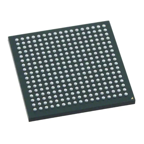
Figure 1. Spear300 Top View
56
Main Features
57
Architecture Properties
58
System Architecture Overview
59
Core Architecture
59
Figure 2. Spear300 - Core Architecture Overview
59
CPU Subsystem
60
Multilayer Bus Matrix
60
Dynamic Memory Controller
60
Basic Subsystem
61
High Speed Connectivity Subsystem
61
Low Speed Connectivity Subsystem
61
Application Subsystem
62
Reconfigurable Logic Array Subsystem
62
Clock and Reset System
63
Pin Description
64
Required External Components
64
Dedicated Pins
64
Table 3. Master Clock, RTC, Reset and 3.3 V Comparator Pin Descriptions
64
Table 4. Power Supply Pin Description
65
Table 5. Debug Pin Descriptions
65
Table 6. Serial Memory Interface (SMI) Pin Description
66
Table 7. USB Pin Descriptions
66
Table 8. ADC Pin Description
67
Table 9. DDR Pin Description
68
Shared I/O Pins (Pl_Gpios)
70
PL_GPIO Pin Description
70
Alternate Functions
70
Boot Pins
70
Table 10. PL_GPIO Pin Description
70
Gpios
71
Multiplexing Scheme
71
Table 11. Booting Pins
71
Figure 3. Multiplexing Scheme
72
Table 12. Available Peripherals in each Configuration Mode
73
Table 13. PL_GPIO Multiplexing Scheme
74
PL_GPIO Pin Sharing for Debug Modes
79
Table 14. Table Shading
79
Table 15. Ball Sharing During Debug
80
Memory Map
82
Table 16. Main Memory Map
82
Table 17. Multi Layer CPU Subsystem
82
Table 18. Low Speed Subsystem
82
Table 21. Application Subsystem
82
Table 22. Reconfigurable Array Subsystem
82
CPU Subsystem_Arm926Ej-S
85
Overview
85
Functional Description
86
Main Function Description
86
Memory Management Unit
86
Figure 4. ARM926EJ-S Block Diagram
86
Caches and Write Buffer
87
Bus Interface Unit
87
CPU Subsystem_Vectored Interrupt Controller (VIC)
89
Overview
89
Block Diagram
89
Main Functions Description
90
Interrupt Request Logic
90
Non-Vectored FIQ Interrupt Logic
90
Figure 5. VIC Block Diagram
90
Non-Vectored IRQ Interrupt Logic
91
Vectored Interrupts
91
Interrupt Priority Logic
91
Software Interrupts
91
AHB Slave Interface
91
Interrupt Connection Table
92
Table 23. Interrupt Sources
92
How to Reduce Interrupt Latency
93
Programming Model
93
Register Map
93
Table 24. Interrupt Latency for Different Types of Interrupts
93
Table 25. VIC Interrupt Control Registers Summary
94
Table 26. VIC Vector Address Registers Summary
94
Register Description
95
VICIRQSTATUS Register
95
Table 27. VIC Interrupt Vector Control Registers Summary
95
Table 28. VIC Identification Registers Summary
95
VICFIQSTATUS Register
96
VICRAWINTR Register
96
VICINTSELECT Register
96
Table 29. VICIRQSTATUS Register Bit Assignments
96
Table 30. VICFIQSTATUS Register Bit Assignments
96
Table 31. VICRAWINTR Register Bit Assignments
96
VICINTENABLE Register
97
VICINTENCLEAR Register
97
VICSOFTINT Register
97
Table 32. VICINTSELECT Register Bit Assignments
97
Table 33. VICINTENABLE Register Bit Assignments
97
Table 34. VICINTENCLEAR Register Bit Assignments
97
VICSOFTINTCLEAR Register
98
VICPROTECTION Register
98
VICVECTADDR Register
98
Table 35. VICSOFTINT Register Bit Assignments
98
Table 36. VICSOFTINTCLEAR Register Bit Assignments
98
Table 37. VICPROTECTION Register Bit Assignments
98
VICDEFVECTADDR Register
99
VICVECTADDR Register
99
VICVECTCNTL Register
99
Peripheral Identification Registers
99
Table 38. VICVECTADDR Register Bit Assignments
99
Table 39. VICVECTCNTL Registers Bit Assignments
99
VICPERIPHID0 Register
100
VICPERIPHID1 Register
100
VICPERIPHID2 Register
100
Table 40. Peripheral Identification Registers Bit Assignments
100
Table 41. VICPERIPHID0 Register Bit Assignments
100
Table 42. VICPERIPHID1 Register Bit Assignments
100
VICPERIPHID3 Register
101
Identification Registers
101
VICPCELLID0 Register
101
VICPCELLID1 Register
101
Table 43. VICPERIPHID2 Register Bit Assignments
101
Table 44. VICPERIPHID3 Register Bit Assignments
101
Table 45. VICPCELLID0 Register Bit Assignments
101
Table 46. VICPCELLID1 Register Bit Assignments
101
VICPCELLID2 Register
102
VICPCELLID3 Register
102
Table 47. VICPCELLID2 Register Bit Assignments
102
Table 48. VICPCELLID3 Register Bit Assignments
102
Bus Interconnection Matrix
103
Table 49. Soc Interconnection Matrix Scheme
103
Table 50. Soc Interconnection Matrix
103
ICM
104
Table 51. ICM Master Layers (Initiator)
104
Figure 6. ICM Block Diagram
104
Table 52. ICM Slaves (Targets)
105
DDR Memory Controller (MPMC)
106
Overview
106
Signal Description
106
Table 53. External Memory Interface Signals
106
Figure 7. MPMC Block Diagram
106
Table 54. Internal Signals
107
Features Overview
108
Main Block Description
109
Figure 8. Memory Controller Architecture
109
AHB-Memory Controller Interfaces
110
Table 55. Configured AHB Settings
112
Figure 9. Wrapx Effective Transaction
114
Table 56. READ/WRITE Data Alignment - Little Endian
115
Table 57. READ/WRITE Data Alignment - Big Endian
116
Table 58. AHB-Memory Controller Translation Example
117
Arbiter
118
Write Data Queue
118
DRAM Command Processing
119
Latency
119
Multi-Port Arbiter
120
Arbitration Overview
121
Understanding Round-Robin Operation
121
Understanding Port Priority
122
Understanding Relative Priority
122
Table 59. Round-Robin Operation Example
122
Figure 10. Weighted Round-Robin Priority Group Structure
123
Understanding Port Ordering
124
Table 60. Relative Priority Example
124
Weighted Round-Robin Arbitration Summary
125
Table 61. Port Ordering Example
125
Table 62. System D Specifications
125
Table 63. System D Operation
126
Table 64. System E Specifications
126
Priority Relaxing
127
Table 65. System E Operation
127
Table 66. System F Specifications
128
Table 67. System F Operation with Priority Relaxing
128
Port Pairing
129
Table 68. System G Specifications
130
Table 69. System G Operation
130
Error Conditions
131
Command Queue with Placement Logic
131
Core Command Queue with Placement Logic
132
Rules of the Placement Algorithm
132
Command Execution Order after Placement
134
Low Power Operation
135
Low Power Modes
135
Low Power Mode Control
136
Table 70. Low Power Mode Parameters
138
Table 71. Low Power Mode Controls
139
Additional Features
140
Out-Of-Range Address Checking
140
Mobile Devices DQS
141
Half Datapath Option
141
Table 72. Memory Interface Buses with Half Datapath Option
141
User-Defined Registers
142
Address Mapping
142
DDR SDRAM Address Mapping Options
142
Maximum Address Space
143
Memory Mapping to Address Space
143
Figure 11. Memory Map: Maximum
143
Figure 12. Alternate Memory Map
143
DCC Tuning Timing
144
Table 73. Delay Parameters
144
External Pin Connection of DDR Interface in Spear300
145
Initialization Protocol
145
Table 74. MT47H128M8-3 (DDR2@333 Mhz Cl5) Initialization Table
146
Table 75. MT46H6M16LF-6(Low Power DDR @166 Mhz Cl3) Initialization Table
147
Register Interface
149
Register Overview
149
MPMC Base Address in Spear300
149
Register Map
149
Table 76. Parameter Size to Mapping Conditions
149
Table 77. Registers Overview
150
Register Description
156
MEM0_CTL Register
156
Table 78. MEM0_CTL Register Bit Assignments
156
MEM1_CTL Register
157
MEM2_CTL Register
157
Table 79. MEM1_CTL Register Bit Assignments
157
Table 80. MEM2_CTL Register Bit Assignments
157
MEM3_CTL Register
158
MEM4_CTL Register
158
Table 81. MEM3_CTL Register Bit Assignments
158
Table 82. MEM4_CTL Register Bit Assignments
158
10.13.10 MEM5_CTL Register
159
10.13.11 MEM6_CTL Register
159
Table 83. MEM5_CTL Register Bit Assignments
159
Table 84. MEM6_CTL Register Bit Assignments
159
Table 85. MEM7_CTL Register Bit Assignments
160
Table 86. MEM8_CTL Register Bit Assignments
160
Table 87. MEM9_CTL Register Bit Assignments
161
Table 88. MEM10_CTL Register Bit Assignments
161
Table 89. MEM11_CTL Register Bit Assignments
162
Table 90. MEM12_CTL Register Bit Assignments
162
Table 91. MEM13_CTL Register Bit Assignments
163
Table 92. MEM14_CTL Register Bit Assignments
163
MEM13_CTL Register
163
Table 93. MEM15_CTL Register Bit Assignments
164
Table 94. MEM16_CTL Register Bit Assignments
164
Table 95. MEM17_CTL Register Bit Assignments
164
MEM15_CTL Register
164
Table 96. MEM18_CTL Register Bit Assignments
165
Table 97. MEM19_CTL Register Bit Assignments
165
MEM18_CTL Register
165
Table 98. MEM20_CTL Register Bit Assignments
166
Table 99. MEM21_CTL Register Bit Assignments
166
Table 100. MEM22_CTL Register Bit Assignments
167
Table 101. MEM23_CTL Register Bit Assignments
167
Table 102. MEM24_CTL Register Bit Assignments
168
Table 103. MEM25_CTL Register Bit Assignments
168
Table 104. MEM26_CTL Register Bit Assignments
169
Table 105. MEM27_CTL Register Bit Assignments
169
Table 106. MEM28_CTL Register Bit Assignments
170
Table 107. MEM29_CTL Register Bit Assignments
170
Table 108. MEM30_CTL Register Bit Assignments
171
Table 109. MEM31_CTL/MEM32_CTL/MEM33_CTL Register Bit Assignments
171
Table 110. MEM34_CTL Register Bit Assignments
171
Table 111. MEM35_CTL Register Bit Assignments
172
Table 112. MEM36_CTL Register Bit Assignments
172
Table 113. MEM37_CTL Register Bit Assignments
172
Table 114. MEM38_CTL Register Bit Assignments
173
Table 115. MEM39_CTL Register Bit Assignments
173
Table 116. MEM40_CTL Register Bit Assignments
174
Table 117. MEM41_CTL Register Bit Assignments
174
Table 118. MEM42_CTL Register Bit Assignments
174
Table 119. MEM43_CTL Register Bit Assignments
175
Table 120. MEM44_CTL Register Bit Assignments
175
Table 121. MEM45_CTL Register Bit Assignments
175
Table 122. MEM46_CTL Register Bit Assignments
176
Table 123. MEM47_CTL Register Bit Assignments
176
Table 124. MEM48_CTL Register Bit Assignments
176
Table 125. MEM49_CTL Register Bit Assignments
177
Table 126. MEM50_CTL Register Bit Assignments
177
Table 127. MEM51_CTL Register Bit Assignments
177
Table 128. MEM52_CTL/MEM53_CTL Register Bit Assignments
178
Table 129. MEM54_CTL Register Bit Assignments
178
Table 130. MEM55_CTL Register Bit Assignments
178
Table 131. MEM56_CTL Register Bit Assignments
178
Table 132. MEM57_CTL Register Bit Assignments
178
Table 133. MEM58_CTL Register Bit Assignments
179
Table 134. MEM59_CTL Register Bit Assignments
179
Table 135. MEM60_CTL Register Bit Assignments
179
Table 136. MEM61_CTL Register Bit Assignments
179
Table 137. MEM62_CTL/MEM63_CTL/MEM64_CTL Register Bit Assignments
180
Table 138. MEM65_CTL Register Bit Assignments
180
Table 139. MEM66_CTL Register Bit Assignments
180
Table 140. MEM67_CTL Register Bit Assignments
180
Table 141. MEM68_CTL Register Bit Assignments
181
Table 142. MEM[69-97]_CTL Register Bit Assignments
181
Table 143. MEM[98-99]_CTL Register Bit Assignments
181
Table 144. MEM100_CTL Register Bit Assignments
182
Table 145. MEM101_CTL Register Bit Assignments
182
Table 146. MEM102_CTL Register Bit Assignments
183
Table 147. MEM103_CTL Register Bit Assignments
183
Table 148. MEM104_CTL Register Bit Assignments
183
Table 149. MEM105_CTL Register Bit Assignments
184
Table 150. MEM106_CTL Register Bit Assignments
184
Table 151. MEM107_CTL Register Bit Assignments
184
Table 152. MEM108_CTL Register Bit Assignments
184
Table 153. Memory Controller Parameters
185
Clock & Reset System
201
Table 154. Jitter at PLL Output Clock
202
Figure 13. Clock Generation Scheme
202
Figure 14. Processor Clock
203
Figure 15. DDR Controller Clock
203
Clock Distribution Scheme
203
Figure 16. RAS Block Diagram
204
Bus Clocks
204
Figure 17. I2S Clock Schematic
205
Figure 18. Telecom Clock Schematic
205
Clock Synthesizer
205
Figure 19. Main Crystal Connection
207
Figure 20. RTC Crystal Connection
207
Table 155. APB Interface Signals
208
Figure 21. Top View of Miscellaneous Registers
208
Signal Description
208
Table 156. Miscellaneous Register Main Memory Map
209
Overview Features
209
Table 157. Miscellaneous Local Space Registers Overview
210
Table 158. Soc_Cfg_Ctr Register Bit Assignments
213
Table 159. DIAG_CFG_CTR Register Bit Assignments
216
PLL 1/2_CTR Registers
218
Table 160. PLL 1/2_CTR Register Bit Assignments
219
Table 161. PLL1/2_FRQ Register Bit Assignments
220
PLL1/2_FRQ Registers
220
PLL1/2_MOD Registers
221
Table 162. PLL1/2_MOD Register Bit Assignments
222
PLL_CLK_CFG Register
222
Table 163. PLL_CLK_CFG Register Bit Assignments
223
Table 164. CORE_CLK_CFG Register Bit Assignments
225
PRPH_CLK_CFG Register
226
Table 165. PRPH_CLK_CFG Register Bit Assignments
227
Table 166. PERIP1_CLK_ENB Register Bit Assignments
228
Table 167. RAS_CLK_ENB Register Bit Assignments
230
PRSC1/2/3_CLK_CFG Register
231
Table 168. PRSC1/2/3_CLK_CFG Register Bit Assignments
232
Table 169. AMEM_CFG_CTRL Register Bit Assignments
232
Table 170. Clock Synthesizer Input Frequency
233
Auxiliary Clock Synthesizer Registers
233
Table 171. Auxiliary Clock Synthesizer Register Bit Assignments
234
Soft Reset Control
234
Table 172. PERIP1_SOF_RST Register Bit Assignments
235
RAS_SOF_RST Register
236
Table 173. RAS_SOF_RST Register Bit Assignments
237
Table 19. Basic Subsystem
238
Table 20. High Speed Subsystem
238
Table 174. Interconnection Matrix
238
Table 175. ICM 1-9_ARB_CFG Register Bit Assignments
238
Soc Configuration Basic Parameters
238
DMA_CHN_CFG Register
240
Table 176. DMA_CHN_CFG Register Bit Assignment
241
USB2_PHY_CFG Register
241
Table 177. USB2_PHY_CFG Register Bit Assignments
242
Table 178. MAC_CFG_CTR Register Bit Assignments
242
Table 179. Powerdown_Cfg_Ctr Register Bit Assignments
243
Special Configuration Parameters
243
Table 180. COMPSSTL_1V8_CFG/DDR_2V5_COMPENSATION Register Bit Assignments
244
Table 181. COMPCOR_3V3_CFG Register Bit Assignments
245
Table 182. DDR_PAD Register Bit Assignments
245
Table 183. BIST1_CFG_CTR Register Bit Assignments
247
Memory bist Execution Control
247
BIST2_CFG_CTR Register
249
Table 184. BIST2_CFG_CTR Register Bit Assignments
250
BIST3_CFG_CTR Register
250
Table 185. BIST3_CFG_CTR Register Bit Assignments
251
BIST4_CFG_CTR Register
251
Table 186. BIST4_CFG_CTR Register Bit Assignments
252
BIST1_STS_RES Register
252
Table 187. BIST1_STS_RES Register Bit Assignments
253
Table 188. BIST2_STS_RES Register Bit Assignments
254
BIST3_STS_RES Register
255
Table 189. BIST3_STS_RES Register Bit Assignments
256
Table 190. BIST4_STS_RES Register Bit Assignments
257
BIST5_RSLT_REG Register (Reserved)
258
Table 191. BIST5_RSLT_REG Register Bit Assignments
259
Table 192. SYSERR_CFG_CTR Register Bit Assignments
260
Diagnostic Functionality
260
Table 193. USB_TUN_PRM Register Bit Assignments
262
Table 194. Drive Selection
262
Table 195. Pull up and Pull down Selection
263
Table 196. Slew Selection
263
Table 197. PLGPIO0_PAD_PRG Register Bit Assignments
263
Table 198. PLGPIO1_PAD_PRG Register Bit Assignments
264
Table 199. PLGPIO2_PAD_PRG Register Bit Assignments
265
Table 200. PLGPIO3_PAD_PRG Register Bit Assignments
266
Table 201. PLGPIO4_PAD_PRG Register Bit Assignments
267
Miscellaneous Register Global Space
267
Miscellaneous Register Global Space Address Map
268
Table 202. Miscellaneous Global Space Registers Overview
268
Table 203. RAS_GPP1_IN Register Bit Assignments
268
Table 204. RAS_GPP2_IN Register Bit Assignments
268
RAS1/2_GPP_OUT Register
269
Table 205. RAS_GPP_EXT_IN Register Bit Assignments
269
Table 206. RAS_GPP1_OUT Register Bit Assignments
269
Table 207. RAS_GPP2_OUT Register Bit Assignments
269
Table 208. RAS_GPP_EXT_OUT Register Bit Assignments
269
Figure 22. SPI Block Diagram
270
Overview
270
Signal Interfaces
271
Table 209. SSP Signal Interface
271
Register Block
272
Interrupt Generation Logic
273
Enable SSP Operation
274
Table 210. External CS Selection
274
Programming the SSPCR0 Control Register
275
Frame Format
276
Programming Model
277
Table 211. External Pin Connection
277
Table 212. SSP Registers Summary
277
Table 213. SSPCR0 Register Bit Assignments
278
Table 214. SSPCR1 Register Bit Assignments
279
Table 215. SSPDR Register Bit Assignments
280
Table 216. SSPSR Register Bit Assignments
280
Table 217. SSPCPSR Register Bit Assignments
281
Table 218. SSPIMSC Register Bit Assignments
281
Table 219. SSPRIS Register Bit Assignments
281
Table 220. SSPMIS Register Bit Assignments
282
Table 221. SSPICR Register Bit Assignments
282
Table 222. SSPDMACR Register Bit Assignments
283
Table 223. PHERIPHID0 Register Bit Assignments
283
Table 224. PHERIPHID1 Register Bit Assignment
283
Table 225. PHERIPHID2 Register Bit Assignments
283
Table 226. PHERIPHID3 Register Bit Assignments
283
Table 227. PCELLID0 Register Bit Assignments
284
Table 228. PCELLID1 Register Bit Assignment
284
Table 229. PCELLID2 Register Bit Assignment
284
Table 230. PCELLID3 Register Bit Assignment
284
Ssprxintr
285
Overview
286
Figure 23. System Controller Block Diagram
287
Figure 24. System Mode Control State Machine
290
Interrupt Response Mode
291
Programming Model
292
Table 231. System Controller Control and Status Registers Summary
292
Table 232. System Controller Identification Registers Summary
292
Register Description
293
Table 233. SCCTRL Register Bit Assignments
293
SCSYSSTAT Register
294
Table 234. SCIMCTRL Register Bit Assignments
295
Table 235. SCIMSTAT Register Bit Assignments
295
Table 236. SCXTALCTRL Register Bit Assignments
296
Table 237. SCPLLCTRL Register Bit Assignments
296
Overview
298
Figure 25. SMI Block Diagram
299
Main Functions Description
299
Operation Modes
300
Table 238. SMI Supported Instruction
300
Figure 26. External SPI Memory Map in AHB Address Space
301
Software Mode
301
Write Request
302
Write Burst Mode
303
Erase and Write Status Register
304
How to Boot from External Memory
305
Table 239. External Pin Connection
306
Table 240. SMI Registers Summary
306
Table 241. SMI_CR1 Register Bit Assignments
306
Programming Model
306
Table 242. SMI_CR2 Register Bit Assignments
308
SMI_SR Register
309
Table 243. SMI_SR Register Bit Assignments
310
Table 244. SMI_TR Register Bit Assignments
311
Table 245. SMI_RR Register Bit Assignments
312
Figure 27. Watchdog Module Block Diagram
313
Overview
313
Main Functions Description
314
Table 246. Watchdog Module Counter Decremented
314
Programming Model
315
Table 247. Watchdog Control and Status Registers Summary
315
Table 248. Watchdog Identification Registers Summary
315
Register Description
316
Table 249. Wdogcontrol Register Bit Assignments
316
Table 250. Wdogris Register Bit Assignments
317
Table 251. Wdogmis Register Bit Assignments
317
Table 252. Wdoglock Register Bit Assignments
317
Overview
318
Table 253. External Pin Connection
318
Figure 28. GPT Block Diagram
319
Register Map
320
Table 254. GPT Interface Signal Description
320
Register Description
321
Table 255. Couple of Gpts Registers Summary
321
Table 256. Timer_Control Register Bit Assignments
321
Table 257. PRESCALER Configuration
322
TIMER_STATUS_INT_ACK Register
322
Table 258. TIMER_STATUS_INT_ACK Register Bit Assignments
323
Table 259. TIMER_COMPARE Register Bit Assignments
323
Table 260. TIMER_COUNT Register Bit Assignments
324
Table 261. TIMER_REDG_CAPT Register Bit Assignments
324
Table 262. TIMER_FEDG_CAPT Register Bit Assignments
324
Figure 29. GPIO Block Diagram
325
Overview
325
Table 263. GPIO Signal Interface
325
Figure 30. GPIO Signal Interfaces Diagram
326
Main Functions Description
326
Mode Control
327
Figure 31. GPIO Interrupt Triggering Logic
328
Programming Model
328
Table 264. GPIO Data Direction Register
329
Table 265. GPIO Data Register
329
Table 266. GPIO Interrupt Control Registers Summary
329
Table 267. GPIO Identification Registers Summary
329
Register Description
330
Table 268. GPIODIR Register Bit Assignments
330
Table 269. GPIODATA Register Bit Assignments
330
Table 270. GPIOIS Register Bit Assignments
330
Table 271. GPIOIBE Register Bit Assignments
331
Table 272. GPIOIEV Register Bit Assignments
331
Table 273. GPIOIE Register Bit Assignments
331
Table 274. GPIORIS Register Bit Assignments
332
Table 275. GPIOMIS Register Bit Assignments
332
Table 276. GPIOIC Register Bit Assignments
332
Overview
333
Figure 32. DMAC Block Diagram
334
Figure 33. DMAC Signal Interface Diagram
334
Main Functions Description
335
Table 277. DMAC Signal Interface
335
DMA Interface
336
Figure 34. DMAC-To-Interrupt Controller Connection
337
How to Program the DMAC for Scatter/Gather DMA
337
How to Operate Single Combined DMACINTR Interrupt Request Signal
338
Table 278. DMAC Global Registers Summary
338
Table 279. DMAC Channel Registers Summary
339
Table 280. DMAC Peripheral Registers Summary
339
Table 281. DMAC Cell Identification Registers Summary
339
Register Description
340
Table 282. Dmacintstatus Register Bit Assignments
340
Table 283. Dmacinttcstatus Register Bit Assignments
340
Dmacinterrorstatus Register
341
Table 284. Dmacinttcclear Register Bit Assignments
341
Table 285. DMA Clnterrorstatus Register Bit Assignments
341
Table 286. Dmacinterrclr Register Bit Assignments
341
Table 287. Dmacrawinttcstatus Register Bit Assignments
342
Table 288. Dmacrawinterrorstatus Register Bit Assignments
342
Table 289. Dmacenbldchns Register Bit Assignments
342
Table 290. Dmacsoftbreq Register Bit Assignments
343
Table 291. Dmacsoftsreq Register Bit Assignments
343
Table 292. Dmacsoftlbreq Register Bit Assignments
344
Table 293. Dmacsoftlsreq Register Bit Assignments
344
Table 294. Dmacconfiguration Register Bit Assignments
344
Table 295. Dmacsync Register Bit Assignments
345
Table 296. Dmaccnsrcaddr Register Bit Assignments
346
Table 297. Dmaccndestaddr Register Bit Assignments
346
Table 298. Dmaccnlli Register Bit Assignments
346
Dmaccn Control Register
347
Table 299. Dmaccncontrol Register Bit Assignments
347
Table 300. DMAC Configuration Register Bit Assignments
349
Dmacperiphid Register
351
Overview
352
Table 301. RTC Functional Registers Summary
352
Table 302. CONTROL Register Bit Assignments
353
Table 303. STATUS Register Bit Assignments
353
Table 304. TIME Register Bit Assignments
354
Table 305. DATE Register Bit Assignments
355
Table 306. ALARM TIME Register Bit Assignments
355
ALARM DATE Registers
356
Table 307. ALARM DATE Register Bit Assignments
356
Table 308. REG1MC Registers Bit Assignments
356
Table 309. REG2MC Register Bit Assignments
356
Overview
357
Functional Description
358
Table 310. C3 Device Summary
358
Figure 35. C3 Block Diagram
359
HIF (High Speed Bus Interface)
360
CCM (Coupling/Chaining Module)
361
Table 311. C3 Components System Register Summary
362
Processing Overview
362
System Registers (C3_SYS)
363
Table 312. C3 Components System Registers Map
364
Register Configuration
364
Master Interface Register (C3_HIF)
368
Table 313. AHB Mapped Registers for Master Interface (HIF)
369
Register Configuration
369
Register Description
370
Memory Base Address Register (HIF_MBAR)
371
Memory Page Base Address Register (HIF_MPBAR)
373
Memory Access Address Register (HIF_MAAR)
374
Memory Access Data Register (HIF_MADR)
375
Byte Bucket Control Register (HIF_NCR)
376
Table 314. AHB Mapped Registers for an Instruction Dispatcher (ID)
377
Table 315. AHB Mapped Registers for Channel (CH)
382
Channel Registers (C3_Chn)
382
Table 316. Channel ID Table
383
DES Channel
383
Table 317. des ECB Start Instruction Bit Encoding
384
Table 318. des ECB Bit 'A' Encoding
384
Table 319. des ECB Bit 'B' Encoding
384
Table 320. des CBC START Instruction Bit Encoding
384
Table 321. des ECB APPEND Instruction Bit Encoding
385
Register Set
386
Table 322. des CBC Append Instruction Bit Encoding
386
Table 323. des Registers Map
386
Feedback Registers (DES_FEEDBACK)
387
Tkey Registers (DES_KEY)
388
Table 324. AES ECB START Instruction Bit Encoding
389
Table 325. AES ECB Bit 'A' Encoding
389
Table 326. AES CBC START Instruction Bit Encoding
389
Table 327. AES CTR START Instruction Bit Encoding
390
Table 328. AES ECB APPEND Instruction Bit Encoding
390
Register Configuration
391
Table 329. AES CBC APPEND Instruction Bit Encoding
391
Table 330. AES CTR APPEND Instruction Bit Encoding
391
Table 331. AES Registers Map
391
Data Input/Output Registers (AES_DATAIN_OUT)
392
Counter Registers (AES_COUNTER)
393
Key Registers (AES_KEY)
395
Init
396
Table 332. HASH INIT Instruction Bit Encoding
396
Table 333. HASH INIT Bit 'Aa' Encoding
396
Table 334. HASH APPEND Instruction Bit Encoding
396
Table 335. HASH END Instruction Bit Encoding
397
Table 336. HASH CONTEXT SAVE Instruction Bit Encoding
397
Table 337. HASH CONTEXT RESTORE Instruction Bit Encoding
397
Table 338. HMAC INIT Instruction Bit Encoding
398
Table 339. HMAC APPEND Instruction Bit Encoding
398
HMAC CONTEXT Instruction
399
Table 340. HMAC END Instruction Bit Encoding
399
Restore
400
Table 341. HMAC CONTEXT SAVE Instruction Bit Encoding
400
Table 342. HMAC CONTEXT RESTORE Instruction Bit Encoding
400
Table 343. UHH Channel Registers Map
400
Register Description
402
Data Input Register (UHH_DATA_IN)
405
Channel ID (UHH_CH_ID)
410
Overview
411
Figure 36. UHC Block Diagram
412
OHCI Host Controller
413
Root Hub
414
Figure 37. USB Host Controller (UHOSTC) Block Diagram
415
HCI Master Block
415
List Processor Block
416
Table 344. External Pin Connections
417
Roothub Port Configuration
417
Table 345. UHC Registers' Base Address
418
Register Map
418
Table 346. EHCI Host Controller Capability Registers Summary
419
Table 347. EHCI Host Controller Operational Registers Summary
419
Table 348. EHCI Host Controller Auxiliary Power Well Registers Summary
419
Table 349. EHCI Host Controller Specific Registers Summary
420
Table 350. Host Controller Operational Registers
420
Table 351. HCCAPBASE Register Bit Assignments
421
Table 352. HCSPARAMS Register Bit Assignments
421
Register Descriptions of EHCI
421
Table 353. HCCPARAMS Register Bit Assignments
423
USBCMD Register
424
Table 354. USBCMD Register Bit Assignments
425
Table 355. USBSTS Register Bit Assignments
428
Table 356. USBINTR Register Bit Assignments
430
Table 357. FRINDEX Register Bit Assignments
431
Table 358. USBCMD Register Encoding
432
CTRLDSSEGMENT Register
432
Table 359. PERIODICLISTBASE Register Bit Assignments
433
Table 360. ASYNCLISTADDR Register Bit Assignments
433
SYNCLISTADDR Register
433
Table 361. CONFIGFLAG Register Bit Assignments
434
Table 362. PORTSC Register Bit Assignments
434
PORTSC Registers
434
INSNREG00 Register
439
Table 363. INSNREG01 Register Bit Assignments
440
Table 364. INSNREG03 Register Bit Assignments
440
Table 365. INSNREG05 Register Bit Assignments
440
INSNREG02 Register
440
Table 366. Hcrevision Register Bit Assignments
441
Table 367. Hccontrol Register Bit Assignments
441
The Control and Status Partition
441
Hccommandstatus Register
443
Table 368. Hccommandstatus Register Bit Assignments
444
Hcinterruptstatus Register
445
Table 369. Hcinterruptstatus Register Bit Assignments
446
Table 370. Hcinterruptenable Register Bit Assignments
447
Table 371. Hcinterruptdisable Register Bit Assignments
448
Memory Pointer Partition
448
Table 372. Hchcca Register Bit Assignments
449
Table 373. Hcperiodcurrented Register Bit Assignments
449
Table 374. Hccontrolheaded Register Bit Assignments
449
Table 375. Hccontrolcurrented Register Bit Assignments
450
Table 376. Hcbulkheaded Register Bit Assignments
450
Table 377. Hcbulkcurrented Register Bit Assignments
451
Table 378. Hcdonehead Register Bit Assignments
451
Table 379. Hcfminterval Register Bit Assignments
452
Table 380. Hcfmremaining Register Bit Assignments
452
Table 381. Hcfmnumber Register Bit Assignments
453
Table 382. Hcperiodicstart Register Bit Assignments
453
Table 383. Hclsthreshold Register Bit Assignments
454
Root Hub Partition
454
Table 384. Hcrhdescriptora Register Bit Assignments
455
Hcrhdescriptorb Register
456
Table 385. Hcrhdescriptorb Register Bit Assignments
457
Table 386. Hcrhstatus Register Bit Assignments
457
Hcrhportstatus[1:Ndp] Register
458
Table 387. Hcrhportstatus Register Bit Assignments
459
Table 388. Endpoints Assignment
463
Overview
463
Figure 38. UDC-AHB Subsystem Block Diagram Within the USB 2.0 Device
464
Figure 39. Udc_Device Block Diagram
464
Main Functions Description
465
SOF Tracker
466
Figure 40. Rxfifo Implementation
467
Endpoint FIFO Controller (Transmit FIFO Controller)
467
Control and Status Registers
468
DMA Controller
469
Theory of Operation
470
Figure 41. Linked-List Memory Structure in DMA Mode
471
In Operation (Data Transfer to USB Host)
471
Figure 42. in Transaction Flow in DMA Mode
473
Out Operation (Data Transfer from USB Host)
473
Figure 43. out Transaction Flow in DMA Mode
474
Slave-Only Mode
474
Figure 44. in Transaction Flow in Slave-Only Mode
476
Figure 45. out Transaction Flow in Slave-Only Mode
477
Figure 46. SETUP Data Memory
478
Table 389. SETUP Data Memory: Status Quadlet Bit Assignments
478
Data Memory Structure in DMA Mode
478
Figure 47. out Data Memory
479
Table 390. out Data Memory: Buffer Status Quadlet Bit Assignments (for Non-Isochronous OUT)
480
IN Data Memory Structure
481
Table 391. out Data Memory: Buffer Status Quadlet Bit Assignments (for Isochronous OUT)
481
Figure 48. in Data Memory
482
Table 393. in Data Memory:buffer Status Quadlet Bit Assignments (for Isochronous)
483
Operation Modes in DMA Mode
484
Burst Split Enable
485
Programming Model
486
Table 394. Plug Status Register Bit Assignments
486
Table 395. Plug Pending Register Bit Assignments
486
Table 396. in Endpoint-Specific Csrs Summary
487
Table 397. out Endpoint-Specific Csrs Summary
488
Table 398. Global Csrs Summary
488
Table 399. Udcl Csrs Summary
489
Figure 49. UDC-AHB Subsystem Memory Map
490
Register Description
490
Table 400. Device Configuration Register Bit Assignments
490
Table 401. Device Control Register Bit Assignments
492
Table 402. Device Status Register Bit Assignments
494
Device Interrupt Register
495
Table 403. Device Interrupt Register Bit Assignments
496
Table 404. Device Interrupt Mask Register Bit Assignments
497
Table 405. Endpoint Interrupt Register Bit Assignments
497
Table 406. Endpoint Interrupt Mask Register Bit Assignments
497
Table 407. Endpoint Control Register Bit Assignments
498
Endpoint Status Register
499
Table 408. Endpoint Status Register Bit Assignments
500
Table 409. Endpoint Buffer Size/Received Packet Frame Number Register Bit Assignments
501
Endpoint Maximum Packet Size and Buffer Size Register
502
Table 410. Endpoint Maximum Packet Size/Buffer Size Register Bit Assignments
503
Table 411. Endpoint SETUP Buffer Pointer Register Bit Assignments
503
Table 412. Endpoint Data Description Pointer Register Bit Assignments
503
Table 413. Endpoint Register Bit Assignments
503
Overview
505
Figure 50. MAC-UNIV (MAC-AHB Configuration) System-Level Block Diagram
506
Main Functions Description
506
DMA Controller
507
Power Management Module (PMT)
508
Figure 51. DMA Descriptor List: Ring Structure (Left) and Chain Structure (Right)
509
Transmit Descriptors
509
Figure 52. DMA Descriptor Format (Transmit Descriptor, 32 Bit)
510
Table 414. Transmit Descriptor 0 (TDES0)
510
Table 415. Transmit Descriptor 1 (TEDS1)
512
Table 416. Transmit Descriptor 2 (TDES2)
512
Table 417. Transmit Descriptor 3 (TDES3)
512
Figure 53. DMA Descriptor Format (Receive Descriptor, 32 Bit)
513
Receive Descriptors
513
Table 418. Receive Descriptor 0 (RDES0)
513
Table 419. Receive Descriptor 1 (RDES1)
514
Table 420. Receive Descriptor 2 (RDES2)
515
Table 421. Receive Descriptor 3 (RDES3)
515
How to Initialize DMA
515
Figure 54. Interrupt Management: Sbd_Intr_O and Pmt_Intr_O Generation
516
Table 422. MAC-UNIV DMA Registers Summary
517
Table 423. MAC-UNIV MAC Global Registers Summary
517
Programming Model
517
Table 424. MMC (MAC Management Counters) Registers
518
Register Description
521
Table 425. Bus Mode Register Bit Assignments
522
Table 426. Transmit Poll Demand Register Bit Assignments
523
Table 427. Receive Poll Demand Register Bit Assignments
523
Transmit Poll Demand Register (Register1, DMA)
523
Table 428. Receive Descriptor List Address Register Bit Assignments
524
Table 429. Transmit Descriptor List Address Register Bit Assignments
524
Table 430. Status Register Bit Assignments
525
Table 431. EB Field Bit Assignments
526
Table 432. TS Filed Bit Assignments
526
Table 433. RS Field Bit Assignments
527
Table 434. NIS Field Bit Assignments
527
Table 435. AIS Field Bit Assignments
527
Operation Mode Register (Register 6, DMA)
529
Table 436. Operation Mode Register Bit Assignments
530
Table 437. TTC Field Bit Assignments
530
Table 438. RFD Field Bit Assignments
531
Table 439. RFA Field Bit Assignments
531
Interrupt Enable Register (Register7, DMA)
532
Table 440. RTC Field Bit Assignments
532
Table 441. Interrupt Enable Register Bit Assignments
532
Table 442. Missed Frame and Buffer Overflow Counter Register Bit Assignments
533
Current Host Receive Descriptor Register (Register19, DMA)
534
Table 443. MAC Configuration Register Bit Assignments
535
Table 444. IFG Field Bit Assignments
536
MAC Frame Filter Register (Register1, MAC)
537
Table 445. BL Field Bit Assignments
537
Table 446. MAC Frame Filter Register Bit Assignments
538
Hash Table High Register (Register2, MAC)
539
Table 447. PCF Field Bit Assignments
539
MII Address Register (Register4, MAC)
540
Table 448. MII Address Register Bit Assignments
540
MII Data Register (Register5, MAC)
541
Table 449. CR Field Bit Assignments
541
Table 450. MII Data Register Bit Assignments
541
Table 451. Flow Control Register Bit Assignments
542
Table 452. PLT Field Bit Assignments
542
Table 453. VLAN Tag Register Bit Assignments
543
VLAN Tag Register (Register7, MAC)
543
Figure 55. Wake-Up Frame Filter Registers
544
PMT Control and Status Register (Register11, MAC)
544
Table 454. 4 Bit Command Registers
544
Interrupt Status Register (Register 14, MAC)
545
Table 455. PMT CSR Bit Assignments
545
Table 456. Interrupt Status Register Bit Assignments
545
Interrupt Mask Register (Register 15, MAC)
546
Table 457. Interrupt Mask Register Bit Assignments
546
Table 458. MAC Address0 High Register Bit Assignments
546
MAC Address1 High Register (Register18, MAC)
547
Table 459. MAC Address0 Low Register Bit Assignments
547
Table 460. MAC Address1 High Register Bit Assignments
547
Table 461. MAC Address Byte
547
MAC Address1 Low Register (Register19, MAC)
548
Table 462. MAC Address1 Low Register Bit Assignments
548
Table 463. MMC Control Register Bit Assignments
548
Table 464. MMC Receive Interrupt Register Bit Assignments
549
Table 465. MMC Transmit Interrupt Register Bit Assignments
550
Table 466. MMC Receive Interrupt Mask Register Bit Assignments
552
Clocks with MII
553
Figure 56. Clocking Scheme for MAC-AHB
554
Table 467. GPIO Signal Interface
555
Overview
555
Figure 57. JPGC Signal Interfaces Diagram
556
Figure 58. JPGC Block Diagram
556
Functional Description
556
Main Functions Description
557
FIFO Buffers
558
Table 468. JPGC Memory Map
558
Table 469. JPGC Codec Core Registers
559
Table 470. JPGC Codec Controller Registers
559
Table 471. JPGC FIFO Registers
559
Register Description
560
Table 472. JPGC Internal Memories
560
Table 473. Jpgcreg0 Register Bit Assignments
560
Jpgcreg2 Register
561
Table 474. Jpgcreg1 Register Bit Assignments
561
Table 475. Jpgcreg2 Register Bit Assignments
562
Table 476. Jpgcreg3 Register Bit Assignments
562
JPGC Control Status Register
563
Table 477. Jpgcreg4-7 Register Bit Assignments
563
Table 478. JPGC Control Status Register Bit Assignments
564
Table 479. JPGC Bytes from Fifo to Core Register Bit Assignments
564
Table 480. JPGC Bytes from Core to Fifo Register Bit Assignments
565
Table 481. Jpgcbust Count before Init Register Bit Assignments
565
Jpgcfifoout Register
566
Table 482. JPGC Fifo in Register Bit Assignments
566
Table 483. JPGC Fifo out Register Bit Assignments
566
Table 484. Jpgcqmem Memory Map
566
Table 485. Jpgchuffmin Memory Map
567
Table 486. JPGC Huffbase Memory Map
567
Table 487. JPGC Huffsymb Memory Map
567
Table 488. Jpgcdhtmem Memory Map
568
Table 489. Jpgchuffenc Memory Map
569
Table 490. Location of AC Huffman Codes in Jpgchuffenc Memory
569
Table 491. Location of DC Huffman Codes in Jpgchuffenc Memory
570
Overview
571
Figure 59. Dataflow Block Diagram of the Firda Controller
572
Main Functions Description
572
Demodulation Unit
573
Modulation Unit
574
FIFO Unit
575
Table 492. Settings of K,L and (N+1) Parameters for SIR,MIR and FIR in Baud Rate Generation Unit
575
Table 493. Request Signals
575
Interrupt Sources
577
Table 494. Firda Controller Interrupt Summary
577
Table 496. Firda Controller Control and Status Registers Summary
578
Table 497. Firda Controller Data Registers Summary
578
Table 498. Firda Controller Interrupt and DMA Registers Summary
578
Programming Model
578
Register Description
579
Table 499. Irda_Con Register Bit Assignments
579
Table 500. Irda_Conf Register Bit Assignments
579
Irda_Para Register
580
Irda_Dv Register
581
Table 501. Irda_Para Register Bit Assignments
581
Table 502. Irda_Dv Register Bit Assignments
582
Table 503. Irda_Stat Register Bit Assignments
582
Table 504. Irda_Tfs Register Bit Assignments
583
Table 505. Irda_Rfs Register Bit Assignments
583
Table 506. Irda_Txb Register Bit Assignments
584
Table 507. Irda_Rxb Register Bit Assignments
584
Table 508. Irda_Imsc Register Bit Assignments
584
Irda_Mis Register
585
Table 509. Irda_Ris Register Bit Assignments
585
Table 510. Irda_Mis Register Bit Assignments
586
Table 511. Irda_Icr Register Bit Assignments
586
Table 512. Irda_Isr Register Bit Assignments
587
Table 513. Irda_Dma Register Bit Assignments
587
Overview
589
Figure 60. UART Block Diagram
590
Functional Description
590
Table 514. UART Interrupt Summary Together with Combined Outputs
592
Table 515. UART Base Address
594
Table 516. UART Data Registers Summary
594
Table 517. UART Error Status/Clear Registers Summary
594
Table 518. UART Control and Status Register Summary
594
Programming Model
594
Register Description
595
Table 519. UART Interrupts and DMA Registers Summary
595
Table 520. UART Identification Register Summary
595
Table 521. UART Data Register Summary
596
Table 522. UARTRSR Register Bit Assignments
596
Table 523. UARTECR Register Bit Assignments
596
UARTRSR/UARTECR Register
596
Table 524. UARTFR Register Bit Assignments
597
Table 525. UARTIBRD Register Bit Assignments
598
Table 526. UARTFBRD Register Bit Assignments
598
Table 527. Typical Baud Rate and Divisors
599
Table 528. UARTLCR_H Register Bit Assignments
599
Table 529. Truth Table for SPS, EPS and PEN Bits
600
Table 530. UARTCR Register Bit Assignments
601
Table 531. UARTIFLS Register Bit Assignments
602
Table 532. UARTIMSC Register Bit Assignments
603
Table 533. UARTRIS Register Bit Assignments
604
Table 534. UARTMIS Register Bit Assignments
604
Table 535. UARTICR Register Bit Assignments
605
Table 536. UARTDMACR Register Bit Assignments
606
Table 537. Meaning of UART Modem Input/Output in DTE and DCE Modes
606
Overview
607
Figure 61. I 2 C Controller Functional Block Diagram
608
Main Functions Description
608
Figure 62. START and STOP Conditions [From I 2 C-Bus Specification]
609
Table 538. First Byte Assignment in Addressing Slave Protocol
609
Figure 63. START Byte Procedure [From I 2 C-Bus Specification]
610
DMA Controller Interface
611
Operation Modes
612
Master Mode
614
Multi-Master Mode
615
Figure 64. Multiple Master Arbitration
616
Figure 65. Clock Synchronization
617
Interrupt Sources
617
Table 539. I 2 C Controller Interrupt Sources
618
Table 540. External Pin Connections
619
Programming Model
619
Table 541. I2C Registers
620
IC_CON Register(0X000)
621
Table 542. IC_CON Register Bit Assignments
622
IC_TAR Register(0X004)
623
IC_SAR Register(0X008)
624
Table 543. IC_TAR Register Bit Assignments
624
IC_HS_MADDR Register(0X00C)
625
Table 544. IC_SAR Register Bit Assignments
625
Table 545. IC_HS_MADDR Register Bit Assignments
625
Table 546. IC_DATA_CMD Register Bit Assignments
625
IC_SS_SCL_HCNT Register (0X014)
626
Table 547. IC_SS_SCL_HCNT Register Bit Assignments
626
IC_SS_SCL_LCNT Register(0X018)
627
Table 548. IC_SS_SCL_HCNT Sample Calculations
627
Table 549. IC_SS_SCL_LCNT Register Bit Assignments
627
Table 550. IC_SS_SCL_LCNT Sample Calculations
627
IC_FS_SCL_HCNT Register(0X01C)
628
Table 551. IC_FS_SCL_HCNT Register Bit Assignments
628
Table 552. IC_FS_SCL_HCNT Sample Calculations
628
IC_FS_SCL_LCNT Register(0X020)
629
Table 553. IC_FS_SCL_LCNT Register Bit Assignments
629
Table 554. IC_FS_SCL_LCNT Sample Calculations
629
IC_HS_SCL_LCNT Register(0X028)
630
Table 555. IC_HS_SCL_HCNT Register Bit Assignments
630
Table 556. IC_HS_SCL_HCNT Sample Calculations
630
IC_INTR_STAT Register(0X02C)
631
Table 557. IC_HS_SCL_LCNT Register Bit Assignments
631
Table 558. IC_HS_SCL_LCNT Sample Calculations
631
Table 559. IC_INTR_STAT Register Bit Assignments
631
IC_INTR_MASK Register(0X030)
632
Table 560. IC_INTR_MASK Register Bit Assignments
632
IC_RAW_INTR_STAT Register(0X034)
633
Table 561. IC_RAW_INTR_STAT Register Bit Assignments
633
IC_TX_TL Register(0X03C)
634
Table 562. IC_RX_TL Register Bit Assignments
634
Table 563. IC_TX_TL Register Bit Assignments
634
Table 564. IC_CLR_INTR Register Bit Assignments
635
Table 565. Interrupt Clearing Registers
635
IC_STATUS Register(0X070)
636
Table 566. IC_ENABLE Register Bit Assignments
636
Table 567. IC_STATUS Register Bit Assignments
636
IC_TXFLR and IC_RXFLR Registers (0X074 - 0X078)
637
Table 568. IC_TXFLR and IC_RXFLR Register Bit Assignments
637
Table 569. IC_TX_ABRT_SOURCE Register Bit Assignments
638
IC_DMA_CR Register (0X088)
639
IC_DMA_TDLR Register (0X08C)
640
Table 570. IC_DMA_CR Register Bit Assignments
640
Table 571. IC_DMA_TDLR Register Bit Assignments
640
Table 572. IC_DMA_RDLR Register Bit Assignments
640
IC_COMP_PARAM1 Register (0X0F4)
641
Table 573. IC_COMP_PARAM Register Bit Assignments
641
Figure 66. ADC Block Diagram
643
Ls_Analog to Digital Convertor (ADC)
643
Operating Sequence
644
Programming Model
645
Table 574. External Pin Connection
645
Table 575. ADC Registers Summary
645
Register Description
646
Table 576. ADC_STATUS_REG Register
647
AVERAGE_REG Register
648
Table 577. Conversion Data Bits Position in AVERAGE_REG (High Resolution = 0)
648
Table 578. Conversion Data Bits Position in AVERAGE_REG (High Resolution = 1)
648
Table 579. SCAN RATE Register Bit Assignments
649
Table 580. ADC_CLK_REG Register Bit Assignments
649
Table 581. Chx CTRL Register Bit Assignments
650
Table 582. Chx DATA Register (Normal Mode) Bit Assignments
651
Table 583. Chx DATA Register
651
Rs_Reconfigurable Array Subsystem (RAS) Registers
652
NOR Mode
653
Hend_Ip_Phone Mode (High End Ip Phone)
654
ATA_PABX_I2S MODE (ATA PABX with I2S)
655
Camu_Wlcd MODE (14 Bit CAMERA Without LCD)
656
Table 584. RAS Address Space
657
Table 585. FSMC Address Space
657
Table 586. APB Address Space
657
Table 587. RAS Memory Map
657
RAS Configuration Registers
657
RAS Register 1 (0X99000000)
658
Table 588. RAS Register 1 Description
658
RAS Register 2 (0X99000004)
659
Table 589. RAS Register 2 Description
659
Table 590. RAS Interrupt Assignment
660
RAS Interrupt Assignments
660
Table 591. RAS DMA Configuration
661
Overview
662
Figure 67. FSMC Block Diagram
663
Functional Description
663
Asynchronous SRAM and nor Parallel Flash Controller
664
Table 592. Parallel nor Flash
664
Table 593. NAND Flash
665
Table 594. FSMC Address Map
665
Table 595. FSMC Control and Timing Registers Summary
666
Register Description
667
Table 596. FSMC Identification Registers Summary
667
Table 597. Genmemctrl(I) Register Bit Assignments
667
Genmemctrl_Tim(I) Registers
669
Table 598. Genmemctrl_Tim(I) Register Bit Assignments
669
Genmemctrl_Pc(I) Registers
670
Table 599. Genmemctrl_Pc(I) Register Bit Assignments
670
Genmemctrl_Comm(I)/Genmemctrl_Attrib(I) Registers
671
Table 600. Genmemctrl_Comm(I)/Genmemctrl_Attrib(I) Register Bit Assignments
671
Table 601. Genmemctrleccr(I) Register Bit Assignments
671
Genmemctrl Cell Identification Registers (Genmemctrlpcellid0-3)
672
Table 602. Genmemctrlperiphid0 Register Bit Assignments
672
Table 603. Genmemctrlperiphid1 Register Bit Assignments
672
Table 604. Genmemctrlperiphid2 Register Bit Assignments
672
Table 605. Genmemctrlperiphid3 Register Bit Assignments
672
Calculating the FSMC Timing Parameters
673
Table 606. Genmemctrlperiphid3 Register Bit Assignments
673
Table 607. Genmemctrlperiphid1 Register Bit Assignments
673
Table 608. Genmemctrlpcellld2 Register Bit Assignments
673
Table 609. Genmemctrlpcellld3 Register Bit Assignments
673
Overview
678
Figure 68. SDIO Controller Pin Diagram
679
Table 610. Signal Interface
679
Table 611. AHB Master/Target Interface
680
Table 612. SD2.0/SDIO2.0/MMC4.2 Card Interface
680
Pin Signals
680
Table 613. System Interface
682
Table 614. RAM Interface Signals
682
Figure 69. Architectural Block Diagram
683
Functional Overview
683
Figure 70. SD Card Detection
684
Sequence
684
Figure 71. SD Clock Supply Sequence
685
Figure 72. Command Issue Sequence
686
Figure 73. Command Completion Sequence
687
Figure 74. Data Transaction Sequence Without DMA
689
Figure 75. Data Transaction Sequence with SDMA
691
Figure 76. Data Transaction Sequence with ADMA
693
Figure 77. Abort Transaction Sequence
694
Table 615. SDIO Registers Map
695
Programmer's Model
695
Table 616. Register Field Types
696
Register Description
697
Table 617. Sdmasysaddr Register Bit Assignments
697
Table 618. Blksize Register Bit Assignments
697
Blkcount Register
698
CMDARG Register
699
Table 619. Blkcount Register Bit Assignments
699
Table 620. ARG Register Bit Assignments
699
Table 621. TRMODE Register Bit Assignments
699
Table 622. Determination of Transfer Type
700
Table 623. CMD Register Bit Assignments
701
Resp(I) Registers
702
Table 624. Relation between Parameters and the Name of Response Type
702
Table 625. RESP Register Bit Assignments
702
Buf Data Port Register
703
Table 626. Response Bit Definition for each Response Type
703
Table 627. Bufdataport Register Bit Assignments
703
Table 628. PRSTATE Register Bit Assignments
703
Table 629. HOSTCTRL Register Bit Assignments
707
PWRCTL Register
708
Table 630. PWRCTRL Register Bit Assignments
708
Table 631. BLKGAPCTRL Register Bit Assignments
708
Table 632. WKUPCTRL Register Bit Assignments
710
CLKCTRL Register
711
Table 633. CLKCTRL Register Bit Assignments
712
Table 634. TMOUTCTRL Register Bit Assignments
713
Table 635. SWRES Register Bit Assignments
714
Table 636. NIRQSTAT Register Bit Assignments
715
Table 637. Relation between Transfer Complete and Data Time out Error
717
Table 638. Relation between Command Complete and Time out Error
718
Table 639. ERRIRQSTAT Register Bit Assignments
718
NIRQSTATEN Register
720
Table 640. Relation between Command CRC Error End Time out Error
720
Table 641. NIRQSTATEN Register Bit Assignments
721
Table 642. ERRIRQSTATEN Register Bit Assignments
721
Table 643. NIRQSIGEN Register Bit Assignments
722
Table 644. ERRIRQSIGEN Register Bit Assignments
723
Table 645. ACMD12ERSTS Register Bit Assignments
723
Table 646. Relation between Auto CMD12 CRC Error and Auto CMD12 Timeout Error
724
Table 647. CAP1 Register Bit Assignments
725
Table 648. CAP2 Register Bit Assignments
727
Table 649. MAXCURR1 Register Bit Assignments
727
Table 650. MAXCURR2 Register Bit Assignments
728
Table 651. Maximum Current Value Definition
728
Table 652. ACMD12FEERSTS Register Bit Assignments
728
Table 653. FEERRINTSTS Register Bit Assignments
729
Table 654. ADMAERRSTS Register Bit Assignments
730
ADMAADDR1 Register
731
Table 655. ADMAERRSTS Bits[1:0] Definition
731
SPIIRQSUPP Register
732
Table 656. ADMAADDR Register Bit Assignments
732
Table 657. 32 Bit Address ADMA
732
Table 658. 64 Bit Address ADMA
732
Table 659. SPIIRQSUPP Register Bit Assignments
733
Table 660. SLTIRQSTS Register Bit Assignments
733
Table 661. HCTRLVER Register Bit Assignments
733
Overview
735
Number of Colors Supported
736
Figure 78. CLCD Block Diagram
737
Signal Interfaces
738
Table 662. CLCD Signal Interface
738
Table 663. LCD STN Panel Signal Multiplexing
739
Table 664. LCD TFT Panel Signal Multiplexing
739
Main Functions Description
740
Dual DMA Fifos and Associated Control Logic
741
Table 665. LBLP, DMA FIFO Output Bit 31 to Bit 16
742
Table 666. LBLP, DMA FIFO Output Bit15 to Bit 0
742
Table 667. BBBP, DMA FIFO Output Bit 31 to Bit 16
742
Table 668. BBBP, DMA FIFO Output Bit15 to Bit 0
743
Table 669. LBBP, DMA FIFO Output Bit 31 to Bit 16
743
Table 670. LBBP, DMA FIFO Output Bit15 to Bit 0
743
Table 671. RGB Mode Data Format
743
RAM Palette
744
Gray Scaler
745
Table 672. Palette Data Storage
745
Panel Clock Generator
746
Bus Architecture
747
Figure 79. Powering up and down Sequences
748
Programming Model
748
Table 673. CLCD Configuration Registers
748
Register Description
749
Table 674. Color Palette Register
749
Table 675. Identification Register
749
Table 676. Lcdtiming0 Register Bit Assignments
750
LCD Timing 1 Register
751
Table 677. Lcdtiming1 Register Bit Assignments
751
LCD Timing 2 Register
752
Table 678. Lcdtiming2 Register Bit Assignments
752
LCD Timing 3 Register
754
Table 679. Lcdtiming3 Register Bit Assignments
754
Table 680. LCDUPBASE Register Bit Assignments
755
Table 681. LCDLPBASE Register Bit Assignments
755
Table 682. LCDIMSC Register Bit Assignments
755
LCD Control Register
756
Table 683. Lcdcontrol Register Bit Assignments
756
LCDRIS Register
757
Table 684. LCDRIS Register Bit Assignments
758
Table 685. LCDMIS Register Bit Assignments
758
LCDUPCURR and LCDLPCURR Registers
759
Table 686. LCDICR Register Bit Assignments
759
Table 687. LCDUPCURR Register Bit Assignments
759
Table 688. LCDLPCURR Register Bit Assignments
759
Table 689. Lcdpalette Register Bit Assignments
759
PHERIPHID0-3 Registers
760
Table 690. PHERIPHID0 Register Bit Assignments
760
Table 691. PHERIPHID1 Register Bit Assignments
760
PCELLIDID0-3 Registers
761
Table 692. PHERIPHID2 Register Bit Assignments
761
Table 693. PHERIPHID3 Register Bit Assignments
761
Table 694. PCCELLIDIDO Register Bit Assignments
761
Table 696. PCELLIDID2 Register Bit Assignments
761
Interrupts
762
Clcdfufintr
763
Figure 80. Power up & Power down Sequences
763
Figure 81. CLCD Clock Muxing Scheme
764
Overview
765
Table 698. Telecom Block Pin Signals
765
Figure 82. Telecom Block Diagram
766
Functional Overview
766
Figure 83. TDM Clock Cell Block Diagram
767
Regs and Regs_Rw Blocks
767
Figure 84. SYNC0 (Slave/Master) and SYNC1 to SYNC3 Possible Shaping
768
TDM Synchro Block
768
Figure 85. SYNC4 to SYNC7 Generation
769
Figure 86. TDM Cell
769
TDM Block
769
Action Memory
770
Figure 87. Illustration for TDM Switching
771
Figure 88. Storage in Memory During an Odd Switched Frame
771
Buffer Memory
772
Figure 89. Storage in Memory During an Even Switched Frame
772
Figure 90. Various Type of Data Carried by the TDM Bus
773
Figure 91. Address Generation and Bank Switching
773
Figure 92. Memory Filling after 3 Frames According Narrowband Cases
774
Figure 93. Memory Filling after 3 Consecutive Frames for Two Wideband Cases
775
Figure 94. Sample Management on Odd Frame
775
Figure 95. Sample Management on Even Frame
776
Figure 96. Read/Write Sequence During Frame N of a Buffer for a Given Channel
776
Figure 97. Buffer Address Generation
777
I2S Block
777
Table 699. I2S Interface Pins
777
Figure 98. I2S Data Reception and Transmission (8 Bits)
778
DAC Block
779
Figure 99. I2S Data Flow on 2*32 Bit Data
779
Camera Interface
780
Figure 100. DAC Application
780
Figure 101. DAC Used with TDM at 8 Khz
780
Figure 102. Camera Interface Block Diagram
781
SPI-I2C Block
781
Table 700. Camera Interface Signal
781
Figure 103. IT Bus Change and Persistency Supervision
782
General Purpose Gpios G8 and G10
782
Table 701. Telecom Address Map
783
Table 702. Telecom Registers
783
Table 703. Boot Register (Offset 0X00)
784
Description of Registers
784
Table 704. Tdm_Conf Register (Offset 0X04)
785
Figure 104. TDM CLK_GEN Bits
787
Table 705. GPIO8_DIR Register (Offset 0X08)
787
Table 706. GPIO10_DIR Register (Offset 0X0C)
788
Table 707. Gpio8_Out Register (Offset 0X10)
788
Table 708. Gpio10_Out Register (Offset 0X14)
789
Table 709. Gpio8_In (Offset 0X18)
789
Table 710. Gpio10_In Register (Offset 0X1C)
790
Table 711. IT_GEN Register (Offset 0X24)
790
Gpiot Register
791
Table 712. Gpiot Register (Offset 0X28)
792
Table 713. Gpiott Register (Offset 0X2C)
792
Table 714. Pers_Time Register (Offset 0X30)
792
Table 715. Pers_Data Register (Offset 0X34)
792
Table 716. Tdm_Timeselot_Nbr Register (Offset 0X38)
793
Table 717. Tdm_Frame_Nbr Register (Offset 0X3C)
793
Table 718. TDM_SYNC_GEN Register (Offset 0X40)
793
Table 719. Spi_I2C_Usage Register (Offset 0X44)
798
Table 720. Spi_I2C_Active (Offset 0X48)
798
Table 721. I2S_CONF Register (Offset 0X4C)
799
Table 722. I2S_CONF2 Register (Offset 0X6C)
801
Table 723. I2S_CLK_CONF Register (Offset 0X50)
802
Figure 105. I2S Clock Tree
804
Table 724. Interrupt Mask Register (Offset 0X54)
804
Table 725. Dummy Access Address
805
Table 726. Interrupt Status Register (Offset 0X58)
805
Action Memory Content Description
806
Table 727. Action Memory
806
Int Block
808
Figure 106. Interrupt Management
809
Figure 107. Keyboard Controller Block Diagram
810
Overview
810
Keyboard Interface
811
Table 728. External Signals
811
Table 729. Register Map
812
Table 730. MDCTRLREG Register Bit Assignments
812
Table 731. GPIODIRREG Register Bit Assignments
813
Table 732. .GPIODATAREG Register Bit Assignments
813
Table 733. STATUSREG Register Bit Assignments
813
Table 734. KBREG Register Bit Assignments
814
Table 735. Key-Code Table (Hex Values)
814
Rs_General Purpose Input Output (GPIO)
815
Power and Clock Management
816
Table 736. Power State for Synchronous DRAM System (DRAM Clocked by PLL1)
817
Figure 108. Operative System Control States
817
System Control State Machine
817
Sleep
818
Table 737. Power State for Asynchronous DRAM System (DRAM Clocked by PLL2)
818
DOZE (Reset State)
819
Table 738. Techniques Applicable in NORMAL State
820
Dynamic Frequency Scaling
820
Table 739. Modules Supporting DCS Technique
821
Statiscally Frequency Selection and Clock Switching off
821
Figure 109. Clock Supply
822
Power Consumption
822
Figure 110. Typical Power Consumption with DDR2 @ 333 Mhz
823
Figure 111. Typical Power Consumption with DDR2 @ 166 Mhz and Mobile DDR
823
Table 740. Power and Current Consumption for Modules
824
Table 741. Delta Power Consumption for Modules
824
Ips Power
825
Table 742. IP Voltage Usage
825
Table 743. Booting Types
826
Bootrom
826
Figure 112. Boot Stages
827
Booting Pins
827
Figure 113. Hardware Memory
828
Hardware Overview
828
Software Overview
829
Boot Flows
830
Figure 114. Boot Flows
831
Serial nor Flash Boot
831
Figure 115. Serial nor Flash Boot
832
NAND Flash Boot
832
Figure 116. NAND Flash Boot
833
Table 744. Command Format
834
USB Boot
834
Table 745. Device Descriptors
835
Table 746. Configuration Registers
835
Table 747. Interface Registers
836
Table 748. Bulk out Endpoint
836
Table 749. Bulk in Endpoint
836
Table 750. String Descriptors
837
Figure 117. USB Boot
838
Serial (UART) Boot
839
Figure 118. Serial Boot
840
Ethernet Boot
841
Figure 119. Ethernet Boot
842
Table 751. Document Revision History
843
Advertisement
Advertisement
Related Products
STMicroelectronics SPC572L series
STMicroelectronics STM32L151C6
STMicroelectronics STM32L151V8
STMicroelectronics STM32L152R8
STMicroelectronics STM32L151CCU6
STMicroelectronics STM32L152UCY6
STMicroelectronics STM32L151RCT6
STMicroelectronics STM32L151RCY6
STMicroelectronics STM32F042F4
STMicroelectronics STM32F042G6
STMicroelectronics Categories
Motherboard
Microcontrollers
Computer Hardware
Controller
Control Unit
More STMicroelectronics Manuals
Login
Sign In
OR
Sign in with Facebook
Sign in with Google
Upload manual
Upload from disk
Upload from URL