Sign In
Upload
Manuals
Brands
STEYR Manuals
Engine
MO144M38
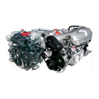
STEYR MO144M38 Manuals
Manuals and User Guides for STEYR MO144M38. We have
2
STEYR MO144M38 manuals available for free PDF download: Service Manual, Operation, Maintenance And Warranty Manual
STEYR MO144M38 Service Manual (331 pages)
MARINE ENGINES
Brand:
STEYR
| Category:
Engine
| Size: 27 MB
Table of Contents
Table of Contents
9
Z001019/0_6_July
4
Table of Contents
9
Engine
9
Ageneral Remarks
11
A 1 Model and Serial Numbers
11
A 2 Documentation
12
A 3 Model Summary
13
A 3.1 Model Summary 4 Cylinder Engines
13
A 3.2 Model Summary 6 Cylinder Engines
16
Technical Data and Overview
20
A 4.1 Technical Data and Overview 4 Cylinder Engines
20
A 4.2 Technical Data and Overview 6 Cylinder Engines
24
B Specifications
28
Fuel Requirements
28
B 2 Motor Oil
29
C Maintenance and Service
30
Trouble Check Chart
30
C2 Service- and Maintenance Schedule
32
General Information
34
Electronic Engine Management System (ECU)
34
Diagnostic System
35
D 3 Extended Storage Preservation Procedure
36
D 4 Engine Break-In Procedure
40
D 5 Operation after Break-In
42
E 1 Spare Parts Specification
44
E 2 Workshop Profile
44
E Quality Gudelines for Repair
44
E 3 Nomenclature
45
E 4 SI- System
46
E 5 Abbreviations
47
F 1 List of Operating Material
48
F Operating Material and Information on Disposal
48
F 2 Disposal of Automotive Waste Products
49
G 1 General Notes on Safety
50
G 2 Guidelines for Damage Prevention
50
G 3 Legal Rules
50
Gnotes on Safety
50
G 4 Safety in the Use of Operating Material
51
G 5 Measures in Case of Accidents
51
H 1 Listing of Thightening Torques
52
H Thightening Torques
52
General Tightening Torques
57
H 3 Testing of Torque Wrench
58
H 4 Non-Destructive Material Testing
58
H 5 Use of Adhesive and Sealing Materials
58
H 6 Solvent-Free Sealing Materials
58
J Wear Limits
60
J 1 Adjustment Information for Service and Maintenance
61
Table of Contents
63
Engine Timing, Engine Mount
65
Lock Crankshaft
65
Exchange Camshaft Housing Cover Sealing
68
Maintenance Timing-Belt Exchange
69
Remove Timing Belt
77
Timing Adjustment Procedure for Dismantled Engine
78
Replace Engine Mount and Engine Bracket
88
Cylinder Block
90
Replace Valves
90
Adjust Valve Clearance
92
Replace Valve Guide
92
Replace Pressure Regulating Valve for Oil Cooling Jet
93
Replace Stud Bolt for Unit Injector
94
Replace Dowel Pin for Positioning of Unit Injector
95
Replace Dowel Pin for Positioning of Camshaft Housing
96
Replace Coolant Supply Pipe
97
Replace External Screw Adaptor for Oil Cooler
97
Mount Frame Seal
98
Crankshaft, Bearing, Vibration Damper
100
Replace Crankshaft
100
Replace Gear for Oil Pump Drive
104
Flywheel, Housing
105
Replace Flywheel Housing
105
Coupling
106
Replace Flywheel
106
Replace Adapter Ring
107
Dismantle Piston and Connecting Rod
108
Piston and Connecting Rod
108
Camshaft, Housing, Valve Gear
110
Replace Camshaft Housing
110
Replace Valve Stem Gasket (on Engine Assembly)
114
Replace Control Rack
116
Replace Camshaft
118
Replace Rocker Arm Shaft
120
Replace Radial Shaft Seal of Camshaft
121
Replace Cam Follower
122
Replace Retainer of Cam Follower
123
Replace Valve Adjusting Element
124
Engine Housing, Oil Pump, Oil Suction Pipe
125
Replace Engine Housing
125
Replace Support Ring Rear
132
Replace Rear Radialshaft Sealing Ring
133
Replace Oil Pump (Front Ring Carrier)
134
Replace Oil Suction Pipe
135
Assembly of Intercooler
136
Intercooler
136
Remove Intercooler
136
Replace Intercooler - Element
141
Auxiliary Drive, in Front (PTO)
143
Engine Oil Cooler
144
Replace Engine Oil Cooler
144
Repair Oil Cooler
146
Change Motor Oil
147
Change Oil Filter
148
Exhaust Manifold, Seals, Heat Exchanger
149
Table of Contents
157
Fuel System / Functional Description
158
Fuel Pump, Unit Injector, Lines
160
Replace Fuel Pump
160
Disassembly and Assembly of Unit Injector
163
Fix Control Rack
170
Adjust Control Link (Injection Quantity)
171
Loosen Fixing of Control Rod
172
Adjust Start of Injection
173
Exchange Check Valve for Fuel Pre-Pressure to Unit Injector
176
Change Air Filter
177
Replace Turbocharger
178
Air Filter
177
Turbocharger
178
Check Bearing Clearance
181
Control Solenoid
182
Remove Control Solenoid
182
Install Control Solenoid
184
Replace Sensor, Indication of Control Rack Position
185
Change Fuel Filter
186
Replace Glow Plug
187
Measurement of Compression Pressure
188
Fuel System Check
190
Manual Injection Test Methode
190
Disengagement Methode of Injection
192
Air Bubble Formation in Fuel System
193
Exhaust System
195
Cooling System
199
Functional Description Cooling Circuit
200
Raw Water Circuit (External Cooling Circuit)
200
Closed Coolant from Cooling Circuit (Internal Engine Cooling Circuit)
202
Error Detection Cooling System
204
Check Points for Problems in Cooling System
207
Component Check Raw Water System
208
Drain the Coolant System
211
Fill the Cooling System
213
Coolant Tank
214
Cooler, Heat Exchanger, Expansion Tank
214
Disassembly Exhaust Manifold - Heat Exchanger
215
Checks
219
Exchange Heat Exchanger Element
221
Assembly of Exhaust Manifold
222
Exchange Additional Oil Cooler (Only Type 246)
224
Exchange Tandem Cooler
224
Coolant Pipes and Hoses
225
Exchange Triple Cooler
225
Pipes, Thermostat
225
Exchange Thermostat
226
Exchange Sacrificial Anodes
228
Coolant Pump
229
Exchange Coolant Pump
229
Install Coolant Pump
230
Exchange Poly-V-Belt
231
Poly-V-Belt
231
Exchange V-Belts
232
V-Belt
232
Adjust V-Belts
234
Exchange Raw Water Pump
235
Raw Water Pump
235
Check Closed Engine Cooling System for Air
236
Checks
236
Table of Contents
237
Alternator
240
Adjust Poly-V-Belt Tension
240
Technical Data of Alternator
242
Check Alternator (Error Detection for BOSCH Alternator, 4 Cyl. Engines)
250
Replace Starter Motor
252
Check Starter
253
Battery Cable Lengths and Cross-Sections
255
Cables, Wiring Harness - General
255
E - Box Base Plate; to Eng.no.: 482 17 000
256
Components of E - Box
257
Connection Relay Socket for K24, K26-1, K26-2 and K27
257
Connection Start Assist Relay K28
257
Wiring Harness; to Eng.no.: 482 17 000
258
E - Box Base Plate; from Eng.no.: 482 18 000/682 18 000 + SOLAS
264
Components of E - Box
265
Connection Relay Socket for K24, K26-1 and K27
265
Wiring Harness; from Eng.no.: 482 18 000/682 18 000 + SOLAS
266
Electronic Engine Management System
272
Electronics - General
272
Diagnostic System
273
Reading Error Codes
274
Principle Failure Code List
276
Replace Fuses
278
Connection J
279
Connection A5 and X5
280
Fitting Main Connector "J1" Properly
281
Instrument Panel
282
Chart - Error Indication on Instrument Panel
284
Instrument Panel (for SOLAS Only)
288
Used - Old Version
294
Cyl. Wiring Harness Instrument Panel (if Alternator "PRESTOLITE" Is Used - Old Version)
295
Description - Wiring Harness Instrument Panels 4/6 Cyl. Marine Engines (Current Version)
298
Adjust Instruments
304
Tachometer with Running-Time Meter
304
General Notes on Safety
306
Replace Instruments
306
Audible Warner, H22
308
Circuit Diagram Oil Pressure Gauge (Optional, Sensor B19-Gauge P2)
309
Circuit Diagram Voltmeter (Optional)
309
Potentiometer Accelerator, B13
310
Voltage Regulator 24V-12V Equalizer
311
DC-DC Converter
312
Component Configuration 4 Cyl. Engine
314
Component Configuration 6 Cyl. Engine
316
Calibration of Rack Position
318
Potentiometer Accelerator B13
320
Check Rack Position Feedback Sensor B14 (= Connector X14)
321
Check Sensors and Switches
321
Check Throttle Potentiometer B13 (Accelerator) (= Connector X13)
323
Check Speed Sensor B15 And/Or Wiring
325
Check Oil Pressure Sensor B18 And/Or Wiring
326
Check Oil Pressure Sensor "VDO-Instrument" (Option B19)
327
Check Coolant Temperature Sensor, B16
328
Check Audible Warner
329
Battery
330
Electrical Equipment
330
Advertisement
STEYR MO144M38 Operation, Maintenance And Warranty Manual (118 pages)
4/6 CYLINDERS MARINE ENGINES
Brand:
STEYR
| Category:
Engine
| Size: 11 MB
Table of Contents
Table of Contents
5
Start-Up and Functions
4
Fuel and Lubricants
4
Table of Contents
5
General
6
Marine Engine Overview
7
Product References, Illustrations and Specifications
8
Insurance
8
Stolen Unit
8
Owner Identification Card
8
Installation and Pre-Delivery Inspection Log
9
Dealer Service - Maintenance
9
Illustration Symbols
9
Repair Service
10
Replacement Parts
10
Before Casting off
10
Engine Submersion
11
Bottom Painting
11
Boat Bottom
11
Boating Responsibilities
12
Safety
12
Symbols
13
Table of Contents
15
Before Starting
17
Starting the Engine
18
Stopping the Engine
18
Starting the Engine (for SOLAS Only)
19
Stopping the Engine (for SOLAS Only)
19
Definitions
20
Procedure, Work Steps
20
Run in Procedure after Major Overhaul
20
Engine Break-In Procedure
21
Final Ten Hours of Break-In
21
First Ten Hours
21
Operation after Break-In
22
Shifting
23
Remote Control Operating Instructions
24
Fuel Economy
25
Gear Box - Information
25
High Altitude Operation
25
How to Shift and Control Speed
25
Instrument Panel
26
Instrument Panel, Standard
26
Instrument Indication During Normal Operation
27
Instrument Panel (for SOLAS Only)
28
Instrument Indication During Normal Operation (for SOLAS Only)
29
Emergency Cut off Switch (Lanyard)
30
Warning Lights and Audible Alarm
31
Electronic Engine Control Unit (ECU)
32
Diagnostic System
33
Optional Propellers
34
Propellers
34
Twin Installations
34
Operating Procedure for Freezing Temperatures
35
Propeller Care
35
Propeller Torque
35
Salt Water Operation
35
Water Jet
35
Fuel Contamination
36
Fuel Pump
36
Fuel System Checks
36
Cooling System (Function Description)
37
Alternator
38
Battery
38
Electrical Equipment
38
Circuit Breakers
39
Dry Operation
40
Instrument Panel
40
Interrupt Crankshaft Housing Ventilation
40
Inversion Switch
40
Table of Contents
41
Fuel Requirements
42
Fuel Selection Chart
42
How to Select Fuel
42
Engine Lubrication
43
Motor Oil
43
Oil Identification Symbol
43
Disposal of Automotive Waste Products
44
Table of Contents
45
Model and Serial Numbers
47
Technical Data and Overview MO54NA33
48
Technical Data and Overview MO84K32, MO94K33, MO114K33
50
Technical Data and Overview MO144M38, MO164M40, MO174V40
52
Technical Data and Overview MO196K35, MO236K42
54
Technical Data and Overview MO256K43, MO256H45
56
Technical Data and Overview MO286H43, MO126K25, MO156K25
58
Technical Data and Overview MO306H43WJ
60
Table of Contents
63
Foreword
65
Important Note
65
Owner Service Log
65
Service- and Maintenance Schedule
66
Maintenance Log
68
Table – Error Indication on Instrument Panel
70
Table – Error Indication on Instrument Panel (for Solas Only)
72
Reading Service Codes
74
Indication and Cancellation of Memorised Sensor and Circuit Faults
75
Selection and Clearing of Stored Service Codes
75
Principle Service Code List
76
Trouble Check Chart
78
Wiring Harness
80
Wiring Diagram/Marine Base - 4/6 Cylinder - 12 V
81
Wiring Diagram/Marine - 4/6 Cylinder - 2-Pole - 12 V (Option)
82
Wiring Diagram/Marine - 4/6 Cylinder - 24 V (Option)
83
Wiring Diagram/Marine - 4/6 Cylinder - 2-Pole - 24 V - Complete System
84
Description - Wiring Harness Instrument Panels 4/6 Cyl. Marine Engines (Current Version)
85
Wiring Diagram/Instrument Can Panel - 4/6 Cylinder - 12 V
86
Wiring Diagram/Instrument Can Panel - 4/6 Cylinder - 24 V (Option)
87
WIRING DIAGRAM/INSTRUMENT CAN PANEL - 4/6 CYLINDER - Solas - 12 V (OPTION)
88
Table of Contents
89
Check Motor Oil Level
91
Oil Level for Power Steering
91
Oil Level for Transmission
91
Refill Motor Oil
91
Check Coolant (Closed Cooling Circuit)
92
Check Raw Water (Open Circuit with Pump)
92
Drain the Raw Water Circuit of the Engine
92
Anti-Corrosion Anodes
93
Cooling System Anodes
93
Air Filter
94
Engine Alignment
94
Maintainance Poly-V-Belt Resp. Serpentine Belt
94
Adjustment of Belts
95
Alternator Belt
95
Belt for Raw Water Pump
95
Measuring Device VR00515/0 for Toothed- and V-Belt
95
Servopump Belt (if So)
95
Propeller Selection
97
STEYR MOTORS - Dealer - Check-List
98
Commissioning REPORT
100
Preparations for Off-Season Storage
102
Start-Up after Storage
102
Engine Log
103
Limited Engine Warranty
108
What You Must Do to Activate the Warranty
108
Extended Major Components Warranty
110
Summary of Warranty Coverage
111
Warranty Coverage for Genuine Spare Parts
111
Conditions of Warranty Coverage
111
Limitations and Exclusions
112
Procedure for Making a Warranty Claim
113
Venue and Applicable Law
114
If You Do Not Receive Satisfactory Warranty Service
114
Engine, Gearbox, Boat Model and Hull Identification Numbers
115
Steyr Owner Identification Card
116
Service Network
117
Advertisement
Related Products
STEYR MO144V38
STEYR MO126K25
STEYR MO196K35
STEYR MO156K25
STEYR MO114K33
STEYR MO164M40
STEYR MO126M28
STEYR MO166K28
STEYR MO174V40
STEYR MO94K33
STEYR Categories
Engine
Repeater
More STEYR Manuals
Login
Sign In
OR
Sign in with Facebook
Sign in with Google
Upload manual
Upload from disk
Upload from URL