Sign In
Upload
Manuals
Brands
ST Manuals
Motherboard
STM32429I-EVAL
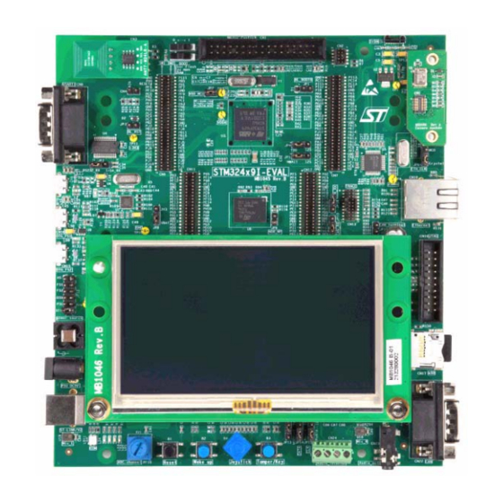
ST STM32429I-EVAL Manuals
Manuals and User Guides for ST STM32429I-EVAL. We have
2
ST STM32429I-EVAL manuals available for free PDF download: User Manual
ST STM32429I-EVAL User Manual (69 pages)
Brand:
ST
| Category:
Motherboard
| Size: 2 MB
Table of Contents
Table of Contents
2
1 Overview
6
Features
6
Demonstration Software
6
Order Code
7
Delivery Recommendations
7
2 Hardware Layout and Configuration
8
Figure 2. Hardware Block Diagram
8
Figure 3. Evaluation Board Layout
9
Development and Debug Support
10
Table 1. Third-Party Toolchains
10
Power Supply
11
Table 2. Power Related Jumpers
11
Clock Source
13
Reset Source
13
Table 3. 32.786 Khz Crystal X1 Related Solder Bridges
13
Table 4. 25 Mhz Crystal X2 Related Solder Bridges
13
Audio
14
Boot Option
14
Table 5. Boot Related Switches
14
Table 6. Audio Related Jumpers
15
Usb Otg1 Fs
15
Figure 1. STM32429I-EVAL Evaluation Board
16
RS-232 & Irda
16
Table 7. USB OTG2 Configuration
16
Table 8. RS-232 & Irda Related Jumper
16
Usb Otg2 Hs & Fs
16
Can
17
Microsd Card
17
Rf Eeprom
17
Table 9. CAN Related Jumpers
17
Ethernet
18
Extension Connector
18
Table 10. Ethernet Related Jumper
18
Table 11. Ethernet Related Solder Bridges
18
Analog Input
19
Camera Module
19
Memories
19
Table 12. nor Flash Related Jumpers
19
Display and Input Devices
20
Table 13. LCD Modules Connector (CN20)
20
Figure 4. Orientation Setting of 4.3 Inch LCD Daughterboard
21
Motor Control
21
Figure 5. PCB Underside Rework for Motor Control
22
Figure 6. PCB Topside Rework for Motor Control
22
Table 14. Motor Control Related Solder Bridges
22
3 Connectors
23
Motor Control Connector CN1
23
Table 15. Motor Control Connector CN1
23
Figure 7. Motor Control Connector CN1 (Top View)
23
Extension Connector CN2
24
Table 16. Extension Connector CN2
24
Figure 8. Extension Connector CN2 Top View
24
RF EEPROM Daughterboard Connector CN3
25
Analog Input Connector CN4
25
Table 17. RF EEPROM Daughterboard Connector CN3
25
Table 18. Analog Input-Output Connector CN4
25
Figure 9. RF EEPROM Daughterboard Connector CN3 (Front View)
25
Figure 10. Analog Input-Output Connector CN4 (Top View)
25
Camera Module Connector CN5
26
Table 19. Camera Module Connector CN5
26
Figure 11. Camera Module Connector CN5 (Top View)
26
Daughterboard Extension Connector CN6 and CN7
27
Table 20. Daughterboard Extension Connector CN6
27
Table 21. Daughterboard Extension Connector CN7
29
RS-232 Connector CN8
32
USB OTG2 HS Micro-AB Connector CN9
32
Table 22. RS-232 Connector CN8 with ISP Support
32
Table 23. USB OTG HS Micro-AB Connector CN9
32
Figure 12. RS-232 Connector (Front View)
32
Figure 13. USB OTG2 HS Micro-AB Connector CN9 (Front View)
32
Ethernet RJ45 Connector CN10
33
Memory Connectors CN11 and CN12
33
Table 24. RJ45 Connector CN10
33
Figure 14. Ethernet RJ45 Connector CN10 (Front View)
33
Table 25. Memory Connector CN11
34
Table 26. Memory Connector CN12
35
ETM Trace Debugging Connector CN13
37
USB OTG1 FS Micro-AB Connector CN14
37
Table 27. ETM Trace Debugging Connector CN13
37
Table 28. USB OTG1 FS Micro-AB Connector CN14
37
Figure 15. ETM Trace Debugging Connector CN13 (Top View)
37
Figure 16. USB OTG1 FS Micro-AB Connector CN14 (Front View)
37
USB OTG2 FS Micro-AB Connector CN15
38
JTAG/SWD Connector CN16
38
Table 29. USB OTG2 FS Micro-AB Connector CN15
38
Table 30. JTAG/SWD Debugging Connector CN15
38
Figure 17. USB OTG2 FS Micro-AB Connector CN15 (Front View)
38
Figure 18. JTAG/SWD Debugging Connector CN16 (Top View)
38
Microsd Connector CN17
39
Power Connector CN18
39
Table 31. Microsd Connector CN17
39
Figure 19. Microsd Connector CN17 (Top View)
39
Figure 20. Power Supply Connector CN18 (Front View)
39
ST-LINK/V2 Programming Connector CN19
40
TFT LCD Connector CN20
40
ST-LINK/V2 USB Type B Connector CN21
40
CAN D-Type 9-Pin Male Connector CN22
40
Table 32. USB Type B Connector CN21
40
Table 33. CAN D-Type 9-Pin Male Connector CN22
40
Figure 21. USB Type B Connector CN21 (Front View)
40
Figure 22. CAN D-Type 9-Pin Male Connector CN22 (Front View)
40
Audio Jack CN23
41
Audio Terminal CN24
41
ST-LINK/V2 Programming Tag-Connector CN25
41
Table 34. Audio Terminal CN24
41
Figure 23. Audio Terminal CN24 (Front View)
41
Schematics
42
Figure 24. STM324291-EVAL
42
Figure 25. MCU
43
Figure 26. Power
44
Figure 27. SRAM, Flash and SDRAM
45
Figure 28. Audio
46
Figure 29. LCD, Camera and Connectors
47
Figure 30. Ethernet
48
Figure 31. USB OTG HS
49
Figure 32. USB OTG FS
50
Figure 33. RS-232 and Irda
51
Figure 34. CAN, Microsd Card and IO Expander
52
Figure 35. Peripherals
53
Figure 36. Motor Control
54
Figure 37. Extension Connector
55
Figure 38. ST-LINK/V2
56
Figure 39. JTAG and Trace
57
Figure 40. 4.3' TFT LCD Daughter Board MB1046
58
Figure 41. Camera Daughter Board MB1066
59
Appendix A STM32429I-EVAL I/O Assignment
60
Table 35. STM32429I-EVAL I/O Assignment
60
Appendix B Mechanical Dimensions
67
Table 36. Mechanical Dimensions
67
Figure 42. Mechanical Dimensions
67
Revision History
68
Table 37. Document Revision History
68
Advertisement
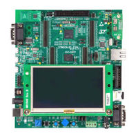
ST STM32429I-EVAL User Manual (59 pages)
evaluation board for STM32F429 MCUs
Brand:
ST
| Category:
Motherboard
| Size: 1 MB
Table of Contents
Table of Contents
2
Features
7
Ordering Information
8
Codification
8
Table 1. Ordering Information
8
Table 2. Codification Explanation
8
Development Environment
9
System Requirements
9
Development Toolchains
9
Demonstration Software
9
Delivery Recommendations
9
Hardware Layout and Configuration
10
Figure 2. Hardware Block Diagram
10
Figure 3. Evaluation Board Layout
11
Development and Debug Support
12
Power Supply
13
Table 3. Power Related Jumpers
13
Clock Source
15
Reset Source
15
Table 4. 32.786 Khz Crystal X1 Related Solder Bridges
15
Table 5. 25 Mhz Crystal X2 Related Solder Bridges
15
Boot Option
16
Audio
16
Table 6. Boot Related Switches
16
Usb Otg1 Fs
17
Table 7. Audio Related Jumpers
17
USB OTG2 HS and FS
18
RS-232 and Irda
18
Table 8. USB OTG2 Configuration
18
Table 9. RS-232 and Irda Related Jumper
18
Microsd™ Card
19
Rf-Eeprom
19
Can
19
Table 10. CAN Related Jumpers
19
Ethernet
20
Extension Connector
20
Table 11. Ethernet Related Jumper
20
Table 12. Ethernet Related Solder Bridges
20
Memories
21
Analog Input
21
Camera Module
21
Table 13. nor Flash Memory Related Jumpers
21
Display and Input Devices
22
Table 14. LCD Modules Connector (CN20)
22
Motor Control
23
Figure 4. Orientation Setting of 4.3 Inch LCD Daughterboard
23
Figure 5. PCB Underside Rework for Motor Control
24
Figure 6. PCB Topside Rework for Motor Control
24
Table 15. Motor Control Related Solder Bridges
25
Connectors
26
Motor Control Connector CN1
26
Table 16. Motor Control Connector CN1
26
Figure 7. Motor Control Connector CN1
26
Extension Connector CN2
27
Table 17. Extension Connector CN2
27
Figure 8. Extension Connector CN2 Top View
27
RF-EEPROM Daughterboard Connector CN3
28
Analog Input Connector CN4
28
Table 18. RF-EEPROM Daughterboard Connector CN3
28
Table 19. Analog Input-Output Connector CN4
28
Figure 9. RF-EEPROM Daughterboard Connector CN3 (Front View)
28
Figure 10. Analog Input-Output Connector CN4 (Top View)
28
Camera Module Connector CN5
29
Table 20. Camera Module Connector CN5
29
Figure 11. Camera Module Connector CN5 (Top View)
29
Daughterboard Extension Connector CN6 and CN7
30
Table 21. Daughterboard Extension Connector CN6
30
Table 22. Daughterboard Extension Connector CN7
32
RS-232 Connector CN8
35
USB OTG2 HS Micro-AB Connector CN9
35
Table 23. RS-232 Connector CN8 with ISP Support
35
Table 24. USB OTG HS Micro-AB Connector CN9
35
Figure 12. RS-232 Connector (Front View)
35
Figure 13. USB OTG2 HS Micro-AB Connector CN9 (Front View)
35
Ethernet RJ45 Connector CN10
36
Memory Connectors CN11 and CN12
36
Table 25. RJ45 Connector CN10
36
Table 26. Memory Connector CN11
36
Figure 14. Ethernet RJ45 Connector CN10 (Front View)
36
Table 27. Memory Connector CN12
38
ETM Trace Debugging Connector CN13
39
Table 28. ETM Trace Debugging Connector CN13
39
Figure 15. ETM Trace Debugging Connector CN13 (Top View)
39
USB OTG1 FS Micro-AB Connector CN14
40
USB OTG2 FS Micro-AB Connector CN15
40
Table 29. USB OTG1 FS Micro-AB Connector CN14
40
Table 30. USB OTG2 FS Micro-AB Connector CN15
40
Figure 16. USB OTG1 FS Micro-AB Connector CN14 (Front View)
40
Figure 17. USB OTG2 FS Micro-AB Connector CN15 (Front View)
40
JTAG/SWD Connector CN16
41
Microsd™ Connector CN17
41
Table 31. JTAG/SWD Debugging Connector CN15
41
Figure 18. JTAG/SWD Debugging Connector CN16 (Top View)
41
Figure 19. Microsd™ Connector CN17 (Front View)
41
Power Connector CN18
42
ST-LINK/V2 Programming Connector CN19
42
TFT LCD Connector CN20
42
Table 32. Microsd™ Connector CN17
42
Figure 20. Power Supply Connector CN18
42
ST-LINK/V2 USB Type B Connector CN21
43
CAN D-Type 9-Pin Male Connector CN22
43
Audio Jack CN23
43
Table 33. USB Type B Connector CN21
43
Table 34. CAN D-Type 9-Pin Male Connector CN22
43
Figure 21. USB Type B Connector CN21 (Front View)
43
Figure 22. CAN D-Type 9-Pin Male Connector CN22 (Front View)
43
Audio Terminal CN24
44
ST-LINK/V2 Programming Tag-Connector CN25
44
Table 35. Audio Terminal CN24
44
Figure 23. Audio Terminal CN24 (Front View)
44
STM32429I-EVAL Evaluation Board Information
45
Product Marking
45
STM32429I-EVAL Product History
46
Product Identification STM32429I-EVAL1
46
Product Identification VA32F429I$AX1
46
Board Revision History
46
Mb1045
46
Mb1046
46
Mb1066
46
Mb1020
46
Figure 1. STM32429I-EVAL Evaluation Board
46
Board Known Limitations
47
Mb1045
47
Mb1046
47
Mb1066
47
Mb1020
47
Appendix A STM32429I-EVAL I/O Assignment
48
Table 36. STM32429I-EVAL I/O Assignment
48
Appendix B Mechanical Dimensions
55
Table 37. Mechanical Dimensions
55
Figure 24. Mechanical Dimensions
55
Appendix C Federal Communications Commission (FCC)
56
And ISED Canada Compliance Statements
56
FCC Compliance Statement
56
ISED Compliance Statement
56
Appendix Dce Conformity
57
Revision History
58
Table 38. Document Revision History
58
Advertisement
Related Products
ST STM3240G-EVAL
ST STM32479I-EVAL
ST STM3241G-EVAL
ST STM32439I-EVAL
ST STM32429I-EVAL1
ST STM32F779I-EVAL
ST STM32F207IFT6
ST STM32091C-EVAL
ST STM32L152VBT6
ST STM32MP157D-EV1
ST Categories
Motherboard
Computer Hardware
Microcontrollers
Control Unit
Controller
More ST Manuals
Login
Sign In
OR
Sign in with Facebook
Sign in with Google
Upload manual
Upload from disk
Upload from URL