Sign In
Upload
Manuals
Brands
ST Manuals
Motherboard
STM3240G-EVAL
ST STM3240G-EVAL Manuals
Manuals and User Guides for ST STM3240G-EVAL. We have
3
ST STM3240G-EVAL manuals available for free PDF download: User Manual
ST STM3240G-EVAL User Manual (67 pages)
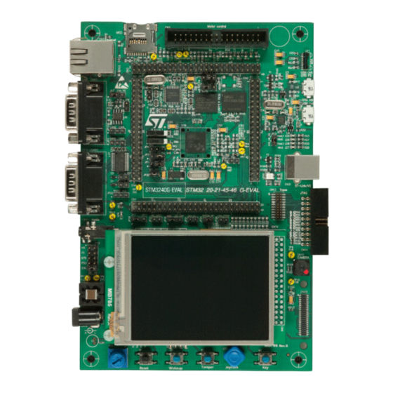
STM3240G-EVAL evaluation board UM1461
Brand:
ST
| Category:
Motherboard
| Size: 4 MB
Table of Contents
Figure 1. STM3240G-EVAL Evaluation Board
1
Table of Contents
2
List of Figures
5
Overview
6
Features
6
Demonstration Software
6
Order Code
6
Delivery Recommendations
7
Hardware Layout and Configuration
8
Figure 2. Hardware Layout and Configuration
9
Figure 3. STM3240G-EVAL Evaluation Board Layout
10
Figure 4. Hardware Layout and Configuration
10
Figure 5. STM3240G-EVAL Evaluation Board Layout
10
Power Supply
11
Table 1. Power Related Jumpers and Solder Bridges
11
Boot Option
12
Table 2. Boot Related Jumpers
12
Clock Source
13
Reset Source
13
Audio
13
Table 3. Audio Related Jumpers
13
Eeprom
14
Can
14
Table 4. EEPROM Related Jumper and Solder Bridge
14
Table 5. CAN-Related Jumpers
14
RS-232 and Irda
15
Table 6. RS-232 and Irda Related Jumper
15
Motor Control
16
Table 7. Motor Control Solder Bridges
16
Smartcard
17
Microsd Card
17
Table 8. Connection between ST8024 and STM32F407IGH6
17
Table 9. Smartcard Related Jumper
17
Table 10. Microsd Card Related Jumpers
17
Mems
18
Potentiometer
18
Adc
18
Usb-Otg Fs
18
Ethernet
18
Table 11. Ethernet Related Jumpers and Solder Bridges
18
Usb-Otg Hs
19
Table 12. Microsd Card Related Jumper
19
Camera Module
20
Table 13. Camera Module Related Jumpers
20
Figure 6. Pin 1 Camera Plug
20
Sram
21
Development and Debug Support
21
Table 14. SRAM Related Jumpers
21
Table 15. Third-Party Toolchain Support
21
Display and Input Devices
23
Table 16. LCD Modules
23
Connectors
24
Daughterboard Extension Connectors CN1, 2, 3 and 4
24
Table 17. Daughterboard Extension Connector CN1
24
Table 18. Daughterboard Extension Connector CN2
26
Table 19. Daughterboard Extension Connector CN3
27
Table 20. Daughterboard Extension Connector CN4
29
Figure 7. Motor Control Connector CN5
31
Motor Control Connector CN5
31
Table 21. Motor Control Connector CN5
31
Ethernet RJ45 Connector CN7
32
Figure 8. Microsd Connector CN6
32
Figure 9. Ethernet RJ45 Connector CN7
32
Microsd Connector CN6
32
Table 22. Microsd Connector CN6
32
Table 23. RJ45 Connector CN7
32
Figure 10. USB-OTG FS Micro-AB Connector CN8
33
Figure 11. USB-OTG HS Micro-AB Connector CN9
33
Table 24. USB-OTG FS Micro-AB Connector CN8
33
Table 25. USB-OTG HS Micro-AB Connector CN9
33
USB-OTG FS Micro-AB Connector CN8
33
USB-OTG HS Micro-AB Connector CN9
33
Audio Connector CN11
34
CAN D-Type 9-Pin Male Connectors CN10 (CAN1 or CAN2)
34
Figure 12. CAN D-Type 9-Pin Male Connector CN10 (CAN1 or CAN2)
34
Figure 13. Trace Debugging Connector CN13
34
Table 26. CAN D-Type 9-Pin Male Connector CN10 (CAN1 or CAN2)
34
Table 27. Trace Debugging Connector CN13
34
Trace Debugging Connector CN13
34
Camera Module Connector CN15
35
Figure 14. JTAG Debugging Connector CN14
35
Figure 15. Camera Module Connector CN15 (Front View)
35
JTAG Debugging Connector CN14
35
Table 28. JTAG Debugging Connector CN14
35
Table 29. Camera Module Connector CN15
35
Figure 16. RS-232 Connector CN16 with ISP Support (Front View)
36
Figure 17. Power Supply Connector CN18
36
Power Connector CN18
36
RS-232 Connector CN16
36
Table 30. RS-232 Connector CN16 with ISP Support
36
Figure 18. Smartcard Connector CN20
37
Smartcard Connector CN20
37
ST-LINK/V2 Connector CN21
37
Table 31. Smartcard Connector CN20
37
TFT LCD Connector CN19
37
Camera Extension Connector CN23
38
STM3240G-EVAL Pinout
38
Table 32. Camera Extension Connector CN23
38
Table 33. STM3240G-EVAL Pinout
43
Schematics
44
Figure 19. STM3240G-EVAL
45
Figure 20. MCU
46
Figure 21. USB-OTG HS
47
Figure 22. Camera
48
Figure 23. Ethernet
49
Figure 24. Audio
50
Figure 25. USB-OTG FS
51
Figure 26. SRAM
52
Figure 27. LCD
53
Figure 28. RS-232 and Irda
54
Figure 29. CAN
55
Figure 30. I/O Peripherals
56
Figure 31. I/O Expandor
57
Figure 32. Microsd Card
58
Figure 33. Motor Control
59
Figure 34. Smartcard
60
Figure 35. JTAG and Trace
61
Figure 36. Power
62
Figure 37. Extension Connector
63
Figure 38. STLINK/V2
64
Figure 39. 3.2" LCD Module with SPI and 16-Bit Interface
65
Revision History
66
Table 34. Document Revision History
66
Advertisement
ST STM3240G-EVAL User Manual (67 pages)
Brand:
ST
| Category:
Motherboard
| Size: 1 MB
Table of Contents
Table of Contents
2
Overview
6
Features
6
Demonstration Software
6
Ordering Information
7
Delivery Recommendations
7
Hardware Layout and Configuration
7
Table 1. Ordering Information
7
Figure 2. Hardware Layout and Configuration
8
Figure 3. STM3240G-EVAL Evaluation Board Layout
9
Power Supply
10
Table 2. Power Related Jumpers and Solder Bridges
10
Boot Option
11
Table 3. Boot Related Jumpers
11
Clock Source
12
Reset Source
12
Audio
12
Eeprom
13
Can
13
Table 4. Audio Related Jumpers
13
Table 5. EEPROM Related Jumper and Solder Bridge
13
Table 6. CAN-Related Jumpers
13
Table 7. RS-232 and Irda Related Jumper
14
Motor Control
15
Table 8. Motor Control Solder Bridges
15
RS-232 and Irda
16
Smartcard
16
Microsd Card
16
Table 9. Connection between ST8024 and STM32F407IGH6
16
Table 10. Smartcard Related Jumper
16
Table 11. Microsd Card Related Jumpers
16
St Mems
17
Potentiometer
17
Adc
17
Usb-Otg Fs
17
Ethernet
17
Table 12. Ethernet Related Jumpers and Solder Bridges
17
Usb-Otg Hs
18
Table 13. Microsd Card Related Jumper
18
Camera Module
19
Table 14. Camera Module Related Jumpers
19
Figure 4. Pin 1 Camera Plug
19
Sram
20
Development and Debug Support
20
Table 15. SRAM Related Jumpers
20
Table 16. Third-Party Toolchain Support
20
Display and Input Devices
22
Table 17. LCD Modules
22
Connectors
23
Daughterboard Extension Connectors CN1, 2, 3 and 4
23
Table 18. Daughterboard Extension Connector CN1
23
Table 19. Daughterboard Extension Connector CN2
25
Table 20. Daughterboard Extension Connector CN3
26
Table 21. Daughterboard Extension Connector CN4
28
Figure 5. Motor Control Connector CN5
30
Motor Control Connector CN5
30
Table 22. Motor Control Connector CN5
30
Ethernet RJ45 Connector CN7
31
Figure 6. Microsd Connector CN6
31
Figure 7. Ethernet RJ45 Connector CN7
31
Microsd Connector CN6
31
Table 23. Microsd Connector CN6
31
Table 24. RJ45 Connector CN7
31
Figure 8. USB-OTG FS Micro-AB Connector CN8
32
Figure 9. USB-OTG HS Micro-AB Connector CN9
32
Table 25. USB-OTG FS Micro-AB Connector CN8
32
Table 26. USB-OTG HS Micro-AB Connector CN9
32
USB-OTG FS Micro-AB Connector CN8
32
USB-OTG HS Micro-AB Connector CN9
32
Audio Connector CN11
33
CAN D-Type 9-Pin Male Connectors CN10 (CAN1 or CAN2)
33
Figure 10. CAN D-Type 9-Pin Male Connector CN10 (CAN1 or CAN2)
33
Figure 11. Trace Debugging Connector CN13
33
Table 27. CAN D-Type 9-Pin Male Connector CN10 (CAN1 or CAN2)
33
Table 28. Trace Debugging Connector CN13
33
Trace Debugging Connector CN13
33
Figure 12. JTAG Debugging Connector CN14
34
JTAG Debugging Connector CN14
34
Table 29. JTAG Debugging Connector CN14
34
Camera Module Connector CN15
35
Figure 13. Camera Module Connector CN15 (Front View)
35
Figure 14. RS-232 Connector CN16 with ISP Support (Front View)
35
RS-232 Connector CN16
35
Table 30. Camera Module Connector CN15
35
Figure 15. Power Supply Connector CN18
36
Figure 16. Smartcard Connector CN20
36
Power Connector CN18
36
Smartcard Connector CN20
36
Table 31. RS-232 Connector CN16 with ISP Support
36
TFT LCD Connector CN19
36
ST-LINK/V2 Connector CN21
37
Table 32. Smartcard Connector CN20
37
Camera Extension Connector CN23
38
STM3240G-EVAL Pinout
38
Table 33. Camera Extension Connector CN23
38
Table 34. STM3240G-EVAL Pinout
38
Appendix A Schematics
44
Figure 17. STM3240G-EVAL
44
Figure 18. MCU
44
Figure 19. USB-OTG HS
44
Figure 20. Camera
44
Figure 21. Ethernet
44
Figure 22. Audio
44
Figure 23. USB-OTG FS
44
Figure 24. SRAM
44
Figure 25. LCD
44
Revision History
66
Table 35. Document Revision History
66
ST STM3240G-EVAL User Manual (65 pages)
Brand:
ST
| Category:
Motherboard
| Size: 2 MB
Table of Contents
Table of Contents
2
Overview
4
Features
4
Demonstration Software
4
Order Code
4
Delivery Recommendations
5
Hardware Layout and Configuration
6
Power Supply
9
Boot Option
10
Clock Source
11
Reset Source
11
Audio
11
Eeprom
11
Can
12
RS-232 and Irda
12
Motor Control
13
Smartcard
14
Microsd Card
15
Mems
15
Potentiometer
15
Adc
15
Usb Otg Fs
16
Ethernet
16
Usb Otg Hs
17
Camera Module
18
Sram
19
Development and Debug Support
20
Display and Input Devices
21
Connectors
22
Daughter Board Extension Connectors CN1, 2, 3 and 4
22
Motor Control Connector CN5
29
Microsd Connector CN6
30
Ethernet RJ45 Connector CN7
30
USB OTG HS Micro-AB Connector CN9
31
USB OTG FS Micro-AB Connector CN8
31
Audio Connector CN11
32
Trace Debugging Connector CN13
32
CAN D-Type 9-Pin Male Connectors CN10 (CAN1 or CAN2)
32
JTAG Debugging Connector CN14
33
Camera Module Connector CN15
33
RS-232 Connector CN16
34
Power Connector CN18
34
Camera Extension Connector CN23
35
TFT LCD Connector CN19
35
ST-LINK/V2 Connector CN21
35
Smartcard Connector CN20
35
STM3240G-EVAL Pinout
36
Schematics
42
Figure 17: STM3240G-EVAL
43
Figure 18: MCU
44
Figure 19: USB OTG HS
45
Figure 20: Camera
46
Figure 21: Ethernet
47
Figure 22: Audio
48
Figure 23: USB OTG FS
49
Figure 24: SRAM
50
Figure 25: LCD
51
Figure 27: CAN
53
Figure 28: I/O Peripherals
54
Figure 29: I/O Expandor
55
Figure 30: Microsd Card
56
Figure 31: Motor Control
57
Figure 32: Smartcard
58
Figure 33: JTAG and Trace
59
Figure 34: Power
60
Figure 35: Extension Connector
61
Figure 36: STLINK/V2
62
Figure 37: 3.2" LCD Module with SPI and 16-Bit Interface
63
Revision History
64
Advertisement
Advertisement
Related Products
ST STM32479I-EVAL
ST STM3241G-EVAL
ST STM32429I-EVAL
ST STM32439I-EVAL
ST STM32429I-EVAL1
ST STM32F401xD Series
ST STM32F469 Series
ST STM32G070RBT6
ST STM32CubeF4
ST STM32 NUCLEO-F070RB
ST Categories
Motherboard
Computer Hardware
Microcontrollers
Control Unit
Controller
More ST Manuals
Login
Sign In
OR
Sign in with Facebook
Sign in with Google
Upload manual
Upload from disk
Upload from URL