Sign In
Upload
Manuals
Brands
ST Manuals
Computer Hardware
STLINK-V3PWR
ST STLINK-V3PWR Manuals
Manuals and User Guides for ST STLINK-V3PWR. We have
1
ST STLINK-V3PWR manual available for free PDF download: User Manual
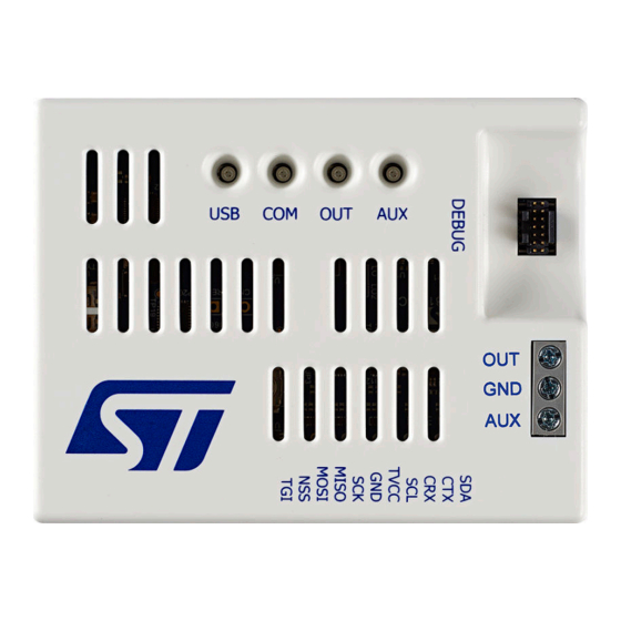
ST STLINK-V3PWR User Manual (30 pages)
Source measurement unit (SMU) and debugger/programmer for STM32 microcontrollers
Brand:
ST
| Category:
Computer Hardware
| Size: 1 MB
Table of Contents
Figure 1. STLINK-V3PWR Top, Bottom, and Cable Views
1
Features
2
Ordering Information
3
Table 1. Ordering Information
3
Development Environment
4
System Requirements
4
Development Toolchains
4
Toolchain Versions
4
Drivers and Firmware Upgrade
4
Table 2. Glossary
4
Glossary
5
Table 3. Glossary
5
Product Information
6
Product Content
6
STLINK-V3PWR Connectors and Leds Identification
6
USB Connection with a Host PC
7
Pre-Requisite
7
Detailed Description
7
Figure 2. STLINK-V3PWR Connections
7
Mechanical Information
8
Thermal Recommendation
8
Known Limitation
8
Table 4. USB Host PC or Hub Port Identification
8
Figure 3. Product Dimensions
8
Quick Start
9
Typical Application
9
Connection with a Target Application for Power Measurements
9
Recommendations for Power Measurements
9
Figure 4. STLINK-V3PWR Connection
9
Software Configuration
10
Figure 5. Stm32Cubemonitor-Power Setting
10
STLINK-V3PWR Functional Description
11
STLINK-V3PWR Overview
11
SMU Output (OUT)
11
Figure 6. STLINK-V3PWR Block Diagram
11
Figure 7. STLINK-V3PWR SMU Block Diagram
11
Voltage Source
12
Current Measurement
12
Figure 8. STLINK-V3PWR SMU Operating Area
12
Self-Calibration Management
13
Overcurrent and Short Circuit Management
13
Figure 9. SMU Current Measurement Ranges
13
Auxiliary Power Source Output (AUX)
14
Debugger Interfaces (SWD/JTAG/VCP)
14
Target Voltage Connection (T_VCC)
15
SWD with SWV
15
Jtag
15
Virtual COM Port (VCP)
15
Baud Rate Computing
15
Bridge Functions
16
Bridge SPI
16
Bridge I 2 C
16
Bridge CAN
16
Bridge Gpios
16
Leds Management
16
LED Management
16
Table 5. Leds Overview
16
Table 6. USB LED
16
Table 7. COM LED
17
Table 8. out LED
17
Table 9. VAUX LED
17
Electrical and Performance Parameters
18
Absolute Maximum Rating
18
Recommended Operating Conditions
18
SMU Output (OUT) Characteristics
18
SMU Voltage Source Characteristics
18
Table 10. Absolute Maximum Rating
18
Table 11. Recommended Operating Conditions
18
Table 12. SMU Voltage Source Characteristics
18
AUX Output (AUX) Voltage Source Characteristics
19
Table 13. Auxiliary Output (AUX) Voltage Source Characteristics
19
Debug and Bridge Performance
20
Table 14. Debug and Bridge Performances
20
Board Connectors Description
21
Conventions
21
Power (Out/Aux)
21
DEBUG (STM32 JTAG/SWD and VCP)
21
Table 15. I/O Type Definition
21
Table 16. Power Connector Pinout
21
Figure 10. POWER Connector (Front View)
21
Figure 11. DEBUG STDC14 Connector (Top View)
21
BRIDGE (I 2 C, CAN, SPI, UART, and GPIO)
22
Table 17. DEBUG STDC14 Connector Pinout
22
Table 18. BRIDGE Connector Pinout
22
Flat Ribbons
23
Table 19. ARM10/MIPI10-Compatible Connector Pinout (Target Side)
23
Table 20. ARM20/MIPI20-Compatible Connector Pinout (Target Side)
23
Federal Communications Commission (FCC) and ISED Canada Compliance
24
Statements
24
FCC Compliance Statement
24
ISED Compliance Statement
24
Revision History
25
Table 21. Document Revision History
25
Table of Contents
26
List of Tables
28
List of Figures
29
Advertisement
Advertisement
Related Products
ST STA309A
ST ST7MDTU3-EMU2B
ST ST8034T
ST STM32F078VB
ST STSW-L9961BMS
ST STM8SVLDISCOVERY
ST STM32L15 QC Series
ST STM32L151QC
ST STM32L151ZCT6
ST STM32F334C8
ST Categories
Motherboard
Computer Hardware
Microcontrollers
Control Unit
Controller
More ST Manuals
Login
Sign In
OR
Sign in with Facebook
Sign in with Google
Upload manual
Upload from disk
Upload from URL