Sign In
Upload
Manuals
Brands
ST Manuals
Microcontrollers
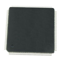
ST10F276Z5
ST ST10F276Z5 Manuals
Manuals and User Guides for ST ST10F276Z5. We have
1
ST ST10F276Z5 manual available for free PDF download: User Manual
ST ST10F276Z5 User Manual (564 pages)
High performance 16-bit microcontrollers
Brand:
ST
| Category:
Microcontrollers
| Size: 22 MB
Table of Contents
Table of Contents
2
Architectural Overview
22
Basic CPU Concepts and Optimization
22
Figure 1. St10F276X Functional Block Diagram
23
Figure 2. CPU Block Diagram
24
High Instruction Bandwidth / Fast Execution
24
Extended Bit Processing and Peripheral Control
25
High Function 8-Bit and 16-Bit ALU
25
High Performance Branch, Call and Loop Processing
25
Consistent and Optimized Instruction Formats
26
Programmable Multiple Priority Interrupt System
27
On-Chip System Resources
27
Peripheral Event Control and Interrupt Control
28
Memory Areas
28
External Bus Interface
29
Clock Generator
30
Figure 3. Clock Block Diagram
30
Direct Drive
31
PLL Operation
31
Prescaler Operation
31
Oscillator Watchdog (OWD)
32
On-Chip Peripheral Blocks
32
Peripheral Interfaces
33
Peripheral Timing
33
Programming Hints
33
Parallel Ports
34
Serial Channels
34
General Purpose Timer (GPT) Unit
35
Watchdog Timer
36
Capture / Compare (CAPCOM) Units
36
Pulse Width Modulation Unit
37
A/D Converter
37
CAN Module
38
I2C Serial Interface
38
Real Time Clock
38
Protected Bits
39
Table 1. Protected Bit
39
Memory Organization
40
Word, Byte and Bit Storage
41
Figure 4. ST10F276 Memory Mapping (User Mode: Flash Read Operation)
41
On-Chip Flash
42
Figure 5. Storage of Words, Bytes and Bits in a Byte Organized Memory
42
Table 2. Segment 8 Address Range Mapping
43
Table 3. 512 Kbyte Iflash Memory Block Organization
43
Table 4. 320 Kbyte Xflash Memory Block Organization
43
IRAM and SFR Area
44
Figure 6. On-Chip RAM and SFR/ESFR Areas
45
General Purpose Registers
46
System Stack
46
Table 5. Stack Size
46
PEC Source and Destination Pointers
47
Table 6. Mapping of General Purpose Registers to RAM Addresses
47
Figure 7. Location of the PEC Pointers
48
Special Function Registers
48
The On-Chip XRAM
49
XRAM Access Via External Masters
50
External Memory Space
50
Crossing Memory Boundaries
51
The Central Processing Unit (CPU)
52
Instruction Pipelines
54
Figure 8. CPU Block Diagram
54
Figure 9. Sequential Instruction Pipelining
55
Sequential Instruction Processing
55
Standard Branch Instruction Processing
55
Cache Jump Instruction Processing
56
Figure 10. Standard Branch Instruction Pipelining
56
Figure 11. Cache Jump Instruction Pipelining
56
Particular Pipeline Effects
56
Bit-Handling and Bit-Protection
59
Instruction Execution Times
60
CPU Special Function Registers
61
Table 7. Minimum Execution Times
61
The System Configuration Register SYSCON
62
Table 8. Stack Size
64
X-Peripherals Control Register (XPERCON)
65
XPERCON and XPEREMU Registers
66
Emulation Dedicated Registers
67
The Processor Status Word PSW
67
Table 9. Shift Right Rounding Error Evaluation
69
The Instruction Pointer IP
70
Figure 12. Addressing Via the Code Segment Pointer
71
The Code Segment Pointer CSP
71
The Data Page Pointers DPP0, DPP1, DPP2, DPP3
72
Figure 13. Addressing Via the Data Page Pointers
73
The Context Pointer CP
73
Figure 14. Register Bank Selection Via Register CP
75
Figure 15. Implicit CP Use by Short GPR Addressing Modes
75
The Stack Overflow Pointer STKOV
76
The Stack Pointer SP
76
The Stack Underflow Pointer STKUN
77
The Multiply / Divide High Register MDH
78
The Multiply / Divide Low Register MDL
78
The Constant Zeros Register ZEROS
79
The Multiply / Divide Control Register MDC
79
The Constant Ones Register ONES
81
Multiply-Accumulate Unit (MAC)
82
MAC Features
82
MAC Operation
83
Figure 16. MAC Architecture
83
Instruction Pipelining
84
Particular Pipeline Effects with the MAC Unit
84
Address Generation
85
Table 10. Pointer Post-Modification Combinations for IDXI and Rwn
85
16 X 16 Signed/Unsigned Parallel Multiplier
86
40-Bit Signed Arithmetic Unit
86
Figure 17. Example of Parallel Data Move
86
Table 11. Parallel Data Move Addressing
86
The 40-Bit Signed Accumulator Register
87
Data Limiter
88
Table 12. Limiter Output Using Costore Instruction
88
The 40-Bit Adder / Subtracter
88
Repeat Unit
89
The Accumulator Shifter
89
Figure 18. Pipeline Diagram for MAC Interrupt Response Time
90
MAC Interrupt
90
Number Representation & Rounding
90
MAC Register Set
91
Address Registers
91
Accumulator & Control Registers
91
MAC Instruction Set Summary
94
Table 13. MAC Register Address in Coreg Addressing Mode
94
Table 14. MAC Instruction Set Summary
94
Interrupt and Trap Functions
96
Interrupt System Structure
96
Table 15. Interrupt and PEC Service Request Sources
97
Table 16. Vector Locations and Status for Hardware Traps
99
Interrupt Control Registers
100
Interrupt System Register Description
100
Normal Interrupt Processing and PEC Service
100
Interrupt Priority Level and Group Level
101
Figure 19. Priority Levels and PEC Channels
102
Interrupt Control Functions in the PSW
103
Operation of the PEC Channels
104
Table 17. PEC Control Register Addresses
104
Prioritizing Interrupt & PEC Service Requests
106
Enabling and Disabling Interrupt Requests
106
Figure 20. Mapping of PEC Pointers into the IRAM
106
Interrupt Class Management
107
Table 18. Example of Software Controlled Interrupt Classes
107
Saving the Status During Interrupt Service
108
Context Switching
109
Figure 21. Task Status Saved on the System Stack
109
Interrupt Response Times
110
Figure 22. Pipeline Diagram for Interrupt Response Time
110
PEC Response Times
111
Figure 23. Pipeline Diagram for PEC Response Time
112
External Interrupts
113
Table 19. Pins to be Used as External Interrupt Inputs
114
Fast External Interrupts
115
X-Peripheral Interrupt
117
Table 20. X-Interrupt Detailed Mapping
118
Figure 24. X-Interrupt Basic Structure
118
Trap Functions
128
Table 21. Trap Priorities
128
Hardware Traps
129
Software Traps
129
External NMI Trap
131
Stack Overflow Trap
131
MAC Interrupt
132
Protection Fault Trap
132
Stack Underflow Trap
132
Undefined Opcode Trap
132
Illegal External Bus Access Trap
133
Illegal Instruction Access Trap
133
Illegal Word Operand Access Trap
133
Parallel Ports
134
Introduction
134
Open Drain Mode
134
Figure 25. Sfrs, XBUS Registers and Pins Associated with the Parallel Ports
136
Input Threshold Control
137
Figure 26. Output Drivers in Push-Pull Mode and in Open Drain Mode
137
Alternate Port Functions
138
Figure 27. Hysteresis Concept
138
Port0
139
Alternate Functions of PORT0
140
Figure 28. PORT0 I/O and Alternate Functions
141
Port1
142
Figure 29. Block Diagram of a PORT0 Pin
142
Alternate Functions of PORT1
143
Figure 30. PORT1 I/O and Alternate Functions
144
PORT1 Analog Inputs Disturb Protection
144
Figure 31. Block Diagram of Input Section of a P1L Pin
145
Port2
146
Figure 32. Block Diagram of a PORT1 Pin
146
Alternate Functions of Port2
147
External Interrupts
148
Figure 33. Port2 I/O and Alternate Functions
149
Table 22. Port2 Alternate Functions
149
Port3
150
Figure 34. Block Diagram of a Port2 Pin
150
Alternate Functions of Port3
151
Figure 35. Port3 I/O and Alternate Functions
152
Table 23. Port3 Alternative Functions
152
Figure 36. Block Diagram of a Port3 Pin
153
Port4
154
Figure 37. Block Diagram of P3.15 (CLKOUT) and P3.12 (BHE/WRH) Pins
154
Alternate Functions of Port4
155
Figure 38. Port4 I/O and Alternate Functions
156
Table 24. Port4 Alternate Functions
156
Figure 39. Block Diagram of Port4 Pins 3
157
Figure 40. Block Diagram of P4.4 Pin
158
Figure 41. Block Diagram of P4.5 Pin
159
Figure 42. Block Diagram of P4.6 Pin
160
Port5
161
Figure 43. Block Diagram of P4.7 Pin
161
Alternate Functions of Port5
162
Table 25. Port5 Alternate Functions
162
Figure 44. Port5 I/O and Alternate Functions
163
Figure 45. Block Diagram of a Port5 Pin
163
Port5 Analog Inputs Disturb Protection
163
Port6
164
Alternate Functions of Port6
165
Table 26. Port6 Alternate Functions
166
Figure 46. Port6 I/O and Alternate Functions
166
Figure 47. Block Diagram of Port6 Pins 4
167
Figure 48. Block Diagram of P6.5 Pin
168
Port7
169
Alternate Functions of Port7
169
Table 27. Port7 Alternate Functions
170
Figure 49. Port7 I/O and Alternate Functions
170
Figure 50. Block Diagram of Port7 Pins 3
171
Port8
172
Figure 51. Block Diagram of Port7 Pins 7
172
Alternate Functions of Port8
174
Figure 52. Port8 I/O and Alternate Functions
175
Table 28. Port8 Alternate Functions
175
Figure 53. Block Diagram of Port8 Pins 3
176
Figure 54. Block Diagram of P8.4 and P8.5 Pins
177
Figure 55. Block Diagram of P8.6 Pin
178
Dedicated Pins
179
Table 29. Summary of Dedicated Pins
179
Figure 56. RPD External RC Circuit
180
The External Bus Interface
181
Single Chip Mode
181
Figure 57. Sfrs and Port Pins Associated with the External Bus Interface
182
External Bus Modes
183
Multiplexed Bus Modes
183
De-Multiplexed Bus Modes
184
Figure 58. Multiplexed Bus Cycle
184
Switching between the Bus Modes
185
Figure 59. De-Multiplexed Bus Cycle
185
External Data Bus Width
186
Disable / Enable Control for Pin BHE (BYTDIS)
187
Segment Address Generation
187
Figure 60. Switching from De-Multiplexed to Multiplexed Bus Mode
187
CS Signal Generation
188
Segment Address Versus Chip Select
189
Programmable Bus Characteristics
190
ALE Length Control
190
Figure 61. Programmable External Bus Cycle
190
Programmable Memory Cycle Time
191
Figure 62. ALE Length Control
191
Programmable Memory Tri-State Time
192
Figure 63. Memory Cycle Time
192
Read / Write Signal Delay
193
Figure 64. Memory Tri-State Time
193
READY Polarity
194
READY / READY Controlled Bus Cycles
194
Figure 65. Read / Write Delay
194
Figure 66. READY/READY Controlled Bus Cycles
195
Programmable Chip Select Timing Control
196
Controlling the External Bus Controller
196
Figure 67. Chip Select Delay
196
Address Window Arbitration
201
Definition of Address Areas
201
Table 30. Definition of Address Areas
201
Figure 68. Address Window Arbitration
202
Precautions and Hints
203
EBC Idle State
203
Table 31. Status of the External Bus Interface During EBC Idle State
203
External Bus Arbitration
204
Connecting Bus Masters
204
Entering the Hold State
205
Figure 69. Sharing External Resources Using Slave Mode
205
Exiting the Hold State
206
Figure 70. External Bus Arbitration, Releasing the Bus
206
The XBUS Interface
207
Figure 71. External Bus Arbitration, (Regaining the Bus)
207
Table 32. Definition of XBUS Address Areas
208
Figure 72. Memory Mapping (User Mode: Flash Read Operations / XADRS = 800Bh)
210
Figure 73. Memory Mapping (User Mode: Flash Read Operations / XADRS = C00Ah)
211
EA Functionality
213
Figure 74. EA / VSTBY External Circuit
214
The General Purpose Timer Units
215
Timer Block GPT1
215
Figure 75. Sfrs and Port Pins Associated with Timer Block GPT1
216
Figure 76. GPT1 Block Diagram
217
GPT1 Core Timer T3
217
Table 33. GPT1 Core Timer T3 Count Direction Control
218
Figure 77. Core Timer T3 in Timer Mode
219
Table 34. GPT1 Timer Resolutions
220
Figure 78. Core Timer T3 in Gated Timer Mode
221
Figure 79. Core Timer T3 in Counter Mode
221
Table 35. GPT1 Core Timer T3 (Counter Mode) Input Edge Selection
221
Figure 80. Core Timer T3 in Incremental Interface Mode
222
Table 36. GPT1 Core Timer T3 (Incremental Interface Mode) Input Edge Selection
222
Figure 81. Connection of the Encoder to the ST10F276
223
Figure 82. Evaluation of the Incremental Encoder Signals
224
Figure 83. Evaluation of the Incremental Encoder Signals
224
GPT1 Auxiliary Timers T2 and T4
224
Figure 84. Auxiliary Timer in Counter Mode
226
Table 37. GPT1 Auxiliary Timer (Counter Mode) Input Edge Selection
226
Figure 85. Concatenation of Core Timer T3 and an Auxiliary Timer
228
Figure 86. GPT1 Auxiliary Timer in Reload Mode
228
Figure 87. GPT1 Timer Reload Configuration for PWM Generation
230
Figure 88. GPT1 Auxiliary Timer in Capture Mode
231
Interrupt Control for GPT1 Timers
231
Timer Block GPT2
232
Figure 89. Sfrs and Port Pins Associated with Timer Block GPT2
233
Figure 90. GPT2 Block Diagram
234
GPT2 Core Timer T6
234
Table 38. GPT2 Core Timer T6 Count Direction Control
235
Figure 91. Block Diagram of Core Timer T6 in Timer Mode
236
Figure 92. Block Diagram of Core Timer T6 in Gated Timer Mode
237
Table 39. GPT2 Timer Resolution
237
Figure 93. Block Diagram of Core Timer T6 in Counter Mode
238
Table 40. GPT2 Core Timer T6 (Counter Mode) Input Edge Selection
238
Figure 94. Block Diagram of Auxiliary Timer T5 in Counter Mode
240
Table 41. GPT2 Auxiliary Timer (Counter Mode) Input Edge Selection
240
Figure 95. Concatenation of Core Timer T6 and Auxiliary Timer T5
242
Figure 96. GPT2 Register CAPREL in Capture Mode
242
Figure 97. GPT2 Register CAPREL in Reload Mode
243
Figure 98. GPT2 Register CAPREL in Capture-And-Reload Mode
244
Interrupt Control for GPT2 Timers and CAPREL
244
Asynchronous / Synchronous Serial Interface
246
Figure 99. Sfrs and Port Pins Associated with ASC0
246
Asynchronous Operation
249
Figure 100. Asynchronous Mode of Serial Channel ASC0
249
Figure 101. Asynchronous 8-Bit Data Frames
250
Synchronous Operation
251
Figure 102. Asynchronous 9-Bit Data Frames
251
Figure 103. Synchronous Mode of Serial Channel ASC0
252
Hardware Error Detection
253
ASC0 Baud Rate Generation
253
ASC0 Interrupt Control
254
Figure 104. ASC0 Interrupt Generation
256
XBUS Asynchronous / Synchronous Serial Interface
257
Figure 105. XBUS Registers and Port Pins Associated with XASC
258
Asynchronous Operation
261
Figure 106. Asynchronous Mode of Serial Channel XASC
262
Figure 107. Asynchronous 8-Bit Data Frames
262
Synchronous Operation
264
Figure 108. Asynchronous 9-Bit Data Frames
264
Figure 109. Synchronous Mode of Serial Channel XASC
265
Hardware Error Detection
266
XASC Baud Rate Generation
266
XASC Interrupt Control
267
Figure 110. XASC Interrupt Generation
269
High-Speed Synchronous Serial Interface
270
Figure 111. Sfrs and Port Pins Associated with the SSC
271
Figure 112. Synchronous Serial Channel SSC Block Diagram
272
Full-Duplex Operation
275
Figure 113. Serial Clock Phase and Polarity Options
276
Figure 114. SSC Full Duplex Configuration
276
Half Duplex Operation
278
Port Control
279
Figure 115. SSC Half Duplex Configuration
279
Baud Rate Generation
280
Error Detection Mechanisms
281
SSC Interrupt Control
282
Figure 116. SSC Error Interrupt Control
282
XBUS High-Speed Synchronous Serial Interface
284
Figure 117. XBUS Registers and Port Pins Associated with the XSSC
285
Figure 118. Synchronous Serial Channel XSSC Block Diagram
286
Full-Duplex Operation
290
Figure 119. Serial Clock Phase and Polarity Options
290
Figure 120. XSSC Full Duplex Configuration
291
Half Duplex Operation
293
Figure 121. XSSC Half Duplex Configuration
293
Port Control
294
Baud Rate Generation
294
Error Detection Mechanisms
295
XSSC Interrupt Control
296
Watchdog Timer
297
Figure 122. Sfrs and Port Pins Associated with the Watchdog Timer
297
Figure 123. Watchdog Timer Block Diagram
297
Operation of the Watchdog Timer
298
Table 42. WDTCON Bits Value on Different Resets
299
Table 43. WDTREL Reload Value
300
Table 44. Reset Events Summary
300
The Bootstrap Loader
302
Selection Among User-Code, Standard or Alternate Bootstrap
302
Standard Bootstrap Loader
303
Entering the Standard Bootstrap Loader
303
Table 45. St10F276X Boot Mode Selection
303
Figure 124. St10F276X New Standard Bootstrap Loader Program Flow
304
ST10 Configuration in BSL
305
Booting Steps
305
Hardware to Activate BSL
306
Figure 125. Booting Steps for ST10F276
306
Memory Configuration in Bootstrap Loader Mode
307
Figure 126. Hardware Provisions to Activate the BSL
307
Loading the Start-Up Code
308
Exiting Bootstrap Loader Mode
308
Figure 127. Memory Configuration after Reset
308
Hardware Requirements
309
Standard Bootstrap with UART (RS232 or K-Line)
309
Features
309
Entering Bootstrap Via UART
310
ST10 Configuration in UART BSL (RS232 or K-Line)
310
Figure 128. UART Bootstrap Loader Sequence
310
Loading the Start-Up Code
311
Choosing the Baud Rate for the BSL Via UART
312
Figure 129. Baudrate Deviation between Host and ST10F276
312
Standard Bootstrap with CAN
313
Features
313
Figure 130. CAN Bootstrap Loader Sequence
313
Entering the CAN Bootstrap Loader
314
ST10 Configuration in CAN BSL
315
Loading the Start-Up Code Via CAN
315
Choosing the Baudrate for the BSL Via CAN
316
Figure 131. Bitrate Measurement over a Predefined Zero-Frame
316
Table 46. Ranges of Timer Contents Versus BRP Value
317
How to Compute the Baud Rate Error
318
Bootstrap Via CAN
319
Comparing the Old and the New Bootstrap Loader
319
Software Aspects
319
Table 47. Software Topics Summary
319
Hardware Aspects
320
Alternate Boot Mode (ABM)
320
Activation
320
Memory Mapping
320
Interrupts
320
Table 48. Hardware Topics Summary
320
ST10 Configuration in Alternate Boot Mode
321
Watchdog
321
Exiting Alternate Boot Mode
321
Alternate Boot User Software
322
User/Alternate Mode Signature Integrity Check
322
Alternate Boot User Software Aspects
322
EMUCON Register
322
Internal Decoding of Test Modes
323
Example
323
Selective Boot Mode
323
Figure 132. Reset Boot Sequence
325
The Capture / Compare Units
326
Figure 133. Sfrs and Port Pins Associated with the CAPCOM Units
327
CAPCOM Timers
329
Figure 134. CAPCOM Unit Block Diagram
329
Figure 135. Block Diagram of CAPCOM Timers T0 and T7
330
Figure 136. Block Diagram of CAPCOM Timers T1 and T8
330
CAPCOM Unit Timer Interrupts
333
Capture / Compare Registers
333
Selection of Capture Modes and Compare Modes
335
Capture Mode
336
Compare Modes
336
Figure 137. Capture Mode Block Diagram
336
Compare Mode 0
337
Table 49. Summary of Compare Modes
337
Compare Mode 1
338
Figure 138. Compare Mode 0 and 1 Block Diagram
338
Compare Mode 2
339
Figure 139. Timing Example for Compare Modes 0 and 1
339
Compare Mode 3
340
Figure 140. Compare Mode 2 and 3 Block Diagram
340
Figure 141. Timing Example for Compare Modes 2 and 3
340
Double Register Compare Mode
341
Table 50. Register Pairs for Double-Register Compare Mode
341
Figure 142. Double Register Compare Mode Block Diagram
342
Capture / Compare Interrupts
343
Figure 143. Timing Example for Double Register Compare Mode
343
Table 51. CAPCOM Unit Interrupt Control Register Addresses
344
Pulse Width Modulation Module
345
Figure 144. Sfrs and Port Pins Associated with the PWM Module
346
Operating Modes
347
Mode 0: Standard PWM Generation (Edge Aligned PWM)
347
Figure 145. PWM Channel Block Diagram
347
Mode 1: Symmetrical PWM Generation (Center Aligned PWM)
348
Figure 146. Operation and Output Waveform in Mode 0
348
Burst Mode
349
Figure 147. Operation and Output Waveform in Mode 1
349
Single Shot Mode
350
Figure 148. Operation and Output Waveform in Burst Mode
350
PWM Module Registers
351
Figure 149. Operation and Output Waveform in Single Shot Mode
351
Table 52. PWM Frequencies
352
Table 53. PWM Module Channel Specific Register Addresses
353
Interrupt Request Generation
354
PWM Output Signals
355
Figure 150. PWM Output Signal Generation
356
XBUS Pulse Width Modulation Module
357
Figure 151. XBUS Registers and Port Pins Associated with the XPWM Module
358
Operating Modes
359
Mode 0: Standard PWM Generation (Edge Aligned PWM)
359
Figure 152. XPWM Channel Block Diagram
359
Mode 1: Symmetrical PWM Generation (Center Aligned PWM)
360
Figure 153. Operation and Output Waveform in Mode 0
360
Burst Mode
361
Figure 154. Operation and Output Waveform in Mode 1
361
Single Shot Mode
362
Figure 155. Operation and Output Waveform in Burst Mode
362
XPWM Module Registers
363
Figure 156. Operation and Output Waveform in Single Shot Mode
363
Table 54. XPWM Frequencies
364
Table 55. XPWM Module Channel Specific Register Addresses
365
Interrupt Request Generation
367
XPWM Output Signals
368
Figure 157. XPWM Output Signal Generation
369
Analog / Digital Converter
370
Figure 158. Sfrs, XBUS Registers and Port Pins Associated with the A/D Converter
371
Mode Selection and Operation
372
Figure 159. Analog / Digital Converter Block Diagram
372
Fixed Channel Conversion Modes
375
Auto Scan Conversion Modes
376
Figure 160. Auto Scan Conversion Mode Example
376
Channel Injection Mode
377
Figure 161. Wait for Read Mode Example
377
Wait for ADDAT Read Mode
377
Figure 162. Channel Injection Example
379
ADC Power off (ADOFF)
380
Figure 163. Channel Injection Example with Wait for Read
380
Conversion Timing Control
381
A/D Converter Interrupt Control
382
Table 56. ADC Sampling and Conversion Timing
382
Calibration
383
A/D Conversion Accuracy
383
Total Unadjusted Error
384
Analog Reference Pins
385
Analog Input Pins
385
Figure 164. A/D Conversion Characteristic
385
Figure 165. A/D Converter Input Pins Scheme
386
Figure 166. Charge Sharing Timing Diagram During Sampling Phase
387
Figure 167. Anti-Aliasing Filter and Conversion Rate
389
Example of External Network Sizing
390
I 2 C Interface
392
Main Features
392
General Description
393
Mode Selection
393
Communication Flow
393
Figure 168. I2C Bus Protocol
393
SDA/SCL Line Control
394
Functional Description
395
Slave Mode
395
Figure 169. I 2 C Interface Block Diagram
395
Master Mode
397
Figure 170. Transfer Sequencing
399
Interrupts
400
Table 57. Interrupt Event Summary
401
Figure 171. Event Flags and Interrupt Generation
401
Register Description
403
CAN Modules
410
Memory and Pin Mapping
410
CAN1 Mapping
410
CAN2 Mapping
410
Register Summary
410
Table 58. CAN1 Register Mapping
411
Table 59. CAN2 Register Mapping
412
Interrupt
413
Configuration Support
413
Configuration Examples
414
Figure 172. Connection to Single CAN Bus Via Separate CAN Transceivers
415
Figure 173. Connection to Single CAN Bus Via One Common Transceiver
415
Clock Prescaling
416
Figure 174. Connection to Two Different CAN Buses (E.g. for Gateway Application)
416
Figure 175. Connection to One CAN Bus with Internal Parallel Mode Enabled
416
CAN Module: Functional Overview
417
Block Diagram
418
Operating Modes
418
Software Initialization
418
Figure 176. Block Diagram of the C-CAN
418
CAN Message Transfer
419
Disabled Automatic Re-Transmission
419
Test Mode
420
Silent Mode
420
Loop Back Mode
420
Figure 177. CAN Core in Silent Mode
420
Loop Back Combined with Silent Mode
421
Figure 178. CAN Core in Loop Back Mode
421
Figure 179. CAN Core in Loop Back Combined with Silent Mode
421
Basic Mode
422
Software Control of Pin Can_Txd
422
Programmer's Model
422
Table 60. C-CAN Register Memory Space Summary
423
CAN Protocol Related Registers
424
Hardware Reset Description
424
Message Interface Register Sets
429
Table 61. IF1 and IF2 Message Interface Register Sets
429
Message Handler Registers
441
CAN Application
444
Management of Message Objects
444
Message Handler State Machine
445
Figure 180. Data Transfer between Ifx Registers and Message RAM
446
Configuration of a Transmit Object
448
Updating a Transmit Object
448
Configuration of a Receive Object
448
Handling of Received Messages
449
Configuration of a FIFO Buffer
449
Reception of Messages with FIFO Buffers
450
Handling of Interrupts
451
Figure 181. CPU Handling of a FIFO Buffer
451
Configuration of the Bit Timing
452
Table 62. Parameters of the CAN Bit Time
453
Figure 182. Bit Timing
453
Figure 183. the Propagation Time Segment
454
Figure 184. Synchronization on "Late" and "Early" Edges
456
Figure 185. Filtering of Short Dominant Spikes
457
Figure 186. Structure of the CAN Core's CAN Protocol Controller
461
Real Time Clock
464
Figure 187. Sfrs Associated with the RTC
465
Figure 188. XBUS Registers Associated with the RTC
465
RTC Registers
466
RTCCON: RTC Control Register
466
Figure 189. RTC Block Diagram
466
RTCPH & RTCPL: RTC Prescaler Registers
467
RTCDH & RTCDL: RTC Divider Counters
468
Figure 190. Prescaler Register
468
RTCH & RTCL: RTC Programmable Counter Registers
469
RTCAH & RTCAL: RTC Alarm Registers
469
Figure 191. Divider Counters
469
Programming the RTC
470
System Reset
472
Input Filter
472
Asynchronous Reset
472
Table 63. Reset Event Definition
472
Figure 192. Asynchronous Power-On RESET (EA = 1)
474
Figure 193. Asynchronous Power-On RESET (EA = 0)
475
Figure 194. Asynchronous Hardware RESET (EA = 1)
476
Synchronous Reset (Warm Reset)
477
Figure 195. Asynchronous Hardware RESET (EA = 0)
477
Figure 196. Synchronous Short / Long Hardware RESET (EA = 1)
480
Figure 197. Synchronous Short / Long Hardware RESET (EA = 0)
481
Figure 198. Synchronous Long Hardware RESET (EA = 1)
482
Software Reset
483
Figure 199. Synchronous Long Hardware RESET (EA = 0)
483
Watchdog Timer Reset
484
Figure 200. SW / WDT Unidirectional RESET (EA = 1)
485
Bidirectional Reset
486
Figure 201. SW / WDT Unidirectional RESET (EA = 0)
486
Figure 202. SW / WDT Bidirectional RESET(EA = 1)
488
Figure 203. SW / WDT Bidirectional RESET (EA = 0)
489
Reset Circuitry
490
Figure 204. SW / WDT Bidirectional RESET (EA = 0) Followed by a HW RESET
490
Figure 205. Minimum External Reset Circuitry
491
Reset Application Examples
492
Figure 206. System Reset Circuit
492
Figure 207. Example of Software or Watchdog Bidirectional Reset (EA = 1)
493
Figure 208. Example of Software or Watchdog Bidirectional Reset (EA = 0)
494
Reset Summary
495
Table 64. Reset Events Summary
495
System Start-Up Configuration
496
Figure 209. PORT0 Bits Latched into the Different Registers after Reset
497
Table 65. PORT0 Latched Configuration for the Different Reset Events
497
Power Reduction Modes
502
Idle Mode
503
Table 66. Power Reduction Modes Summary
503
Power down Mode
504
Down Mode
504
Protected Power down Mode
506
Interruptible Power down Mode
506
Figure 211. RPD Pin: External Circuit to Exit Power down
507
Figure 212. Simplified Power down Exit Circuitry
508
Figure 210. Transitions between Idle Mode and Active Mode
504
Stand-By Mode
509
Entering Stand-By Mode
510
Exiting Stand-By Mode
511
Real Time Clock and Stand-By Mode
511
Output Pin Status
511
Table 67. Output Pin State During Idle and Power down Modes
512
Programmable Output Clock Divider
514
Register Set
515
Register Description Format
515
General Purpose Registers (Gprs)
516
Table 68. General Purpose Registers (Gprs)
516
Table 69. General Purpose Registers (Gprs) Bit Wise Addressing
516
Special Function Registers Ordered by Name
517
Table 70. Special Function Registers Ordered by Name
517
Special Function Registers Ordered by Address
524
Table 71. Special Function Registers Ordered by Address
524
X-Registers Ordered by Name
531
Table 72. X-Registers Ordered by Name
531
X-Registers Ordered by Address
536
Table 73. X-Registers Ordered by Address
536
Flash Registers Ordered by Name
541
Flash Registers Ordered by Address
541
Table 74. Flash Registers Ordered by Name
541
Table 75. Flash Registers Ordered by Address
541
Special Notes
542
Identification Registers
543
System Programming
545
Stack Operations
547
Table 76. Stack Size Selection
548
Figure 214. Physical Stack Address Generation
549
Register Banking
551
Procedure Call Entry and Exit
551
Figure 215. Local Registers
553
Peripheral Control and Interface
554
Floating Point Support
554
Trap / Interrupt Entry and Exit
554
Inseparable Instruction Sequences
555
Overriding the DPP Addressing Mechanism
555
Handling the Internal Flash
556
Pits, Traps and Mines
558
Table 77. Document Revision History
561
Advertisement
Advertisement
Related Products
ST ST10F276E
ST ST10 Series
ST STM32F30xx
ST STM32F030
ST STM32L4A6QG
ST STM8AF624 Series
ST STM32G4 Series
ST ST7260 Series
ST STM32F42 Series
ST STM32H725AG
ST Categories
Motherboard
Computer Hardware
Microcontrollers
Control Unit
Controller
More ST Manuals
Login
Sign In
OR
Sign in with Facebook
Sign in with Google
Upload manual
Upload from disk
Upload from URL