Sign In
Upload
Manuals
Brands
Spectra-Physics Manuals
Laboratory Equipment
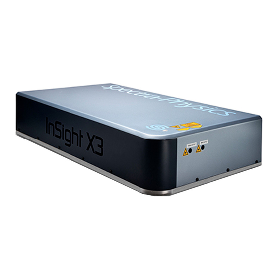
InSight X3
Spectra-Physics InSight X3 Manuals
Manuals and User Guides for Spectra-Physics InSight X3. We have
1
Spectra-Physics InSight X3 manual available for free PDF download: User Manual
Spectra-Physics InSight X3 User Manual (146 pages)
Laser System
Brand:
Spectra-Physics
| Category:
Laboratory Equipment
| Size: 3 MB
Table of Contents
Preface
3
Environmental Specifications
5
Warning Conventions
7
Standard Abbreviations
9
Table of Contents
11
List of Figures
15
List of Tables
18
Figure 1-1 Insight X3 Mode-Locked Laser System
19
Insight X3 Laser System
19
Introduction
19
Control Software
20
IPS-300 Power Supply
20
Patents
20
Specifications
20
Thermorack 401 Chiller
20
Table 1-1 Optical Specifications
21
Figure 1-2 Typical Tuning Curve
23
Typical Tuning Curve
23
Figure 1-3 Outline Drawing, Laser Head Top View
24
Figure 1-4 Outline Drawing, Laser Head, Side View
24
Laser Head
24
Outline Drawings
24
Figure 1-5 Outline Drawing, Laser Head, Front View
25
Figure 1-6 Outline Drawing, Laser Head, Rear View
25
Figure 1-7 Outline Drawing, Power Supply, Front View
25
Power Supply
25
Figure 1-8 Outline Drawing, Power Supply, Side (Left) and Rear (Right) Views
26
Figure 1-9 Outline Drawing, Power Supply and Chiller Rack
26
Important Safety Notes
27
Laser Safety and Compliance
27
Safety Precautions for Class IV High Power Lasers
27
Figure 2-1 Safety Warning Labels (en 60825-1: 2007, ANSI Z136.1 Section 4.7)
28
Figure 2-2 Beam Block
28
Emission Connector
29
Emission Indicator
29
Safety Devices
29
Cover Safety Interlocks
30
Figure 2-5 Laser Head Safety Devices
30
Interlock Keyswitch
30
Shutter
30
Figure 2-6 Power Supply Safety Devices
31
On/Off AC Power Switch
31
CDRH Requirements for Operating the Laser System
32
Interlock Connector
32
Maintenance for CDRH Compliance
32
CE/CDRH Radiation Control Drawings
33
Figure 2-9 CE/CDRH Radiation Control Drawing, Laser Head, Rear View
34
Figure 2-10 CE/CDRH Radiation Control Drawing, IPS-300 Power Supply
35
CE/CDRH Warning Labels
36
Figure 2-11 CE/CDRH Warning Labels
36
Label Translations
36
Table 2-1: Label Translations
37
WEEE Recycling Label
37
CE Declaration of Conformity
38
Laser Safety Standards
39
Sources for Additional Information
39
Equipment and Training
40
Chapter 3: Controls, Indicators, and Connections
41
Introduction
41
Laser Head
41
Controls
41
Indicators
42
Connections
42
Figure 3-2 Mating Interlock Connector
43
IPS-300 Power Supply
44
Figure 3-3 Mating Emission Connector
44
Figure 3-4 Typical Waveform
44
Front Panel
45
Rear Panel
46
Figure 3-6 Power Supply Rear Panel
46
Connector Interface Descriptions
47
RS-232 Port Connector
47
Emission Connector
47
Safety Interlock Connector
48
Figure 3-8 Laser Head Emission Connector and Circuit
48
Figure 3-9 Laser Head Interlock Connector
48
Table 3-2 Emission Connector Pin Descriptions
48
Table 3-3 Interlock Connector Pin Descriptions
48
Chiller
49
Chapter 4: Receiving and Inspecting
50
Inspecting the Shipment
50
Exterior Inspection
50
Figure 4-1 Tilt and Shock Watches
50
Packaging Description
51
Figure 4-2 Crate with Latches Unfastened
51
Figure 4-3 Open Crate Showing Laser Head (Top Layer) and Its Cover (Middle Layer)
52
Figure 4-4 Power Supply, Chiller, and Rack Crate
53
Figure 4-5 Cover Removed from the Power Supply, Chiller, and Rack Crate
53
If Damage to the Box(Es) Is Apparent
54
Figure 4-6 Power Supply Box Shown Open with Center Foam Piece Removed
54
Figure 4-7 Power Supply Box Shown with Inner Bag Opened
54
Packing the Laser System for Transportation or Return to Spectra-Physics
55
Figure 4-8 Chiller Box Opened with Foam Pieces Removed
55
Chapter 5: Installation
56
System Installation
56
Site Considerations
56
System Installation Considerations
56
Chiller Requirements
57
Installing the Control Software
58
Installing the USB Driver
59
Figure 5-2 Install Screen
59
Figure 5-3 Installation Successful Message
59
Figure 5-4 Found New Hardware Message
59
Installing the GUI Control Software
60
Chapter 6: Operation
62
Deepsee Component
62
Objective Tables
63
Using the Chiller
64
Operating the System Using the GUI Control Software
65
Figure 6-1 User Interface Overview, Showing Main Tab
65
The Left Panel
66
Figure 6-2 GUI Shutdown Choices
66
Figure 6-3 Left Panel: Standard System Showing a Fault (Left), IR Option System (Right)
67
The Right Panel
68
Turning on the System
68
Figure 6-4 Right Panel, Main Tab
68
Turning off the System
70
Figure 6-5 Main Tab Display Showing Laser on and Shutter Open
70
Main Tab
71
Figure 6-7 Main Tab Display
72
Objectives Tab
73
Figure 6-8 Objectives Tab Display
74
Figure 6-9 Upper Section of the Objectives Tab
75
Figure 6-10 Default Lower Section Display of Objectives Tab
76
Figure 6-11 New Objective Panel
76
Diagnostics Tab
78
Figure 6-12 Upper Section of Objectives Tab
78
Figure 6-13 Diagnostics Tab
79
About Tab
81
Figure 6-14 about Tab
82
Maintenance and Diagnostics
84
Maintenance
84
Chiller Maintenance Tips
85
Chiller Coolant
85
Chiller Filter
86
Figure 7-1 Hose with Filter Attached
86
Figure 7-2 Unscrew Filter Assembly Bottom
87
Figure 7-3 Replace Filter in Assembly
87
Diagnostics
88
Preliminary Verification
88
Troubleshooting Guide
88
Figure 7-4 Plug Hose Back into Chiller
88
Replacement Parts
90
Table 7-3 Field Replaceable Units
90
Customer Service
92
Warranty
92
Instrument Repair
93
Service Centers
93
Table 8-1 Service Centers
93
Appendix A: Programming Guide
98
Command/Query/Response Format
98
Typical Command Usage
99
Commands and Queries
99
Quick Reference
99
Full Description
100
Table A-1 Status Byte (*STB) Details
105
Deepsee Commands
106
Table A-2 State Definitions
106
Using the RS-232 and USB Serial Ports
108
Pinout/Wiring for
108
Communications Parameters for
108
Table A-3 RS-232 Pin Assignments
108
Using the USB Port
109
Appendix B: Status Codes
110
Status Codes
110
Table B-1: Status Codes Reported by the READ:AHIS? Command
111
Appendix C: Mode Locking and GVD Compensation
112
Mode Locking
112
Figure C-1 Amplitude and Frequency of Longitudinal Modes in Mode-Locked Laser
112
Group Velocity Dispersion (GVD
113
Figure C-4 Typical Pulse Spreading Due to GVD
114
Figure C-5 System with Precompensation Providing Shortest Pulse at Sample
114
Appendix D: Nalco MSDS
116
Log/Notes
134
Report Form for Problems and Solutions
140
Index
142
Advertisement
Advertisement
Related Products
Spectra-Physics Millennia Pro
Spectra-Physics Pulseo 355-10
Spectra-Physics Pulseo 355-20
Spectra-Physics Pulseo 355-8-300
Spectra-Physics Pulseo 532-34
Spectra-Physics Pulseo Series
Spectra-Physics Quanta-Ray GCR-12
Spectra-Physics Quanta-Ray GCR-14
Spectra-Physics Quanta-Ray GCR-16
Spectra-Physics Quanta-Ray GCR-18
Spectra-Physics Categories
Laboratory Equipment
Measuring Instruments
Industrial Equipment
More Spectra-Physics Manuals
Login
Sign In
OR
Sign in with Facebook
Sign in with Google
Upload manual
Upload from disk
Upload from URL