Sign In
Upload
Manuals
Brands
Spectra-Physics Manuals
Laboratory Equipment
Pulseo 355-10
Spectra-Physics Pulseo 355-10 Manuals
Manuals and User Guides for Spectra-Physics Pulseo 355-10. We have
1
Spectra-Physics Pulseo 355-10 manual available for free PDF download: User Manual
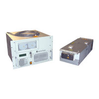
Spectra-Physics Pulseo 355-10 User Manual (179 pages)
High Peak Power, Diode Pumped, Q-Switched Laser System
Brand:
Spectra-Physics
| Category:
Laboratory Equipment
| Size: 5 MB
Table of Contents
Table of Contents
15
Preface
5
Environmental Specifications
7
Warning Conventions
9
Standard Abbreviations
11
Table of Contents
15
List of Figures
21
List of Tables
24
Chapter 1: Introduction
25
Figure 1-1 Pulseo Laser Head and Power Supply
25
Pulseo Laser System
26
D-Series Power Supply
26
System Control
27
Environmental Control
27
Patents
28
Table 1-1 Pulseo System Patents
28
Chapter 2: Laser Safety and Compliance
29
Important Safety Notes
29
Maximum Emission Levels
30
Safety Precautions for Class IV High Power Lasers
30
Table 2-1 Maximum Emission Levels
30
Safety Device Locations
31
Emission Indicators
31
Figure 2-1 Safety Warning Labels (en 60825-1: 2007, ANSI Z136.1 Section 4.7)
31
Figure 2-2 Beam Dump
31
Safety Interlocks
32
Figure 2-3 Pulseo Laser Head Indicators
32
Figure 2-4: EMISSION Connector Schematic
32
Shutter
33
Figure 2-5 D-Series Power Supply Interlock Connector and USB Port
33
On/Off Controls and Power Indicator
34
Keyswitch Interlock/Secondary on and off
34
Operating the Laser Via a User-Created GUI
34
CRDH Drawings and Labels
35
D-Series Power Supply Safety Devices
35
Figure 2-6 D-Series Power Supply Safety Devices, Front (Model D400)
35
Figure 2-7 D-Series Power Supply Safety Devices, Rear (Model D400)
36
Safety Warning Labels
37
Figure 2-8 Safety Warning Labels
37
Figure 2-9 Pulseo Laser Head Radiation Control Features, Top
38
Figure 2-10 Pulseo Laser Head Radiation Control Features, Side
38
Figure 2-11 Pulseo Laser Head Radiation Control Features, Front (Left) and Rear (Right)
38
D-Series Power Supply Radiation Control
39
Figure 2-12 D-Series Power Supply Radiation Control Features (Model D400)
39
CE Declaration of Conformity
40
WEEE Recycling Label
41
Other Hazards
41
Additional Safety Resources
41
Laser Safety Standards
41
Equipment and Training
42
Chapter 3: Pulseo Laser Description
45
Overview
45
System Components
45
Accessory Kit Parts List
45
Chiller
46
Nalco
46
Key Features
46
Pulseo Laser Design
46
Laser Cavity Design
46
Q-Switching
47
Frequency Doubling and Tripling
47
Laser Power Monitor
48
Shutter Control
48
E-Pulse™ Constant Energy Feature
49
Eternalign
49
Data Log
49
Condensation Alarm
50
System Component Descriptions
50
System Control
50
D-Series Power Supply
50
Diode Module
50
Laser Head
51
Active Laser Purification System (ALPS)
51
Non-Optical Specifications
51
Utilities (Power Requirements)
51
Fuse Requirements
52
Specifications
52
Outline Drawings
52
Laser Head
52
Figure 3-2 Pulseo Laser Head Outline, Side View
53
Figure 3-3 Pulseo Laser Head Outline, Bottom View
53
Figure 3-4 Pulseo Laser Head Outline, Front (Left) and Rear (Right) View
53
Figure 3-5 Laser Head Mounting Holes
54
Power Supply
55
Figure 3-6 D-Series Power Supply Outline, Front
55
Figure 3-7 D-Series Power Supply Outline, Side
55
Block Diagrams
56
Electrical Diagrams (Interlock)
56
Figure 3-8 Interlock Safety Block Diagram
56
Chapter 4: Controls, Indicators, and Connections
59
Pulseo Laser Head
59
Controls
59
Indicators
59
Figure 4-1 Pulseo Laser Head Indicators
59
Connectors
60
Table 4-1 Pulseo Laser Head Indicators
60
Table 4-2 Pulseo Laser Head Rear Panel Connectors
60
Table 4-3 Pulseo Laser Head Shutter Control Connector Pins
61
D-Series Power Supply
62
Front Panel Features
62
Figure 4-4 Front Panel of D-Series Power Supply
62
Table 4-4 D-Series Power Supply Front Panel Features
63
Rear Panel Features
64
Table 4-5 D-Series Power Supply Top Rear Panel Controls
64
Opto-Isolated Connections of the LASER CONTROL Interface
66
Opto-Isolator Description
67
Opto-Isolator Inputs
67
Table 4-8: LASER CONTROL 25-Pin Connector Descriptions
68
Table 4-10 D-Series Power Supply Bottom Rear Panel Connections
71
Chiller
72
Table 4-11 Chiller Output Specifications
72
Chapter 5: Preparing for Operation
73
Installing the USB Driver and User GUI Software
73
Installing the Pulseo USB Driver
73
Figure 5-1 Preinstaller Icon
74
Figure 5-2 Install Driver Screen
74
Figure 5-3 Installation Successful Screen
74
Installing the Pulseo GUI Control Software
75
Chapter 6: Operation
77
Pulseo GUI Control Panel
77
Figure 6-1 Pulseo GUI Control Panel, 532 System
78
Figure 6-2 Pulseo GUI Control Panel, 355-20 System
78
Figure 6-3 Pulseo GUI Control Panel, 355-10 System
79
Table 6-1 Controls on the Pulseo GUI Control Panel
79
First Power up and Initial Startup
82
Turn on / Turn off Sequence
86
The Shutter Control Interface
86
Table 6-2 Shutter Configurations
86
Mode 1: Using Serial Commands
87
Mode 2: Using the Laser Control Connector
87
Mode 3: Via the Shutter Control Connector on the Laser Head
88
Safety Mode and Process Mode
88
Adjusting UV Pulse Energy by Pulse Width Modulation
89
Case 1: Full-Pulse Energy
90
Figure 6-4 Full-Pulse Energy
90
Case 2: Reduced-Pulse Energy
91
Figure 6-5 Reduced-Pulse Energy
91
Case 3: Minimal Pulse Energy
92
Figure 6-6 Minimal Pulse Energy
92
Case 4: Generating Bursts
93
Figure 6-7 Generating Bursts
93
Case 5: Burst with Reduced Pulse Energy
94
Control Methods
94
Figure 6-8 Burst with Reduced Pulse Energy
94
External-Triggering Timing Nomenclature
95
Method A: Internal Trigger and Internal Gate
95
Method B: Internal Pulse Trigger: External Gating Via ENABLE BNC
96
Figure 6-10 Internal Triggering Operating Method
96
Figure 6-11 ENABLE BNC Internal Triggering Operating Method
96
Table 6-3 Internal Gating Operating Method Summary
96
Method C: Internal Pulse Trigger: External Gating Via LASER CONTROL
97
Figure 6-12 Laser Control Internal Triggering Operating Method
97
Table 6-4 External Gating Via ENABLE BNC Operating Method Summary
97
Method D: External Pulse Trigger: One-Pin Operation, Constant Frequency
98
Figure 6-13 One-Pin Operation, Constant Frequency External Pulse Trigger Method
98
Method E: External Pulse Trigger: One-Pin Operation, Variable Frequency
99
Method F: External Pulse Trigger: External Gating
99
Figure 6-14 One-Pin Operation, Variable Frequency External Pulse Trigger Method
99
Figure 6-15 External Gating Pulse Trigger Operating Method
99
Table 6-7 External Pulse, One Pin, Variable Frequency
99
Method G: External Pulse Trigger: Equalizing the First Pulse
100
Figure 6-16 Equalizing the First Pulse External Pulse Trigger Operating Method
100
Operation
101
System Shut down
101
Short Term or Overnight
101
Figure 6-17: Running below E Freq External Pulse Trigger Operating Method
101
Table 6-10 Operating Method Summary, External Triggering
101
Extended Turn off
102
Chapter 7: Maintenance
103
Filter Cleaning Recommendations
103
Cleaning the D-Series Power Supply Filters and Grills
103
Changing the ALPS Filters
104
Figure 7-1 Access Panel Screw Locations
104
Figure 7-2 Disconnecting Cover Plate
105
Figure 7-3 Removing Cover Plate
105
Figure 7-4 Disconnecting Air Lines
105
Figure 7-5 Closing Open Connections
106
Figure 7-6 Sliding out Filter Assembly
106
Figure 7-7 Disconnecting Filter Assembly from Air Lines
106
Figure 7-8 Empty Chamber
107
Figure 7-9 New Filter Assembly
107
Low Output Power Recovery and Optimization
108
Optimizing Output Power
108
Figure 7-10 Kinked Air Line
108
Tuning Harmonic Crystal Temperatures
109
Translating the THG Crystal
110
Figure 7-11 Overall Sequence of THG Crystal Movement
110
Translating the SHG Crystal
111
Figure 7-12 Available SHG Spots
112
Important Notes on Controlling Pulseo Output Power
113
Adjusting Diode Current
113
Changing Output Power
113
Cautionary Note on Changing Power
114
Diode Laser Current Limit
114
Chiller Maintenance
115
Changing the Coolant
115
Coolant Hoses
116
Chapter 8: Diagnostics and Troubleshooting
117
Fault Codes
117
System Events
117
Table 8-1 System Events
118
Chapter 9: Customer Service
121
Warranty
121
Contacting Customer Service
121
Return Policy and Instructions
122
Service Training Programs
122
Service Centers
123
Table 9-1 Service Centers
123
Chapter 10: Field Replaceable Units (Frus)
125
Appendix A: Serial Command Interface
129
Conventions
129
Basic Commands
129
Important Commands
135
Less Common Commands
140
Appendix B: Nalco MSDS
149
Form for Problems and Solutions
165
Advertisement
Advertisement
Related Products
Spectra-Physics Pulseo 355-20
Spectra-Physics Pulseo 355-8-300
Spectra-Physics Pulseo Series
Spectra-Physics Pulseo 532-34
Spectra-Physics 3980
Spectra-Physics 3980-1
Spectra-Physics 3980-2
Spectra-Physics 3980-3
Spectra-Physics 3980-4
Spectra-Physics 3980-5
Spectra-Physics Categories
Laboratory Equipment
Measuring Instruments
Industrial Equipment
More Spectra-Physics Manuals
Login
Sign In
OR
Sign in with Facebook
Sign in with Google
Upload manual
Upload from disk
Upload from URL