Sign In
Upload
Manuals
Brands
Sony Manuals
Camcorder
DVCAM DSR-PD150
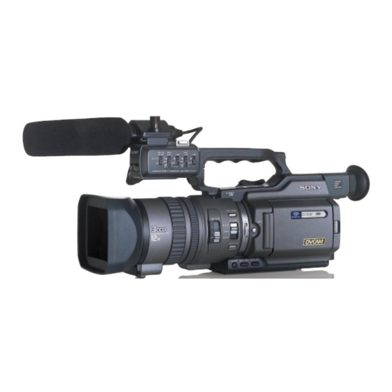
Sony DVCAM DSR-PD150 Manuals
Manuals and User Guides for Sony DVCAM DSR-PD150. We have
6
Sony DVCAM DSR-PD150 manuals available for free PDF download: Service Manual, Operating Instructions Manual, Brochure & Specs
Sony DVCAM DSR-PD150 Service Manual (279 pages)
Brand:
Sony
| Category:
Camcorder
| Size: 33.97 MB
Table of Contents
Table of Contents
3
Block Diagrams
4
Schematic Diagrams
4
Service Note
7
Power Supply During Repairs
7
To Take out a Cassette When Not Eject
7
Self-Diagnosis Function
8
Self-Diagnosis Display
8
Service Mode Display
8
Display Method
8
Switching of Backup no
8
End of Display
8
Self-Diagnosis Code Table
9
General
10
Auto Logo Insert for Copyright Protection
52
Disassembly
55
Lcd Section (Hl-011, Pd-126 Boards, Inverter Transformer Unit)
56
Evf Section (Lb-065D Board)
57
Upper Handle Block Assembly
58
Fk-076, Ma-386D Boards
58
Boards
59
Cabinet (L) Block Assembly, Mechanism Deck, VC-242D, DD-138D, Jk-190 Boards
60
Section Check)
60
Cabinet (R) Block Assembly
62
Cabinet Bottom (D) Assembly
62
Battery Panel Block Assembly (Mk-014, Kp-010, Ms-049 Boards)
63
Evf Block Assembly
63
Mechanism Deck
65
Lens Block Assembly, Center Frame
65
Assembly
66
Assembly
67
Control Switch Block (Ps-4980
70
Control Switch Block (Cf-4980)
70
Control Switch Block (Ed-4980)
70
Flexible Boards Location
70
Mounted Parts Location
139
Adjustments
145
Before Starting Adjustment
145
Adjusting Items When Replacing Main Parts and Boards
146
Camera Section Adjustment
148
List of Service Tools
148
Preparations before Adjustment
148
Preparations
150
Order of Adjustments
152
Precaution
152
Setting the Switch
152
Subjects
152
Initialization of A, B, C, D, E, F, 8 Page Data
153
Modification of C, D, 8 Page Data
153
Initializing the a Page Data
156
Page Table
156
Initialization of B Page Data
157
Modification of E Page Data
158
Modification of E, F Page Data
158
(VC-242D Board)
161
Camera System Adjustments
161
Mhz Origin Oscillation Adjustment
161
Zoom Key Center Adjustment
161
HALL Adjustment
162
Offset Adjustment
162
Flange Back Adjustment (Using Minipattern Box)
163
Flange Back Adjustment
164
Flange Back Adjustment (1)
164
Flange Back Adjustment (2)
164
More than 500M Away)
164
Flange Back Check
165
Picture Frame Setting
165
Auto White Balance Standard Data Input
166
Pre White Balance Data Input
166
LV Standard Data Input
167
MAX GAIN Adjustment
167
White Balance ND Filter 1 Compensation
168
White Balance ND Filter 2 Compensation
168
Auto White Balance Adjustment
169
Color Reproduction Adjustment (ND Filter OFF)
169
Color Reproduction Adjustment (ND Filter 1)
170
Color Reproduction Adjustment (ND Filter 2)
170
White Balance Check
171
Steady Shot Adjustment
172
Steady Shot Adjustment (1)
173
Steady Shot Adjustment (2)
174
Adjustment
175
Electronic Viewfinder System
175
VCO Adjustment (VC-242D Board)
175
Bright Adjustment (1) (VC-242D Board)
176
Bright Adjustment (2) (VC-242D Board)
176
(VC-242D Board)
177
Backlight Consumption Current Adjustment
177
Contrast Adjustment (VC-242D Board)
177
Lcd System Adjustment
178
VCO Adjustment (PD-126 Board)
178
Black Limit Adjustment (PD-126 Board)
179
Bright Adjustment (PD-126 Board)
179
Center Level Adjustment (PD-126 Board)
180
Contrast Adjustment (PD-126 Board)
180
V-COM Adjustment (PD-126 Board)
181
White Balance Adjustment (PD-126 Board)
181
Auto Test
182
For Adjustment
182
Manual Test
182
Mechanical Section Adjustment
182
Mechanism Condition (Position) Shifting Order List
182
Mode Selector II (A-6082-282-A) Connection
182
Outline
182
Parts Replacement and Preparation
182
Step Test
182
The Mechanical Adjustment Requires the Following
183
Drum Assembly and Drum Base Block Assembly
184
Parts Replacement
184
Tape Fall Stopper, HC Roller and HC Arm
184
Damper Assembly, Cassette Compartment Assembly
185
Reel Table (S) / Reel Table (T) Assembly
186
Brake Slider Assembly, Pinch Slider Assembly and Cam Gear
187
Cassette Base Block Assembly, Gooseneck Gear
187
TG1 Adjustment Plate Assembly, Tension Coil Spring (TG1), TG1 Arm Assembly, TG7 Retainer Spring and TG7 Arm Block Assembly
187
GL Block Assembly, GL Driving Gear and HC Driving
188
Pinch Arm Assembly, Torsion Spring (TG7LD), Pinch
188
Capstan Motor, Conversion Pulley, Timing Belt and Holder
189
L Motor Block Assembly and FP-594 Flexible Board
190
Extension Spring
191
Reset Arm (S), Brake (S), Brake Rack (S), Brake (T)
191
(Gls) / (Glt)
192
Coaster (S) / (T) Assembly, GL Arm (S) / (T) Assembly
192
Check and Adjustment
194
FWD Back Tension Checking and Adjustment
194
FWD Position Checking and Adjustment
194
Reel Table (S) / Reel Table (T) Torque Check
194
Preparation for Tape Path Checking and Adjustment
197
Play Mode
198
TG7 Slack Checking and Adjustment
198
Track Checking and Adjustment
198
CUE / REV Check
199
Curl Checking and Adjustment
199
Rising Check
199
Cleaning of Rotary Drum Assembly
200
Cleaning of Tape Path System
200
Periodic Check
200
Periodic Checks
200
Equipment Required
201
Preparations before Adjustments
201
Video Section Adjustments
201
Cassette
202
How to Enter Playback Mode Without
202
How to Enter Record Mode Without
202
Precautions on Adjusting
202
Adjusting Connectors
203
Connecting the Equipment
203
Alignment Tapes
204
Input/Output Level and Impedance
204
Company ID Input
205
Initialization of A, B, C, D, E, F, 8 Page Data
205
Serial No. Input
205
System Control System Adjustment
205
Battery End Adjustment
207
Cap FG Duty Adjustment (VC-242D Board)
208
PLL F & LPF F Adjustment (VC-242D Board)
208
Servo and Rf System Adjustment
208
T Reel FG Duty Adjustment (VC-242D Board)
208
AGC Center Level Adjustment (VC-242D Board)
209
AGC Center Level and APC & AEQ Adjustment
209
Preparations before Adjustments
209
Switching Position Adjustment (VC-242D Board)
209
APC & AEQ Adjustment (VC-242D Board)
210
PLL F & LPF F
210
Processing after Completing Adjustments
210
Base Band Block Adjustments
211
Chroma BPF F Adjustment (VC-242D Board)
211
S VIDEO out y Level Adjustment (VC-242D Board)
211
Video System Adjustments
211
(VC-242D Board)
212
S VIDEO out Chroma Level Adjustment
212
VIDEO out Y, Chroma Level Check (VC-242D Board)
212
BIST Check
213
IC301 AUD (ABUS) PB bist Check
213
IC301 TRX (RF) PB bist Check
213
IC301 VFD PB bist Check
213
Playback System Check
213
Preparations for Playback
213
IC301 ENCODER bist Check
214
Processing after Completing Playback System Check
214
Audio System Adjustments
215
Overall Distortion Check
216
Overall Level Characteristics Check
216
Overall Noise Level Check
216
Overall Separation Check
216
Playback Level Check
216
Adjustment Remote Commander
217
Commander
217
Precautions Upon Using the Adjustment Remote
217
Service Mode
217
Using the Adjustment Remote Commander
217
Data Process
218
Emergence Memory Address
219
EMG Code (Emergency Code)
219
Service Mode
219
Setting the Test Mode
219
MSW Code
220
Bit Value Discrimination
221
Switch Check (1)
221
Record of Use Check
222
Switch Check (2)
222
Record of Self-Diagnosis Check
223
HRS METER (Hours Meter)
224
Exploded Views
225
Overall Section-1
225
Repair Parts List
225
Overall Section-2
226
Cabinet (L) Section
227
Cabinet (R) Section-1
228
Cabinet (R) Section-2
229
Upper Handle Section
230
Battery Panel Section
231
Evf Section
232
Center Frame Section
233
Lens Block Section
234
Cassette Compartment, Drum and
235
Tape Guide, Pinch Slider Assembly and
236
Each Gears and Loading/Capstan Motor
237
Electrical Parts List
272
Revision History
279
Advertisement
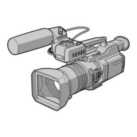
Sony DVCAM DSR-PD150 Operating Instructions Manual (172 pages)
Sony Operating Instructions Digital Camcorder DSR-PD150
Brand:
Sony
| Category:
Camcorder
| Size: 5.13 MB
Table of Contents
Operating Instructions
1
Declaration of Conformity
2
Table of Contents
3
Quick Start Guide
4
Recording a Picture
5
Getting Started
6
Using this Manual
6
Precautions on Camcorder Care
7
Checking Supplied Accessories
8
Step 1 Installing the Microphone
9
Step 2 Preparing the Power Supply
10
Charging the Battery Pack
11
Charging Time
12
Recording Time
12
Playing Time
13
Connecting to a Wall Outlet
14
Step 3 Inserting a Cassette
15
Recording - Basics
16
Recording a Picture
16
Adjusting the Lcd Screen
18
Adjusting the Brightness of the Lcd Screen
19
Adjusting the Viewfinder
20
Using the Zoom Feature
21
Indicators Displayed During Recording
22
Shooting Backlit Subjects (BACK LIGHT)
23
Spot Light
24
Checking the Recording - END SEARCH / EDITSEARCH / Rec Review
25
Playback - Basics
26
Playing Back a Tape
26
Using the Data Code Function
28
Various Playback Modes
29
Viewing the Recording on TV
31
Advanced Recording Operations
32
Recording a Still Image on a Tape - Tape Photo Recording
32
Printing the Still Image
33
Shooting with All the Pixels - PROG. SCAN
34
Using the Guide Frame
35
Using the Wide Mode
36
Using the Fader Function
37
Using Special Effects - Digital Effect
39
Shooting with Manual Adjustment
42
Adjusting the Iris
43
Adjusting the Gain
44
Adjusting the Shutter Speed
45
Using the Nd Filter
46
Shooting with the Zebra Pattern
47
Releasing the Steadyshot Function
48
Adjusting the Ae Shift
49
Adjusting the White Balance
50
Adjusting the Recording Level Manually - Sound Recording Level
52
Connecting an Optional External Microphone
54
Presetting the Adjustment for Picture Quality - Custom Preset
56
Focusing Manually
58
Interval Recording
59
Frame by Frame Recording - Cut Recording
61
Superimposing the Date and Time on a Picture
62
Marking an Index
63
Advanced Playback Operations Searching for a Recording by Index - Index Search
64
Searching the Boundaries of Recorded Tape by Title - Title Search
66
Searching a Recording by Date - Date Search
67
Searching for the Date Without Using Cassette Memory
68
Searching for a Photo - Photo Search/Photo Scan
69
Searching for a Photo Without Using Cassette Memory
70
Scanning Photo
70
Playing Back a Tape with Digital Effects
71
Editing
72
Dubbing a Tape
72
Dubbing Only Desired Scenes - Digital Program Editing
74
Erasing All Programs
79
Using with an Analog Video Unit and a PC - Signal Convert Function
80
Recording Video or TV Programs
81
Audio Dubbing
85
Adding an Audio Sound on a Recorded Tape
87
Monitoring the New Recorded Sound
87
Setting Time Values
89
Operation Mode
90
Switching the Time Value
93
Superimposing a Title
94
Erasing a Title
97
Making Your Own Titles
98
Labeling a Cassette
100
Erasing the Cassette Memory Data
102
Erasing All the Data in Cassette Memory
103
Customizing Your Camcorder
104
Changing the Menu Settings
104
Resetting the Date and Time
112
Memory Stick" Operations
113
Using a "Memory Stick" - Introduction
113
Image Quality Settings
116
Selecting the Image Quality Mode
116
Recording Still Images on a "Memory Stick" - Memory Photo Recording
118
Recording Images Continuously
119
Superimposing a Still Image in a "Memory Stick" on a Moving Picture - MEMORY MIX
121
?Memory Stick” Operations
118
Recording an Image from a Tape as a Still Image
124
Recording a Still Image from Other Equipment
125
Copying Still Images from a Tape - Photo Save
127
Viewing a Still Picture - Memory Photo Playback
129
Viewing a Still Picture – Memory Photo Playback
130
Copying an Image Recorded on a "Memory Stick" to Tapes
132
Playing Back Images Continuously - SLIDE SHOW
134
Preventing Accidental Erasure - Image Protection
135
Deleting Images
136
Writing a Print Mark - Print Mark
139
Additional Information
140
Compatibility of DVCAM and DV Formats
140
Usable Cassettes
142
Audio Mode
143
About I.link
144
Troubleshooting
145
Self-Diagnosis Display
151
Warning Indicators and Messages
152
Warning Messages
153
Using Your Camcorder Abroad
154
Maintenance Information and Precautions
155
Battery Pack
158
Specifications
160
Quick Reference
161
Identifying the Parts and Controls
161
Quick Function Guide
170
Index
171
Sony DVCAM DSR-PD150 Service Manual (141 pages)
DIGITAL CAMCORDER
Brand:
Sony
| Category:
Camcorder
| Size: 16.91 MB
Table of Contents
Dsr-Pd150/Pd150P Section 2 Disassembly
47
Repair Parts List
3
Service Note
4
Power Supply During Repairs
4
Service Mode Display
5
Table of Contents
47
Hl-011, Pd-126 Boards Service Position
48
Evf Section (Lb-065D Board)
49
Lb-065D Board Service Position
49
Upper Handle Block Assembly
50
Cabinet (L) Block Assembly, Mechanism Deck
52
For Force Eject of Cassette and Vtr Section Check
52
Mechanism Deck Service Position
53
Service Position to Check the Vtr Section
53
Cabinet (R) Block Assembly
54
Cabinet Bottom (D) Assembly
54
Ck-093 Board Service Position
54
Evf Block Assembly
55
Lens Block Assembly, Center Frame Assembly
57
CD-254, Se-108 Boards, Zoom Lens Assembly
58
Connection Diagram for Service Position (Mainly for Voltage Measurement and Check)
59
Mechanism Deck
59
Ck-093 Board
59
Dsr-Pd150/Pd150P Section 6 Repair Parts List 6-1. Exploded Views
104
Exploded Views
104
Overall Section-1
105
Cabinet (L) Section
106
Not Supplied
109
Part no
109
Ref. no
109
Bolt (M2), Spring
110
Description Remarks Ref. no
110
Flexible Board
112
Dotted Line with Mark 0 Are Critical for Safety
117
Les Composants Identifiés Par Une Marque
117
Replace Only with Part Number Specified
117
Sont Critiques Pour la Sécurité. Ne Les Remplacer que Par Une Pièce Portant
117
Electrical Parts List
117
Remote Commander (Rmt-811)
139
Advertisement
Sony DVCAM DSR-PD150 Service Manual (15 pages)
Brand:
Sony
| Category:
Camcorder
| Size: 1.23 MB
Table of Contents
Exploded Views
2
Section 6 Repair Parts List
2
Overall Section
2
Cabinet (L) Section
4
Cabinet (R) Section
5
Bolt (M2), Spring
5
Upper Handle Section
7
Battery Panel Section
8
Supplied Not
8
Evf Section
9
Center Frame Section
10
3-948-339-61 Tapping
10
Lens Block Section
11
Cassette Compartment, Drum and Reel Table Assembly
12
Tape Guide, Pinch Slider Assembly and Brake Slider Assembly
13
Each Gears and Loading/Capstan Motor Assembly
14
Sony DVCAM DSR-PD150 Brochure & Specs (6 pages)
NTSC/PAL 3CCD Digital Camcorder
Brand:
Sony
| Category:
Camcorder
| Size: 0.87 MB
Table of Contents
Camera Features
2
Recording Features
2
Operational Features
3
Optional Accessories
6
Sony DVCAM DSR-PD150 Brochure & Specs (6 pages)
NTSC/PAL 3CCD Digital Camcorder
Brand:
Sony
| Category:
Camcorder
| Size: 0.8 MB
Advertisement
Related Products
Sony DVCAM DSR-PD150P
Sony DVCAM DSR-PD100A
Sony DVCAM DSR-PD100AP
Sony DSR-PD175P/PD177P
Sony DSR PD170 - Camcorder - 380 KP
SONY DVCAM DSR-PD1
Sony DSR-PD190P
Sony DVCAM DSR-PD175P
Sony DVCAM DSR-PD177P
Sony DVCAM DSR-PD1P
Sony Categories
Laptop
TV
Camcorder
CD Player
Digital Camera
More Sony Manuals
Login
Sign In
OR
Sign in with Facebook
Sign in with Google
Upload manual
Upload from disk
Upload from URL