Sign In
Upload
Manuals
Brands
SMC Networks Manuals
Chiller
HRS018-A
SMC Networks HRS018-A Manuals
Manuals and User Guides for SMC Networks HRS018-A. We have
2
SMC Networks HRS018-A manuals available for free PDF download: Operation Manual
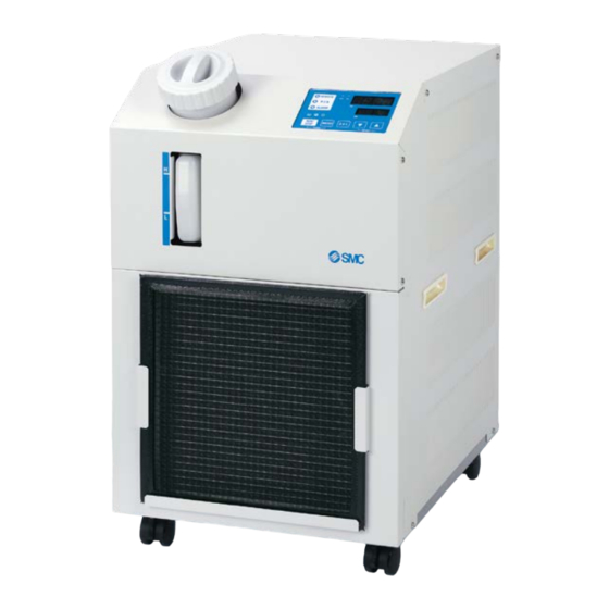
SMC Networks HRS018-A Operation Manual (162 pages)
Air-Cooled refrigerated type
Brand:
SMC Networks
| Category:
Chiller
| Size: 8 MB
Table of Contents
Table of Contents
3
Chapter 1 Safety Instructions
7
Before Using the Product
7
Reading the Manual
7
Hazards
8
Level of Hazards
8
Definition of "Serious Injury" and "Minor Injury
8
Types of Hazard Labels
9
Locations of Hazard Labels
10
Other Labels
11
Product Label
11
Safety Measures
12
Safety Instructions for Use
12
Personal Protective Equipment
13
Emergency Measures
14
Waste Disposal
15
Disposal of Refrigerant and Compressor Oil
15
Disposal of Product
15
Material Safety Data Sheet (MSDS)
15
Chapter 2 Name and Function of Parts
17
Part Number of Product
17
Name and Function of Parts
19
Function of Parts
20
Operation Display Panel
21
Chapter 3 Transport and Setting up
23
Transport
23
Transportation Using Casters
24
Installation
25
Environment
26
Location (Required Ventilation Rate)
28
Installation and Maintenance Space
29
Installation
30
Mounting
30
Electrical Wiring
31
Preparation and Wiring of Power Supply Cable
32
Wiring of Remote Operation Signal Input
36
Wiring of Operation Signal Output and Alarm Signal Output
39
Communication Wiring
40
RS-232C Communication Wiring
41
Piping
42
Fill of Circulating Fluid
44
Option J Piping Of【Automatic Fluid Filling
45
Wiring of External Switch
46
Reading of the External Switch
47
Wiring
48
Setting Items
49
Chapter 4 Starting the Product
51
Before Starting
51
Preparation for Start
52
Power Supply
52
Setting of Circulating Fluid Temperature
52
Preparation of Circulating Fluid
53
Starting and Stopping
56
Starting the Product
56
Stopping the Product
57
Check Items after Starting
58
Adjustment of Circulating Fluid
58
Chapter 5 Display and Setting of Various Functions
59
List of Function
59
Function
60
Key Operations
60
List of Parameters
62
Main Screen
65
Display on the Main Screen
65
Alarm Display Menu
66
Content of Display of Alarm Display Menu
66
Inspection Monitor Menu
67
Checking of the Inspection Monitor Menu
67
Key-Lock
71
Key-Lock
72
Key-Lock Setting / Checking
72
Run Timer, Stop Timer Function
73
Run Timer and Stop Timer Function
73
Setting and Checking of Run Timer and Stop Timer Function
75
Signal for Completion of Preparation (TEMP READY)
77
Signal for Completion of Preparation (TEMP READY)
78
Signal for Completion of Preparation (TEMP READY) Setting / Checking
78
Offset Function
80
Offset Function Setting and Checking
82
Function to Recover from Power Failure
84
Function to Recover from Power Failure
85
Function to Recover from Power Failure Setting and Checking
85
Anti-Freezing Function
86
Anti-Freezing Function
87
Anti-Freezing Function Setting and Checking
87
Key Click Sound Setting
88
Key Click Sound Setting and Checking
88
Temperature Unit Switching
89
Temperature Unit Switching Setting and Checking
89
Pressure Unit Switching
90
Pressure Unit Switching Setting and Checking
90
Alarm Buzzer Sound Setting
91
Alarm Buzzer Sound Setting and Checking
91
Alarm Customize Function
92
Alarm Customize Function
93
Alarm Customize Function Setting and Checking
94
Setting of Temperature Alarm Monitoring Method and Alarm Generation Timing
105
Data Reset Function
107
Method of Resetting Data Reset Function
107
Accumulated Time Reset Function
108
Method of Resetting Accumulated Time Reset Function
108
Communication Function
110
Communication Function Setting and Checking
110
Chapter 6 Option・Optional Accessories
127
Option B [Earth Leakage Breaker]
127
Option J [Automatic Fluid Filling]
127
Option L [Large Capacity Tank]
128
Option T [High-Pressure Pump]
129
Option V [Stainless Steel Enclosure]
129
Chapter 7 Alarm Indication and Trouble Shooting
131
Alarm Display
131
Alarm Buzzer Stop
133
Troubleshooting
134
Other Errors
136
Chapter 8 Control, Inspection and Cleaning
137
Control of Circulating Fluid Quality
137
Inspection and Cleaning
138
Daily Check
138
Monthly Check
139
Inspection Every 3 Months
140
Inspection Every 6 Months
141
Inspection for Winter Season
142
Consumables
142
Stop for a Long Time
143
Discharge of the Circulating Fluid
143
Documents
147
Specifications List
147
Product Specification
147
Refrigerant with GWP Reference
148
Communication Specifications
149
Outline Dimensions
151
Flow Chart
152
Hrs018/030-A-20-R
152
Cooling Capacity
153
Hrs018-A-20--R
153
Hrs030-A-20--R
153
Heating Capacity
154
Hrs018-A-20-R, Hrs030-A-20-R
154
Pump Capacity
155
Hrs018-A-20-R, Hrs030-A-20-R
155
Hrs018-A-20-T-R, Hrs030-A-20-T-R
155
Compliance
156
Sample Doc
157
Daily Check Sheet
158
Chapter 10 Product Warranty
159
Advertisement
SMC Networks HRS018-A Operation Manual (82 pages)
Thermo chiller
Brand:
SMC Networks
| Category:
Chiller
| Size: 1 MB
Table of Contents
Communication Function
1
Table of Contents
3
Chapter 1 Read before Using
5
Communication Mode and Operation Method
6
Communication Port
7
Key Operations
8
Parameters
10
Chapter 2 Contact Input/Output Communication
11
Precautions for Communication
11
Precautions Wiring Communication
11
Precautions after Wiring and before Communication
11
Communication Specification
12
Terminal Block Explanation
12
Setting and Checking
15
Setting and Checking
17
Hrs012-A
20
Contact Input Signal
26
Run/Stop Signal・Remote Signal
26
Signal of the External Switch
28
Contact Output Signal
29
Chapter 3 Serial Communication
31
Precautions Wiring Communication
31
Communication Specification
31
Connected Explanation
32
Chapter 4 MODBUS Communication Function
33
Precautions for Communication
33
Precautions after Wiring and before Communication
33
Precautions for Communicating
34
Communication Specification
34
Setting and Checking
35
Setting and Checking Items
35
Setting and Checking
36
Communication Sequence
39
Message Configuration
40
Message Format
40
Message Example
41
Function Codes
42
Lrc
42
Explanation of Function Codes
43
Function Code:03 Reading Multiple Registers
43
Function Code:06 Writing Registers
44
Function Code:16 Writing Multiple Registers
45
Function Code:23 Reading/Writing Multiple Registers
46
Negative Response
48
Register Map
49
Circulating Fluid Discharge Temperature
49
Circulating Fluid Discharge Pressure
49
Electric Resistivity of the Circulating Fluid
49
Status Flag
50
Alarm Flag
51
Circulating Fluid Set Temperature
53
Operation Start Command
53
Chapter 5 Simple Communication Protocol Function
55
Precautions for Communication
55
Precautions after Wiring and before Communication
55
Precautions for Communicating
56
Precautions after the Completion of the Communication
56
Communication Specification
57
Setting and Checking
58
Setting and Checking Items
58
Communication Sequence
65
Message Configuration
66
Message Format
66
Message Example
68
Bcc
69
Command
69
Command Explanation
70
Command:pv1 Circulating Fluid Discharge Temperature
70
Command:sv1 Circulating Fluid Set Temperature (R)
71
Command:sv1 Circulating Fluid Set Temperature (W)
72
Command:loc Key-Lock Setting (R)
73
Command:loc Key-Lock Setting (W)
74
Command:str Saves Data (W)
75
Negative Response
76
Chapter 6 Communication Alarm Function
77
Communication Alarm Occurs
77
Communication Alarm Reset
78
Setting and Checking
78
Setting and Checking Items
78
Advertisement
Related Products
SMC Networks HRS018-A*-10-*
SMC Networks HRS018-W*-10-*
SMC Networks HRS018-A*-20-*
SMC Networks HRS018-W*-20-*
SMC HRS018-W
SMC Networks HRS018
SMC Networks HRS012-A*-10-*
SMC Networks HRS012-W*-20-*
SMC Networks Series HRS012-A
SMC HRS012-W
SMC Networks Categories
Switch
Control Unit
Controller
Industrial Equipment
Network Router
More SMC Networks Manuals
Login
Sign In
OR
Sign in with Facebook
Sign in with Google
Upload manual
Upload from disk
Upload from URL