Sign In
Upload
Manuals
Brands
Skyjack Manuals
Lifting Systems
6832RT
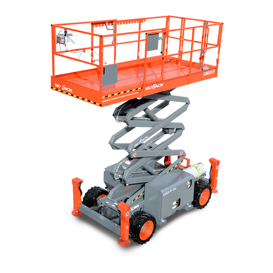
Skyjack 6832RT Scissor Lift Manuals
Manuals and User Guides for Skyjack 6832RT Scissor Lift. We have
2
Skyjack 6832RT Scissor Lift manuals available for free PDF download: Maintenance And Parts Manual
Skyjack 6832RT Maintenance And Parts Manual (251 pages)
Compact Rough Terrain Series
Brand:
Skyjack
| Category:
Lifting Systems
| Size: 17 MB
Table of Contents
Table of Contents
3
Operator Safety Reminders
7
Electrocution Hazard
7
Minimum Safe Approach Distance
7
Safety Precautions
8
Jobsite Inspection
10
List of Tables
11
Table of Contents
11
Able 2-1A Specifications and Features - ANSI/CSA
12
Able 2-1B Specifications and Features - CE
13
Able 2-1C Specifications and Features - as
14
Owner’s Annual Inspection Record
15
Able 2-2 Owner's Annual Inspection Record
15
Maximum Platform Capacities (Evenly Distributed) - ANSI/CSA
16
Maximum Platform Capacities (Evenly Distributed) - CE
16
Able 2-3B Maximum Platform Capacities (Evenly Distributed) - CE
16
Able 2-3C Maximum Platform Capacities (Evenly Distributed) - as
17
Able 2-4A Floor Loading Pressure - ANSI/CSA
18
Floor Loading Pressure
19
Locally Concentrated Pressure (LCP)
19
Overall Uniform Pressure (OUP)
19
Able 2-4B Floor Loading Pressure - CE
20
Able 2-4C Floor Loading Pressure - as
22
Able 2-5 Rough Errain Scissor Fluids
24
General Maintenance
26
Able 2-6A Maintenance and Inspection Schedule - ANSI/CSA
26
Able 2-6B Maintenance and Inspection Schedule - CE
27
Able 2-6C Maintenance and Inspection Schedule - as
28
Able 2-7A Operator's Checklist - ANSI/CSA
29
Operator’s Checklist - CE
30
Able 2-7B Operator's Checklist - CE
30
Operator’s Checklist - as
31
Able 2-7C Operator's Checklist - as
31
System Component Identification and Chematics
32
Relay Function Chart
33
Igure 3.1-1 Relay Unction Chart
33
Igure 3.1-2. Electrical Symbol Chart
34
Igure 3.1-3. Hydraulic Symbol Chart
35
Igure 3.2-1 Hydraulic Schematic Parts List
36
Hydraulic Schematic
38
Igure 3.2-3. Hydraulic Manifolds and Ports Identification
40
Igure 3.3-1. Electrical Component Parts List
42
Igure 3.3-2. Control Box Diagram - with All Options
46
Igure 3.3-3. Main Manifold Harness Wiring Diagram - ANSI/CSA
47
Igure 3.3-4. Main Manifold Harness Wiring Diagram - CE
48
Igure 3.3-5. Engine Wiring Diagram - Dual Uel System (Kubota Engine)
49
Igure 3.3-6. Engine Wiring Diagram - Diesel Uel System (Kubota Engine)
50
Igure 3.3-7. Auto-Leveling Outrigger PC Board Layout
51
Igure 3.3-8. Outrigger Optional Harness Diagram
52
Igure 3.3-9. Hydraulic Generator Electrical Panel Assembly
54
Igure 3.4-1. Electrical Panel Wiring Diagram (ANSI/CSA)
55
Igure 3.4-2. Electrical Panel Wiring Diagram (CE)
55
Electrical Schematic - Ansi/Csa
58
Igure 3.4-4. Electrical Schematic - ANSI/CSA (All Option with Kubota Dual Uel Engine)
59
Igure 3.4-6. Electrical Schematic - CE (All Option with Kubota Diesel Engine)
61
Electrical Panel Wiring Diagram - Terminal Block Details
62
Electrical Inverter Wiring Diagram
63
Igure 3.5-2. Outrigger Control Box Wiring Diagram
64
Troubleshooting
65
All Controls Inoperative
68
No Power to Platform
68
All Functions Inoperative from the Platform
68
Engine will Not Crank from Platform or Base Controls
69
Engine Cranks but will Not Tart - Kubota Diesel
70
Engine Cranks but will Not Tart - Kubota Dual Fuel
70
Glow Plugs Inoperative from Engine Controls or Platform (Diesel Models)
71
Choke Inoperative from Engine Controls or Platform (Kubota Dual Fuel)
71
High Throttle Inoperative
72
High Throttle on Demand Inoperative (Kubota Dual Fuel)
73
Drive and Teer Inoperative (Machines Without Outriggers Option)
73
Drive and Teer Inoperative (Machines with Outriggers Option)
74
Brakes will Not Release
75
Teer Right Inoperative
75
Teer Left Inoperative
75
Reverse Drive Inoperative
75
Forward Drive Inoperative
76
First Drive Speed and Steering Inoperative
77
Second Drive Speed Inoperative
77
Hird Drive Speed Inoperative
78
High Drive Speed Inoperative
79
Up Circuit Inoperative from Platform
79
Up Circuit Inoperative from Base (Base Control Box Option)
80
Up Circuit Inoperative from Platform or Base (Machines Without Outriggers)
80
Platform will Not Lift from Platform or Base Controls with Outriggers Retracted (Lift Operates Correctly with Outriggers Extended)
80
Platform will Not Lift from Platform or Base Controls with Outriggers Extended
81
Down Circuit Inoperative from Platform
82
Down Circuit Inoperative from Base
82
All Outriggers Inoperative (Auto-Level and Manual)
83
All Outriggers Inoperative (Auto-Level and Manual from Platform Controls)
83
All Outriggers Inoperative (Base Controls Only)
83
All Outriggers Inoperative (Auto Level Only)
84
Led Power Indicator Light at Outrigger Control Module (Ocm1) Flashing
85
Left Front Outrigger Inoperative Manually
86
Right Front Outrigger Inoperative Manually
86
Right Rear Outriggers Inoperative Manually
86
Left Rear Outriggers Inoperative Manually
87
Individual Outrigger Functions Inoperative (Auto-Level)
87
Auto-Level Inoperative
87
Auto All up Inoperative (Retract)
88
All Functions Inoperative
89
Steering Inoperative
89
Lift, Steer and First Drive Speed Inoperative
89
Drive Sluggish
90
Drive Inoperative When in Low Drive
90
Down Circuit Inoperative
91
All Outriggers Inoperative
91
Left Front Outriggers Inoperative
91
Right Front Outriggers Inoperative
91
Left Rear Outriggers Inoperative
92
Outriggers Drift in
92
Procedures
93
Able of Contents
93
Maintenance and Inspection
94
Maintenance and Inspection Schedule
94
Owner’s Inspections
94
Hydraulic System and Component Maintenance and Repair
95
General Pecifications
96
Torque Pecifications
97
Winching and Owing Procedures and Parking Brake System
101
To Release the Free-Wheeling Valve
101
To Release the Parking Brakes Manually
101
Disc Brakes System
101
System Lift and Pressure Adjustment
102
System Relief Pressure Adjustment
102
Lift Pressure Adjustment
102
Wheel Bolt/Nut Inspection and Torquing Procedure
103
Wheel Reinstallation and Torquing Procedure
103
Outrigger Mechanical Limit Switch Wiring
105
Auto-Leveling Outrigger Settings and Error Codes
106
Reading the Codes
106
Ed Error Codes
106
Auto-Leveling Outrigger Error Code Breakdown
107
Hand Held Calibration/Diagnostic Ool Key Functions
108
Outrigger Control Module Instructions
109
Auto-Leveling Outrigger Control Module Pin Reference Chart
112
Kubota Dual Fuel (DF972) Resistance Checks
113
Resistance of Pick-Up Sensor
113
Resistance of Ignition Coil
113
Ignitor Check Chart
113
Parts Lists
114
Parts Ordering Information
114
Method of Listing
114
How to Order Repair Parts
114
Gate Assembly
117
Platform Railings
119
Extension Platform Railings
121
Main and Extension Platform Assembly
123
Gate Latch Ssembly
125
Quick Release Pins
126
Outlet Box Assembly
128
Control Box Ssembly - Hardware
129
Drive/Steer Controller Assembly
132
Scissor Rm Control Cable Assemblies
134
Scissor Stack Assembly - Model 6826
136
Scissor Stack Ssembly - Model 6826
137
Scissor Stack Ssembly - Model 6832
139
Scissor Stack Ssembly Mounting
140
Top Lider Assembly
140
Main Platform Bracket Mounting Assembly
140
Bottom Lider Assembly
140
Scissor Stack Assembly Mounting
141
Scissor Arm Assembly Connecting Hardware
142
Limit Switch Assemblies
144
Lift Cylinder Assembly and Mounting Hardware
145
Lift Cylinder Holding Valve Assemblies Without Transducer
147
Light & Beeper Assemblies
149
Base, Axles and Wheels
151
Propane Tray Assembly
154
Steer Cylinder Assembly with Hardware
156
Tie Rod Assembly with Hardware
158
Splitter Manifold
159
Splitter Manifold Plumbing
160
Front Wheel Motor
162
Rear Wheel Motor
164
Main Manifold Plumbing
166
Hydraulic Cabinet Assembly
168
Oil Tank Assembly
170
Gas Tank Assembly
171
Main Manifold
172
Hydraulic Door Assembly
176
Engine Cabinet Assembly
177
Electrical Panel Assembly
179
Engine Installation (Kubota DF972)
181
Engine Installation (Kubota D902)
183
Tray Engine Assembly
185
Engine Door Assembly
186
Engine and Main Manifold Harness Diagrams
187
Electrical Panel Harness Diagram
189
Load Sensing Components
191
Engine Assembly (Kubota Engine DF972)
193
Air Cleaner Ssembly - Kubota Dual Fuel Engine DF972
197
Exhaust System Assembly - Kubota Engines DF972 / D902
198
Radiator Kit - Kubota DF972 / D902
199
Hydraulic Pump Ssembly (Kubota Engine DF972 / D902)
201
Propane Fuel System - Kubota Dual Fuel Engine DF972
202
Propane Fuel System - Dual Tank (Kubota Engine DF972)
204
Engine Assembly (Kubota Engine D902)
206
Air Cleaner Ssembly (Kubota Engine D902)
209
Hose Ssembly, Fuel (Kubota D902)
210
Outrigger Control Box Assembly
211
Outrigger Electrical Connections
213
Front and Rear Outrigger Assembly
216
Outrigger Assembly
218
Outrigger Cylinder Assembly
220
Outrigger Hydraulic Connections
221
Outrigger Manifold Assembly
222
800W Inverter Option
224
110/220 Clamp Assembly Option
226
Hydraulic Generator Option
228
Hydraulic Hose Connection - Hydraulic Generator Option
230
Hydraulic Generator Relay Assembly
232
Scissor Guard Option with Diesel Fuel
233
Scissor Guard with Dual Fuel
235
Work Light Option
237
Label Kit
238
Labels - Chassis (Left and Back)
239
Labels - Chassis (Top)
242
Labels - Misc
243
SJRT Scissor Fluids
247
Advertisement
Skyjack 6832RT Maintenance And Parts Manual (264 pages)
Brand:
Skyjack
| Category:
Scissor Lifts
| Size: 24 MB
Table of Contents
Table of Contents
3
Section 1 - about Your Aerial Platform
5
Aerial Platform Definition
5
Purpose of Equipment
5
Use of Equipment
5
Manuals
5
Operator
5
Service Policy and Warranty
5
Scope of this Manual
6
Operator Safety Reminders
7
Electrocution Hazard
7
Safety Precautions
8
Section 2 Maintenance Tables and Diagrams
11
Table of Contents
11
Table of Contents
66
Introduction
68
1. All Controls Inoperative
69
2. no Power to Platform
69
3. All Functions Inoperative from the Platform
69
5. Engine Cranks but will Not Start - Kubota Diesel
71
6. Engine Cranks but will Not Start - Kubota Dual Fuel
71
7. Glow Plugs Inoperative from Engine Controls or Platform (Diesel Models)
72
8. Choke Inoperative from Engine Controls or Platform (Kubota Dual Fuel)
72
9. High Throttle Inoperative
73
10. High Throttle on Demand Inoperative (Kubota Dual Fuel)
74
11. Drive and Steer Inoperative (Machines Without Outriggers Option)
74
12. Drive and Steer Inoperative (Machines with Outriggers Option)
75
13. Brakes will Not Release
76
14. Steer Right Inoperative
76
15. Steer Left Inoperative
76
16. Reverse Drive Inoperative
76
17. Forward Drive Inoperative
77
18. First Drive Speed and Steering Inoperative
78
19. Second Drive Speed Inoperative
78
20. Third Drive Speed Inoperative
79
21. High Drive Speed Inoperative
80
22. up Circuit Inoperative from Platform
80
23. up Circuit Inoperative from Base (Base Control Box Option)
81
24. up Circuit Inoperative from Platform or Base (Machines Without Outriggers)
81
25. Platform will Not Lift from Platform or Base Controls with Outriggers Retracted (Lift Operates Correctly with Outriggers Extended)
81
26. Platform will Not Lift from Platform or Base Controls with Outriggers Extended
82
27. down Circuit Inoperative from Platform
83
28. down Circuit Inoperative from Base
83
29. All Outriggers Inoperative (Auto-Level and Manual)
84
30. All Outriggers Inoperative (Auto-Level and Manual from Platform Controls)
84
31. All Outriggers Inoperative (Base Controls Only)
84
32. All Outriggers Inoperative (Auto-Level Only)
85
A: Led Power Indicator Light at Outrigger Control Module (OCM1) Not on (Constant)
85
B: Led Power Indicator Light at Outrigger Control Module (OCM1) Flashing
86
33. Left Front Outrigger Inoperative Manually
87
34. Right Front Outrigger Inoperative Manually
87
35. Right Rear Outriggers Inoperative Manually
87
36. Left Rear Outriggers Inoperative Manually
88
37. Individual Outrigger Functions Inoperative (Auto-Level)
88
38. Auto Level Inoperative
88
39. Auto All up Inoperative (Retract)
89
1. All Functions Inoperative
90
2. Steering Inoperative
90
3. Lift, Steer and First Drive Speed Inoperative
90
4. Second Drive Speed Inoperative
90
5. Drive Inoperative
90
10. Drive Inoperative When in High Drive
91
11. Brakes will Not Release
91
12. up Circuit Inoperative
91
6. Drive Sluggish
91
8. Forward Drive Inoperative
91
9. Drive Inoperative When in Low Drive
91
Reverse Drive Inoperative
91
13. down Circuit Inoperative
92
14. All Outriggers Inoperative
92
15. Left Front Outriggers Inoperative
92
16. Right Front Outriggers Inoperative
92
17. Right Rear Outriggers Inoperative
92
18. Left Rear Outriggers Inoperative
93
19. Outriggers Drift in
93
Section 5 Procedures
94
General Maintenance Hints
95
Maintenance and Inspection
95
Maintenance and Inspection Schedule
95
Owner's Inspections
95
Table 5.1 General Specifications
97
Table 5.2-1 Torque Specifications
98
Table 5.2-2 Torque Specifications
99
Table 5.3 Rough Terrain Scissor Fluids
100
System Lift and Pressure Adjustment
104
Wheel Bolt/Nut Inspection and Torquing Procedure
105
Wheel Reinstallation and Torquing Procedure
105
Auto-Leveling Outrigger PC Board Layout
106
Outrigger Mechanical Limit Switch Wiring
107
Table 5.4 Auto-Leveling Outrigger Settings and Error Codes
108
Table 5.5 Auto-Leveling Outrigger Error Code Breakdown
109
Hand Held Calibration/Diagnostic Tool Key Functions
110
Auto-Leveling Outrigger Control Module Pin Reference Chart
114
Kubota Dual Fuel (DF972) Resistance Checks
115
Electronic Tilt Switch Setup Procedure
116
Table of Contents
120
Advertisement
Related Products
Skyjack SJIII 6832E
Skyjack 6832
Skyjack 6826El
Skyjack 6826RT
Skyjack SJIII 6826E
Skyjack 6826
Skyjack 3220
Skyjack 3226
Skyjack 37 004 671
Skyjack 37 299 999
Skyjack Categories
Lifting Systems
Boom Lifts
Scissor Lifts
Forklifts
Battery Charger
More Skyjack Manuals
Login
Sign In
OR
Sign in with Facebook
Sign in with Google
Upload manual
Upload from disk
Upload from URL