Sign In
Upload
Manuals
Brands
SKF Manuals
Lubrication systems
QLS 401
SKF QLS 401 Manuals
Manuals and User Guides for SKF QLS 401. We have
2
SKF QLS 401 manuals available for free PDF download: Assembly Instructions Manual, Installation Instructions Manual
SKF QLS 401 Assembly Instructions Manual (62 pages)
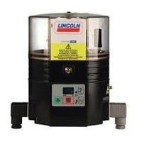
Electrically operated pump for the feeding of lubricants in interval operation inside a centralized lubrication system
Brand:
SKF
| Category:
Lubrication systems
| Size: 2 MB
Table of Contents
Masthead
4
Table of Contents
5
Safety Alerts, Visual Presentation, and Layout
7
Safety Instructions
8
General Safety Instructions
8
General Electrical Safety Instructions
8
General Behaviour When Handling the Product
8
Intended Use
8
Persons Authorized to Use the Product
8
Foreseeable Misuse
9
Referenced Documents
9
Prohibition of Certain Activities
9
Painting Plastic Components and Seals
9
Safety Markings on the Product
9
Note on the Type Plate
10
Notes on CE Marking
10
Note on Low Voltage Directive
10
Note on Pressure Equipment Directive
10
Note on UKCA Marking
10
Note on UL Mark
10
Note on ECE Mark
10
Note on EAC Marking
10
Note on China Rohs Mark
10
Emergency Shutdown
10
Assembly, Maintenance, Fault, Repair
11
First Start-Up, Daily Start-Up
11
Residual Risks
12
Lubricants
13
General Information
13
Material Compatibility
13
Temperature Properties
13
Aging of Lubricants
13
Avoidance of Faults and Hazards
13
Solid Lubricants
13
Chisel Pastes
13
Overview, Functional Description
14
Versions of the QLS System
14
Qls 301
14
Qls 401
14
Mounting Positions of the Metering Devices
15
Rear-Mounted Metering Devices
15
Bottom-Mounted Metering Devices
15
Pump for External Metering Device
15
Changing the Delivery Rate with SSV Metering Devices
16
Changing the Delivery Rate with SSVDV Metering Devices (Rear-Mounted)
16
Return of Unneeded Lubricant
17
Rear-Mounted Metering Devices
17
Bottom-Mounted Metering Device or an External Metering Device
17
Membrane Keypad
17
Shown on the Display in Display Mode of Control Circuit Board S4
18
Shown on the Display in Programming Mode of Control Circuit Board S4
19
Principle of Operation of the Intermittent Low-Level Signal
20
Operational Limits of the Intermittent Empty Signal
21
Processing of the Low-Level Signals with External Control and Monitoring of the Pump
21
Display of the Low-Level Signal
21
Remaining Running Time of the Pump with a Low-Level Signal
21
Technical Data
22
General Technical Data
22
Electrical System
23
Tightening Torques
23
Factory Settings for Pumps with Control Circuit Board S4
24
Usable Reservoir Volume
24
Lubricant Requirement When an Empty Pump Is Filled for the First Time
25
Delivery, Returns, Storage
29
Delivery
29
Return Shipment
29
Storage
29
Storage Temperature Range
29
Storage Conditions for Products Filled with Lubricant
29
Storage Period up to 6 Months
29
Storage Period between 6 and 18 Months
29
Storage Period more than 18 Months
29
Declaration of Decontamination
29
Assembly
30
General
30
Installation Location
30
Mounting Dimensions
30
Assembly Holes
31
Electrical Connection
31
Lubrication Lines
32
Connection of the Lubrication Lines
32
Maximum Length of the Lubrication Lines
32
Assembling Screw Sleeves and Hose Connectors
32
Initial Filling of a QLS 301 Pump Delivered Without Lubricant
33
Initial Filling of a QLS 401 Pump Delivered Without Lubricant
34
First Start-Up
35
General
35
Inspections before and During First Start-Up
35
Inspections before First Start-Up
35
Inspections During First Start-Up
35
Programming the Control Circuit Board S4
36
Triggering Additional Lubrication
37
Operation
37
General
37
Regular Filling Via the Filler Nipple
37
Maintenance
38
Cleaning
39
Basics
39
Interior Cleaning
39
Exterior Cleaning
39
Faults, Causes, and Remedies
40
Mechanical Faults
40
Error Messages on Pumps with Control
41
Electrical Faults on Pumps with Control
42
Electrical Faults on Pumps Without Control
42
Repairs
44
Replacing the Membrane Keypad
44
Replacing the Control Circuit Board
44
Checks after Replacing the Control Circuit Board
44
Shutdown, Disposal
45
Temporary Shutdown
45
Permanent Shutdown, Disassembly
45
Disposal
45
Spare Parts
46
SSV Metering Device for QLS 301 / 401
46
SSVDV Metering Device for QLS 401
46
Metering Screws for SSVDV Metering Devices
47
Seal Set
47
Membrane Keypad (QLS 301 / QLS 401 with Control)
47
Pump Element K6
48
Adapter M22 X 1.5
48
Quick Disconnect Couplings with Check Valve
48
Reservoir
49
Housing Cover Replacement Kit
49
VDC Motors
49
Electrical Connections
50
Control Circuit Board Replacement Kit
50
Appendix
51
Cable Colors in Accordance with IEC 60757
51
Component Abbreviations
51
Wire Assignment of the Connector Plugs
52
Circuit Diagrams
53
Circuit Diagram 12/24 V DC, with Rectangular Connector and Control Circuit Board S4
53
Circuit Diagram 120 V AC, with Rectangular Connector and Control Circuit Board S4
54
Circuit Diagram 230 V AC, with Rectangular Connector and Control Circuit Board S4
55
Circuit Diagram 12/24 V DC, with Rectangular Connector with Terminal Board
56
Circuit Diagram 12/24 V DC, with Bayonet Connector and Control Circuit Board S4
57
Circuit Diagram 230 V AC, with Rectangular Connector and Cycle Switch, Without Control Circuit Board
58
Circuit Diagram 120 V AC, with Rectangular Connector Without Control Circuit Board
59
China Rohs Table
60
Advertisement
SKF QLS 401 Installation Instructions Manual (58 pages)
Brand:
SKF
| Category:
Lubrication systems
| Size: 2 MB
Table of Contents
EC Declaration of Incorporation
2
Legal Disclosure
3
Table of Contents
4
2.2 Selection of Lubricants
4
Explanation of Symbols and Signs
6
Safety Instructions
8
General Safety Instructions
8
General Behaviour When Handling the Product
8
Qualified Technical Personnel
9
Electric Current Hazard
10
System Pressure Hazard
10
Operation
10
Assembly, Maintenance, Malfunctions Shutdown, Disposal
11
Intended Use
12
Foreseeable Misuse
12
Disclaimer of Liability
12
Referenced Documents
12
Residual Risks
13
Lubricants
14
2.1 General Information
14
2.3 Approved Lubricants
15
Lubricants and the Environment
16
Lubricant Hazards
16
Overview/ Functional Description
17
Of the SSV Metering Devices
21
Changing the Output Volume
21
Return of Unneeded Lubricant
22
Displays in the Display Mode
24
Displays in the Programming Mode
24
Technical Data
27
Factory Settings
29
Tightening Torques
30
Delivery, Returns and Storage 31
31
Electrical Devices
31
General Notes Related to the Storage
31
General Information 32
32
Minimum Installation Dimensions
33
Connecting Dimensions
34
Electrical Connection 35 36
35
Trigger Additional Lubrication
38
Operation/ Shutdown and Disposal
39
General Information
39
Temporary Shutdown
39
Shutdown and Disposal
39
Maintenance, Cleaning and Repair
40
General Information
40
Cleaning
40
Maintenance
40
Troubleshooting
41
Spare Parts
43
SSVDV Metering Device
43
Membrane Keypad
45
Motor Connections
47
Electrical Connections
47
Control Printed Circuit Boards (Pcb)
47
Circuit Diagrams
48
12/24 VDC with Control Pcb, Square
50
Attached Metering Device
51
Plug, External Metering Device
52
Plug, Attached Metering Device
53
Plug, External Metering Device
54
12/24 VDC with Control Pcb, Square
55
Plug, Attached Metering Device
55
230 VAC Without Control Pcb, with
56
Advertisement
Related Products
SKF QLS 301
SKF 24-2151-4230
SKF 24-2151-4231
SKF 24-2151-4232
SKF 24-2151-4233
SKF 24-2151-4234
SKF 24-2151-4250
SKF 24-2151-4251
SKF 24-2151-4252
SKF 24-2151-4253
SKF Categories
Water Pump
Lubrication systems
Measuring Instruments
Tools
Industrial Equipment
More SKF Manuals
Login
Sign In
OR
Sign in with Facebook
Sign in with Google
Upload manual
Upload from disk
Upload from URL