Sign In
Upload
Manuals
Brands
SKF Manuals
Lubrication systems
24-2151-4252
SKF 24-2151-4252 Manuals
Manuals and User Guides for SKF 24-2151-4252. We have
1
SKF 24-2151-4252 manual available for free PDF download: Operating Instructions Manual
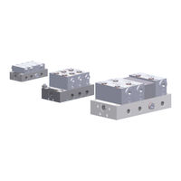
SKF 24-2151-4252 Operating Instructions Manual (106 pages)
Brand:
SKF
| Category:
Lubrication systems
| Size: 2 MB
Table of Contents
Masthead
3
Table of Contents
4
Exflanation of Symbols and Signs
7
Safety Instructions
9
General Safety Instructions
9
General Behavior When Handling the Product
9
Intended Use
10
Modifications to the Product
10
Foreseeable Misuse
11
Prohibition of Certain Activities
12
Painting Plastic Components
12
Inspections Prior to Delivery
12
Referenced Documents
12
Markings on the Product
13
Notes on the Type Plate
13
Note on CE Marking
13
Directive 2014/34/EU
14
Persons Authorized to Use the Product
14
Operator
14
Qualified Mechanic
14
Qualified Electrician
15
Potentially Explosive Atmospheres
15
Instruction of Outside Fitters
15
Provision of Personal Protective Gear
15
Operation
15
Emergency Shutdown
15
Transport, Assembly, Maintenance, Malfunction, Repair, Shutdown, Disposal
16
First Start-Up, Daily Start-Up
17
Cleaning
18
Special Safety Instructions Regarding Explosion Protection
18
Nullification of ATEX Approval
20
Operation in Potentially Explosive Atmospheres
20
Explosion Protection Marking
21
Obligations of the Operator
21
Identification of Hazards
21
Explosion Protection Measures
21
Duty to Provide Instruction and Training
22
Provision of Necessary Information
22
Residual Risks
23
Residual ATEX Risks
24
Lubricants
26
General Information
26
Selection of Lubricants
26
Material Compatibility
26
Temperature Properties
26
Aging of Lubricants
27
Solid Lubricants
28
Overview, Functional Descriftion
29
Overview of Progressive Metering Devices
29
ATEX Marking According to Directive 2014/34/EU (ATEX)
29
Information on Volume Data
30
Functioning of a PSG Progressive Metering Device
31
Information on the Design of a PSG Progressive Metering Device
32
Dummy Module
33
Consolidation of Outlets
33
Overview of a General Progressive System
34
Functional Description of a General Progressive System
35
Overview of PSG1 Progressive Metering Device Series
36
Overview of PSG2 Progressive Metering Device Series
37
Overview of PSG3 Progressive Metering Device Series
38
Technical Data
39
PSG1-ATEX General Technical Data
39
PSG1 - Basic Metering Device
39
PSG1 Pressure-Loss Diagram
41
PSG1 with Inductive Proximity Switch
42
PSG2-ATEX General Technical Data
43
PSG2 - Basic Metering Device
43
PSG2 with 2/2 Directional Solenoid Valve
45
PSG2 with Inductive Proximity Switch 24-1884-2292
46
PSG2 with Inductive Proximity Switch 24-1884-2613
47
PSG3-ATEX General Technical Data
48
PSG3 - Basic Metering Device
48
PSG3 with Inductive Proximity Switch 24-1884-2292
50
Delivery, Returns, Storage
51
Delivery
51
Return Shipment
51
Storage
51
Storage Temperature Range
52
Storage Conditions for Parts Filled with Lubricant
52
Storage Period up to 6 Months
52
Storage Period between 6 and 18 Months
53
Storage Period more than 18 Months
53
Assembly
54
General Information
54
Assembly Location
54
Mechanical Connection
55
Minimum Mounting Dimensions
55
Installing the PSG1
56
Basic Design PSG1-ATEX
56
PSG1 Tightening Torques
57
PSG1-ATEX with Visual Cycle Indicator (ZY)
58
PSG1-ATEX with Visual Cycle Indicator, Housing, and Inductive Proximity Switch (ZS)
59
Assembly PSG2-ATEX
60
Basic Design PSG2-ATEX
60
PSG2 Tightening Torques
61
PSG2-ATEX with Visual Cycle Indicator (ZY)
62
PSG2-ATEX with Pressure-Resistant Inductive Proximity Switch 24-1884-2292
63
PSG2-ATEX with Pressure-Resistant Inductive Proximity Switch 24-1884-2613
64
PSG2-ATEX with 2/2 Directional Solenoid Valve 24-1884-2292
65
Assembly PSG3-ATEX
66
Basic Design PSG3
66
PSG3 Tightening Torques
67
PSG3-ATEX with Visual Cycle Indicator (ZY)
68
PSG3 with Cycle Indicator, Housing, and Inductive Proximity Switch 24-1884-2292
69
Installing a PSG Modular Metering Device
70
Consolidation of Outlets
71
Changing a PSG Module
72
Connecting the Lubricant Lines
73
Installing the Lubrication Piping
74
Attachment of Bridges (Crossporting)
75
Establishing Equipotential Bonding
78
Electrical Connection
79
Inductive Proximity Switch 24-1884-2288
79
Inductive Proximity Switch 24-1884-2292
79
Inductive Proximity Switch 24-1884-2613
80
Connecting Directional Solenoid Valve 24-1254-2212
80
First Start-Uf
81
Venting a Grease Progressive System
81
Venting an Oil Progressive System
82
Checklist for First Start-Up
82
Inspections before First Start-Up
83
Inspections During First Start-Up
83
Oferation
84
Cleaning
85
Cleaning Agents
85
Exterior Cleaning
85
Interior Cleaning
85
Maintenance
86
Malfunctions, Causes, and Remedies
87
Prior to Beginning Troubleshooting
87
Metering Device and System Malfunctions
88
Refairs
91
General Notes
91
Replace Inductive Proximity Switch
92
Shutdown, Disfosal
93
Temporary Shutdown
93
Permanent Shutdown, Disassembly
93
Disposal
93
Sfare Farts
94
Accessories
100
Declarations of Conformity
102
Inductive Proximity Switch 24-1884-2288
102
Inductive Proximity Switch 24-1884-2292
103
Inductive Proximity Switch 24-1884-2613
104
Directional Solenoid Valve 24-1254-2212
105
Advertisement
Advertisement
Related Products
SKF 24-2151-4230
SKF 24-2151-4250
SKF 24-2151-4231
SKF 24-2151-4258
SKF 24-2151-4232
SKF 24-2151-4251
SKF 24-2151-4233
SKF 24-2151-4234
SKF 24-2151-4253
SKF 24-2151-4665
SKF Categories
Water Pump
Lubrication systems
Measuring Instruments
Tools
Industrial Equipment
More SKF Manuals
Login
Sign In
OR
Sign in with Facebook
Sign in with Google
Upload manual
Upload from disk
Upload from URL