Sime ALU HE 200 Manuals
Manuals and User Guides for Sime ALU HE 200. We have 4 Sime ALU HE 200 manuals available for free PDF download: Design, Installation And Servicing Instructions, User, Installation And Servicing Instructions

Sime ALU HE 200 Design, Installation And Servicing Instructions (132 pages)
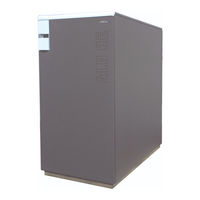
Aluminium condensation boilers
Table of Contents
Advertisement
Sime ALU HE 200 User, Installation And Servicing Instructions (124 pages)
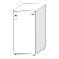
Aluminium condensation boilers
Table of Contents

Advertisement
Sime ALU HE 200 User, Installation And Servicing Instructions (92 pages)
Aluminium condensation boiler
Table of Contents
Advertisement