Sign In
Upload
Manuals
Brands
Silvus Manuals
Radio
StreamCaster SC3822
Silvus StreamCaster SC3822 Manuals
Manuals and User Guides for Silvus StreamCaster SC3822. We have
3
Silvus StreamCaster SC3822 manuals available for free PDF download: User Manual
Silvus StreamCaster SC3822 User Manual (158 pages)
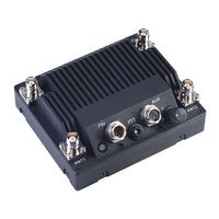
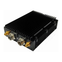
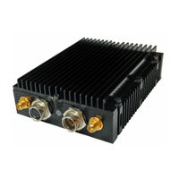
MIMO Radio
Brand:
Silvus
| Category:
Radio
| Size: 5 MB
Table of Contents
Table of Contents
4
General Safety Information
12
Health & Safety
12
Table 1 Safe Working Distances
13
Figure 1 Product Symbols with Definition
14
Maximum RF Power Density Limits
15
Introduction
16
Streamcaster Network
16
Streamcaster Hardware Overview
17
Hardware Interfaces
17
Sc4400E
17
Figure 2 Streamcaster 4400E Ruggedized Enclosure
17
Sc4200E
19
Figure 3 Streamcaster 4200E Ruggedized Enclosure
19
Sc4400
21
Sc4200
23
Sc3822
25
Sc3500/Sc3800
26
Figure 4 Streamcaster 3500/3800 Ruggedized Enclosure
26
SC3500/SC3800 with EXT Connector (PA Faceplate Option)
27
Figure 5 Streamcaster 3500/3800 Ruggedized Enclosure
27
Connector Pinouts
28
SC4400E Pinouts
28
Figure 6 SC4400E Power (Optional)/Serial/Ethernet Pinout Diagram (Cable Side)
28
Table 2 SC4400E Power/Ethernet/Serial Connector Pinout
28
Table 3 SC4400E Serial and GPS Pinout
29
Table 4 SC4400E USB/GPIO Connector Pinout (USB1 Is USB 2.0 OTG, USB2 Is USB 2.0 Host Mode Only)
30
Figure 7 SC4400E PTT Pinout Diagram (Cable Side)
31
Table 5 SC4400E PTT Connector Pinout
31
SC4200E Pinouts
32
Figure 8 SC4200E Power (Optional)/Serial/Ethernet Pinout Diagram (Cable Side)
32
Table 6 SC4200E Power/Ethernet/Serial Connector Pinout
32
Table 7 SC4200E Serial and GPS Pinout
33
Table 8 SC4200E USB/GPIO Connector Pinout (USB1 Is USB 2.0 OTG, USB2 Is USB 2.0 Host Mode Only)
34
Figure 9 SC4200E PTT Pinout Diagram (Cable Side)
35
Table 9 SC4200E PTT Connector Pinout
35
SC4400 Pinouts
36
Table 10 SC4400 Power/Ethernet/Serial Connector Pinout
36
Table 11 SC4400 Serial and GPS Pinout
36
Figure 10 SC4400 Power (Optional)/Serial/Ethernet Pinout Diagram (Cable Side)
37
Figure 11 SC4400 aux Pinout Diagram (Cable Side)
38
Table 12 SC4400 USB/GPIO Connector Pinout (USB1 Is USB 2.0 OTG, USB2 Is USB 2.0 Host Mode Only)
38
Figure 12 SC4400 PTT Pinout Diagram (Cable Side)
39
Table 13 SC4400 PTT Connector Pinout
39
SC4200 Pinouts
40
Table 14 SC4200 Power/Ethernet/Serial Connector Pinout
40
Table 15 SC4200 Serial and GPS Pinout
40
Figure 13 SC4200 Power (Optional)/Serial/Ethernet Pinout Diagram (Cable Side)
41
Figure 14 SC4200 aux Pinout Diagram (Cable Side)
42
Table 16 SC4200 USB/GPIO Connector Pinout (USB1 Is USB 2.0 OTG, USB2 Is USB 2.0 Host Mode Only)
42
Figure 15 SC4200 PTT Pinout Diagram (Cable Side)
43
Table 17 SC4200 PTT Connector Pinout
43
SC3822 Pinouts
44
Table 18 SC3822 Power/Ethernet/Serial Connector Pinout
44
Table 19 SC3822 Serial and GPS Pinout
44
Figure 16 SC3822 Power/Serial/Ethernet Pinout Diagram (Cable Side)
45
Figure 17 SC3822 USB/GPIO Pinout Diagram (Cable Side)
46
Table 20 SC3822 USB/GPIO Connector Pinout
46
Table 21 SC3822 Extension Port Pinout
47
SC3500/SC3800 Pinouts
48
Table 22 SC3500/SC3800 Power Connector Pinout
48
Table 23 SC3500/SC3800 Serial and GPS Pinout
48
Figure 18 SC3500/SC3800 Power/Serial Pinout Diagram (Cable Side) for GPS (Top) and
49
Figure 19 SC3500/SC3800 Ethernet Pinout Diagram (Cable Side)
50
Table 24 SC3500/SC3800 Ethernet Connector Pinout
50
Figure 20 SC3500/SC3800 EXT Pinout Diagram (Cable Side)
51
Table 25 SC3500/SC3800 EXT Connector Pinout
51
Mechanical and Operating Specifications
52
SC4400E Enclosure Mechanical Drawing
59
Figure 21 SC4400E Mechanical Drawing (Top) and Mounting Pattern (Bottom)
59
SC4200E Enclosure Mechanical Drawing
60
Figure 22 SC4200E Mechanical Drawing (Top) and Mounting Pattern (Bottom)
60
SC4400 Enclosure Mechanical Drawing
61
Figure 23 SC4400 Mechanical Drawing (Top) and Mounting Pattern (Bottom)
61
SC4200 Enclosure Mechanical Drawing
62
Figure 24 SC4200 Mechanical Drawing (Top) and Mounting Pattern (Bottom)
62
SC3822 Enclosure Mechanical Drawing
63
Figure 25 SC3822 Mechanical Drawing (Top) and Mounting Pattern (Bottom)
63
SC3500/SC3800 Phase II Enclosure Mounting Pattern
64
Figure 26 SC3500/SC3800 Phase II Enclosure Mounting Pattern for Back of Enclosure (Top) and Bottom
64
SC3500/ SC3800 Phase III Enclosure Mounting Pattern
65
Figure 27 SC3500/SC3800 Phase III Enclosure Mounting Pattern for Back of Enclosure (Top) and Bottom
65
SC4400E Specifications
66
SC4200E Specifications
67
SC4400 Specifications
69
SC4200 Specifications
70
SC3822 Specifications
72
SC3500 Specifications
73
SC3800 Specifications
74
Web Interface
75
Getting Started
75
Basic Configuration
75
Figure 28 Basic Configuration Page
75
Advanced Configuration
77
Figure 29 Advanced Configuration Page
77
Table 26 MCS Vs. Sensitivity Chart (5Mhz Bandwidth)
79
Table 27 MCS Vs. Sensitivity Chart (10Mhz Bandwidth)
80
Table 28 MCS Vs. Sensitivity Chart (20Mhz Bandwidth)
80
LAN/WIFI Configuration
81
Figure 30 LAN/WIFI Configuration Page
81
Multicast
85
Figure 31 Multicast Configuration Page
85
Quality of Service (Qos) #Qos
87
Figure 32 Quality of Service (Qos) Configuration Page
87
Serial/Usb Setup
91
Figure 33 Serial/Usb Setup Configuration Page
91
Node Diagnostics
93
Figure 34 Node Diagnostics Configuration Page
93
BDA Support
95
Figure 35 BDA (Bi-Directional Amplifier) Support Configuration Page
95
Build Information
96
Figure 36 Build Information
96
Security
97
Figure 37 Security (Encryption)
97
Figure 38 Security (Upgrade)
98
Figure 39 Security (Upgrade Network)
99
Figure 40 Security (License)
99
Figure 41 Security (Factory Reset)
100
Figure 42 Security (Setting Profile)
101
Figure 43 (Key Management)
102
Figure 44 (Chrome Browser Warning)
103
PTT (SC4400/SC4200 Only)
104
Figure 45 PTT (Push-To-Talk)
104
Spectrum Scan
106
Figure 46 Spectrum Scan Results
106
Figure 47 Spectrum Scan Settings
107
Figure 48 Zero Span Settings
108
Figure 49 Zero Span Results
109
MPS (Multi-Position Switch)
110
Figure 50 Multi-Position Switch
110
Admin Settings
111
Figure 51 Admin Settings
111
Figure 52 Login
111
Figure 53 Reset Password
112
Streamscape Network Manager
113
Network Topology
113
Figure 54 Silvus Streamscapenetwork Manager
113
Figure 55 Example Network Topology
114
Table 29 Color Coding for Links and Nodes
114
Figure 56 Routing Path
115
Figure 57 Custom Node Naming
116
Figure 58 Traffic Information
116
Figure 59 Individual Node Characteristics
119
Figure 60 Link Characteristics
120
Figure 61 Iperf Function Within GUI
121
Figure 62 Table View
122
Figure 63 Table View (Settings)
123
Network-Wide Setup
124
Figure 64 Network-Wide Setup
124
Per-Node Setup
125
Figure 65 Per-Node Setup
125
Map Overlay
126
Figure 66 Map Overlay
126
Figure 67 Google Maps
127
Figure 68 Offline Map Image
128
Figure 69 Placing Nodes on the Map
130
Figure 70 Cursor on Target Settings
131
FIPS Mode
132
Enable FIPS Mode
132
Potential User Errors
132
List of Security Parameters
133
Wired Backbone
134
LAN Backbone
134
Implementation
134
Use Case
134
WAN Backbone with Roaming
135
Figure 71 LAN Backbone Example
135
Implementation
136
Use Case
136
Figure 72 WAN Backbone Example
137
Custom Frequency Plan
138
Accessing and Installing CFP
138
Figure 73 Custom Frequency Page
138
Streaming Response
141
RSSI and Noise Floor Reporting
142
Table 30 RSSI Reporting Format
142
Table 31 Sample RSSI Report
143
Temperature Reporting
145
Table 32 Temperature Reporting Format
145
Voltage Reporting
146
Table 33 Voltage Reporting Format
146
Setting up an Iperf Test
147
Required Equipment
147
Running Iperf Test
147
Precautions and Recommendations
148
Saving the Radio Configuration
148
Troubleshooting
149
LED Issues
149
Intermittent Link
149
FCC Notice
150
FCC Identifier: N2S-SC3500
150
FCC Identifier: N2S-SC3822
150
FCC Identifier: N2S-SC42-245
150
FCC Identifier: N2S-SC44-245
151
FCC Identifier: N2S-SC42-520
151
FCC Identifier: N2S-SC44-520
152
FCC Identifier: N2S-SC42E-245
152
Notes
152
Notes Regarding CE Mark (SC4200-206-EB and SC4400-206-SBST Models Only)
153
Table 34 Additional Restrictions on Band C2
155
ISED Canada Notice
157
IC: 24980-Sc42E245
157
IC Statement: English
157
IC Statement: French
158
Advertisement
Silvus StreamCaster SC3822 User Manual (146 pages)
MIMO Radio
Brand:
Silvus
| Category:
Radio
| Size: 5 MB
Table of Contents
Table of Contents
4
1 General Safety Information
11
Health & Safety
13
Table 1 Safe Working Distances
13
Figure 1 Product Symbols with Definition
14
Maximum RF Power Density Limits
16
2 Introduction
17
3 Streamcaster Network
17
4 Streamcaster Hardware Overview
18
Hardware Interfaces
18
Sc4400
18
Figure 2 Streamcaster 4400 Ruggedized Enclosure
18
Sc4200
20
Figure 3 Streamcaster 4200 Ruggedized Enclosure
20
Sc3822
21
Figure 4 Streamcaster 3822 Ruggedized Enclosure
21
Sc3500/Sc3800
22
Figure 5 Streamcaster 3500/3800 Ruggedized Enclosure
22
SC3500/SC3800 with EXT Connector (PA Faceplate Option)
23
Figure 6 Streamcaster 3500/3800 Ruggedized Enclosure
23
Connector Pinouts
24
SC4400 Pinouts
24
Table 2 SC4400 Power/Ethernet/Serial Connector Pinout
24
Table 3 SC4400 Serial and GPS Pinout
25
Table 5 SC4400 PTT Connector Pinout
26
Figure 7 SC4400 Power (Optional)/Serial/Ethernet Pinout Diagram (Cable Side)
27
Figure 8 SC4400 AUX Pinout Diagram (Cable Side)
27
Figure 9 SC4400 PTT Pinout Diagram (Cable Side)
28
SC4200 Pinouts
29
Table 6 SC4200 Power/Ethernet/Serial Connector Pinout
29
Table 7 SC4200 Serial and GPS Pinout
30
Table 9 SC4200 PTT Connector Pinout
31
Figure 10 SC4200 Power (Optional)/Serial/Ethernet Pinout Diagram (Cable Side)
32
Figure 11 SC4200 AUX Pinout Diagram (Cable Side)
32
Figure 12 SC4200 PTT Pinout Diagram (Cable Side)
33
SC3822 Pinouts
34
Table 10 SC3822 Power/Ethernet/Serial Connector Pinout
34
Table 11 SC3822 Serial and GPS Pinout
35
Table 12 SC3822 USB/GPIO Connector Pinout
35
Table 13 SC3822 Extension Port Pinout
36
Figure 13 SC3822 Power/Serial/Ethernet Pinout Diagram (Cable Side)
37
Figure 14 SC3822 USB/GPIO Pinout Diagram (Cable Side)
37
SC3500/SC3800 Pinouts
38
Table 14 SC3500/SC3800 Power Connector Pinout
38
Table 15 SC3500/SC3800 Ethernet Connector Pinout
39
Table 16 SC3500/SC3800 EXT Connector Pinout
39
Table 17 SC3500/SC3800 Serial and GPS Pinout
40
Figure 15 SC3500/SC3800 Power/Serial Pinout Diagram (Cable Side) for GPS (Top) and
41
Figure 16 SC3500/SC3800 Ethernet Pinout Diagram (Cable Side)
42
Figure 17 SC3500/SC3800 EXT Pinout Diagram (Cable Side)
42
Mechanical and Operating Specifications
43
SC4400 Enclosure Mechanical Drawing
47
Figure 18 SC4400 Mechanical Drawing (Top) and Mounting Pattern (Bottom)
47
SC4200 Enclosure Mechanical Drawing
48
Figure 19 SC4200 Mechanical Drawing (Top) and Mounting Pattern (Bottom)
48
SC3822 Enclosure Mechanical Drawing
49
Figure 20 SC3822 Mechanical Drawing (Top) and Mounting Pattern (Bottom)
49
SC3500/SC3800 Phase II Enclosure Mounting Pattern
50
Figure 21 SC3500/SC3800 Phase II Enclosure Mounting Pattern for Back of Enclosure (Top) and Bottom
50
SC3500/ SC3800 Phase III Enclosure Mounting Pattern
51
Figure 22 SC3500/SC3800 Phase III Enclosure Mounting Pattern for Back of Enclosure (Top) and Bottom
51
SC4400 Specifications
52
SC4200 Specifications
53
SC3822 Specifications
55
SC3500 Specifications
56
SC3800 Specifications
57
5 Web Interface
58
Getting Started
58
Basic Configuration
59
Figure 23 Basic Configuration Page
59
Advanced Configuration
61
Figure 24 Advanced Configuration Page
61
Table 18 MCS Vs. Sensitivity Chart (5Mhz Bandwidth)
65
Table 19 MCS Vs. Sensitivity Chart (10Mhz Bandwidth)
66
LAN/WIFI Configuration
67
Table 20 MCS Vs. Sensitivity Chart (20Mhz Bandwidth)
67
Figure 25 LAN/WIFI Configuration Page
68
Multicast
72
Figure 26 Multicast Configuration Page
72
Quality of Service (Qos) #Qos
73
Figure 27 Quality of Service (Qos) Configuration Page
74
Serial/Usb Setup
78
Figure 28 Serial/Usb Setup Configuration Page
78
Node Diagnostics
80
Figure 29 Node Diagnostics Configuration Page
80
BDA Support
82
Figure 30 BDA (Bi-Directional Amplifier) Support Configuration Page
82
Build Information
83
Figure 31 Build Information
83
Security
84
Figure 32 Security (Encryption)
84
Figure 33 Security (Upgrade)
85
Figure 34 Security (Upgrade Network)
86
Figure 35 Security (License)
87
Figure 36 Security (Factory Reset)
87
Figure 37 Security (Setting Profile)
88
Figure 38 (Key Management)
90
Figure 39 (Chrome Browser Warning)
91
PTT (SC4400/SC4200 Only)
92
Figure 40 PTT (Push-To-Talk)
92
Spectrum Scan
94
Figure 41 Spectrum Scan Results
94
Figure 42 Spectrum Scan Settings
95
Figure 43 Zero Span Settings
96
Figure 44 Zero Span Results
97
MPS (Multi-Position Switch)
98
Figure 45 Multi-Position Switch
98
Admin Settings
99
Figure 46 Admin Settings
99
Figure 47 Login
99
Figure 48 Reset Password
100
Streamscape Network Manager
101
Network Topology
102
Figure 49 Silvus Streamscapenetwork Manager
102
Figure 50 Example Network Topology
103
Table 21 Color Coding for Links and Nodes
103
Figure 51 Routing Path
104
Figure 52 Custom Node Naming
105
Figure 53 Traffic Information
105
Figure 54 Individual Node Characteristics
108
Figure 55 Link Characteristics
109
Figure 56 Iperf Function Within GUI
111
Figure 57 Table View
111
Figure 58 Table View (Settings)
111
Network-Wide Setup
113
Figure 59 Network-Wide Setup
113
Per-Node Setup
114
Map Overlay
115
Figure 60 Per-Node Setup
115
Figure 61 Map Overlay
116
Figure 62 Google Maps
117
Figure 63 Offline Map Image
118
Figure 64 Placing Nodes on the Map
120
Figure 65 Cursor on Target Settings
121
6 FIPS Mode
122
Enable FIPS Mode
122
Potential User Errors
122
List of Security Parameters
123
7 Wired Backbone
124
LAN Backbone
124
Implementation
124
Use Case
124
Figure 66 LAN Backbone Example
125
WAN Backbone with Roaming
126
Implementation
126
Use Case
126
Figure 67 WAN Backbone Example
127
8 Custom Frequency Plan
128
Accessing and Installing CFP
128
Figure 68 Custom Frequency Page
128
9 Streaming Response
131
RSSI and Noise Floor Reporting
133
Table 22 RSSI Reporting Format
133
Table 23 Sample RSSI Report
134
Temperature Reporting
136
Table 24 Temperature Reporting Format
136
Voltage Reporting
137
Table 25 Voltage Reporting Format
137
10 Setting up an Iperf Test
138
Required Equipment
138
Running Iperf Test
138
11 Precautions and Recommendations
139
Saving the Radio Configuration
139
12 Troubleshooting
140
LED Issues
140
Intermittent Link
140
13 FCC Notice
141
FCC Identifier: N2S-SC3500
141
FCC Identifier: N2S-SC3822
141
FCC Identifier: N2S-SC42-245
141
FCC Identifier: N2S-SC44-245
142
Notes
142
14 Notes Regarding CE Mark (SC4200-206-EB and SC4400-206-SBST Models Only)
144
Table 26 Additional Restrictions on Band C2
145
Silvus StreamCaster SC3822 User Manual (69 pages)
Brand:
Silvus
| Category:
Radio
| Size: 1 MB
Table of Contents
Table of Contents
3
1 General Safety Information
7
Health & Safety
8
Table 1 Safe Working Distances
8
Maximum RF Power Density Limits
9
2 Introduction
10
3 Streamcaster Network
10
Figure 1 Streamcaster 3822 Ruggedized Enclosure
11
4 Hardware Overview
11
Streamcaster Hardware Interface
11
Sc3822
11
Figure 2 Streamcaster 3500/3800 Ruggedized Enclosure
12
Figure 3 Streamcaster 3500/3800 Ruggedized Enclosure
13
SC3500/SC3800 with EXT Connector (PA Faceplate Option)
13
Connector Pinouts
14
SC3822 Pinouts
14
Sc3500/Sc3800
12
Table 3 SC3822 Serial and GPS Pinout
14
Table 2 SC3822 Power/Ethernet/Serial Connector Pinout
14
Table 5 SC3822 Extension Connector Pinout
15
Table 4 SC3822 USB/GPIO Connector Pinout
15
Figure 4 SC3822 Power/Serial/Ethernet Pinout Diagram (Cable Side)
16
SC3500/SC3800 Pinouts
17
Table 6 SC3500/SC3800 Power Connector Pinout
17
Table 7 SC3500/SC3800 Ethernet Connector Pinout
17
Table 8 SC3500/SC3800 EXT Connector Pinout
18
Table 9 SC3500/SC3800 Serial and GPS Pinout
18
Figure 5 SC3500/SC3800 Power/Serial Pinout Diagram (Cable Side) for GPS (Top) and RS-232 (Bottom)
19
Figure 6 SC3500/SC3800 Ethernet Pinout Diagram (Cable Side)
20
Figure 7 SC3500/SC3800 EXT Pinout Diagram (Cable Side)
20
Figure 8 SC3822 Mechanical Drawing (Top) and Mounting Pattern (Bottom)
23
Figure 9 SC3500/SC3800 Phase II Enclosure Mounting Pattern for Back of Enclosure (Top) and Bottom of Enclosure (Bottom)
24
Figure 10 SC3500/SC3800 Phase III Enclosure Mounting Pattern for Back of Enclosure (Top) and Bottom of Enclosure (Bottom)
25
SC3500/ SC3800 Phase III Enclosure Mounting Pattern
25
SC3822 Specifications
26
SC3500 Specifications
27
SC3800 Specifications
28
Figure 11 Basic Configuration Page
29
Advanced Configuration
31
SC3500/SC3800 Phase II Enclosure Mounting Pattern
24
Mechanical and Operating Specifications
21
Controls and Indicators
22
SC3822 Enclosure Mechanical Drawing
23
5 Web Interface
29
Getting Started
29
Basic Configuration
29
Figure 12 Advanced Configuration Page
31
Table 10 MCS Vs. Sensitivity Chart (5Mhz Bandwidth)
34
Table 11 MCS Vs. Sensitivity Chart (10Mhz Bandwidth)
35
Table 12 MCS Vs. Sensitivity Chart (20Mhz Bandwidth)
35
Figure 13 Quality of Service (Qos) Configuration Page
36
Figure 14 Serial Port Setup Configuration Page (GPS Configuration)
37
Serial Port Setup
37
Figure 15 Node Diagnostics Configuration Page
38
Node Diagnostics
38
BDA Support
39
Figure 16 BDA (Bi-Directional Amplifier) Support Configuration Page
39
Build Information
40
Figure 17 Build Information
40
Figure 18 Security (Encryption)
41
Figure 19 Security (Admin)
41
Security
41
Figure 20 Security (Upgrade)
42
Figure 21 Security (License)
42
Figure 22 Security (Factory Reset)
43
Figure 23 Security (Reset Password)
44
Reset Password
44
Figure 24 Silvus Streamscapenetwork Manager
45
Network Topology
45
Streamscape Network Manager
45
Figure 25 Example Network Topology
46
Figure 26 Routing Path
47
Figure 27 Custom Node Naming
47
Figure 28 Individual Node Characteristics (Left), Link Characteristics (Right)
49
Figure 29 Network-Wide Setup
50
Figure 30 Per-Node Setup
52
Per-Node Setup
52
Map Overlay
53
Network-Wide Setup and Multicast
50
Quality of Service (Qos)
36
Figure 31 Map Overlay
53
Figure 32 Google Maps
54
Figure 33 Offline Map Image
55
Figure 34 Placing Nodes on the Map
57
6 Wired Backbone
58
LAN Backbone
58
Implementation
58
Use Case
58
Figure 35 LAN Backbone Example
59
WAN Backbone with Roaming
60
Implementation
60
Use Case
60
Figure 36 WAN Backbone Example
61
7 Streaming Response
62
RSSI and Noise Floor Reporting
62
Table 13 RSSI Reporting Format
63
Temperature Reporting
64
Table 14 Sample RSSI Report
64
Table 15 Temperature Reporting Format
65
8 Setting up an Iperf Test
66
Required Equipment
66
Running Iperf Test
66
9 Precautions and Recommendations
67
Saving the Radio Configuration
67
10 Troubleshooting
68
LED Issues
68
Intermittent Link
68
11 FCC Notice (SC3500-243541 Only)
69
Advertisement
Advertisement
Related Products
Silvus StreamCaster SC3500
Silvus StreamCaster SC3800
Silvus StreamCaster SC4400
Silvus StreamCaster SC4400E
Silvus StreamCaster SC4480
Silvus StreamCaster SC44-520
Silvus SC4400EP
Silvus StreamCaster SC42-520
Silvus StreamCaster SC4240
Silvus StreamCaster SC42E-245
Silvus Categories
Radio
More Silvus Manuals
Login
Sign In
OR
Sign in with Facebook
Sign in with Google
Upload manual
Upload from disk
Upload from URL