
Subscribe to Our Youtube Channel
Related Manuals for Silvus StreamCaster SC4400E


Summary of Contents for Silvus StreamCaster SC4400E
- Page 1 StreamCaster MIMO Radio User Manual Document Number 10017C000 Version 3.17.0.5 Date 4/30/2019 Silvus Technologies, Inc. 10990 Wilshire Blvd, #1500 Los Angeles, CA 90024...
- Page 2 4/30/19 Notice Silvus Technologies reserves the right to make changes to its products or discontinue any of its products or offerings without notice. Silvus Technologies warrants the performance of its products to the specifications applicable at the time of sale in accordance with Silvus Technologies’...
- Page 3 5.1.11. Updated figure 26 in section 5.1.4. Added the 4200E/4400E specs. 3.17.0.5 April 24, 2019 Changed section 13.7 to 13.8 and added new section 13.7 Added section 15 Copyright © 2016, Silvus Technologies 10017C000 Silvus Technologies Confidential Page ii...
-
Page 4: Table Of Contents
SC4400 Enclosure Mechanical Drawing ..............60 4.3.4 SC4200 Enclosure Mechanical Drawing ..............61 4.3.5 SC3822 Enclosure Mechanical Drawing ..............62 4.3.6 SC3500/SC3800 Phase II Enclosure Mounting Pattern ..........63 4.3.7 SC3500/ SC3800 Phase III Enclosure Mounting Pattern ..........64 10017C000 Silvus Technologies Confidential Page iii... - Page 5 Network-wide Setup ....................123 5.2.4 Per-Node Setup ......................124 5.2.5 Map Overlay......................125 FIPS Mode ............................131 Enable FIPS Mode ......................... 131 6.1.1 Potential User Errors ....................131 List of Security Parameters ....................132 Wired Backbone ..........................133 10017C000 Silvus Technologies Confidential Page...
- Page 6 13.7 FCC Identifier: N2S-SC42E-245 ....................151 13.8 Notes ............................151 14. Notes Regarding CE Mark (SC4200-206-EB and SC4400-206-SBST models only) ......152 15. ISED Canada Notice ......................... 156 15.1 IC: 24980-SC42E245 ......................156 15.2 IC Statement: English ......................156 10017C000 Silvus Technologies Confidential Page...
- Page 7 Figure 19 SC3500/SC3800 Ethernet Pinout Diagram (Cable Side) ............49 Figure 20 SC3500/SC3800 EXT Pinout Diagram (Cable Side) ..............50 Figure 21 SC4400E Mechanical Drawing (top) and Mounting Pattern (bottom) ........58 Figure 22 SC4200E Mechanical Drawing (top) and Mounting Pattern (bottom) ........59 10017C000 Silvus Technologies Confidential Page...
- Page 8 Figure 50 Multi-Position Switch ......................109 Figure 51 Admin Settings ........................110 Figure 52 Login ............................110 Figure 53 Reset Password ........................111 Figure 54 Silvus StreamScapeNetwork Manager ................... 112 Figure 55 Example Network Topology ....................113 10017C000 Silvus Technologies Confidential...
- Page 9 Figure 69 Placing Nodes on the Map ..................... 129 Figure 70 Cursor on Target Settings ....................... 130 Figure 71 LAN Backbone Example ......................134 Figure 72 WAN Backbone Example ......................136 Figure 73 Custom Frequency Page ......................137 10017C000 Silvus Technologies Confidential Page...
- Page 10 Table 25 SC3500/SC3800 EXT Connector Pinout ..................50 Table 26 MCS vs. Sensitivity Chart (5MHz Bandwidth)* ................. 78 Table 27 MCS vs. Sensitivity Chart (10MHz Bandwidth)* ............... 79 Table 28 MCS vs. Sensitivity Chart (20MHz Bandwidth)* ............... 79 10017C000 Silvus Technologies Confidential Page...
- Page 11 Table 30 RSSI Reporting Format ......................141 Table 31 Sample RSSI Report ......................... 142 Table 32 Temperature Reporting Format ....................144 Table 33 Voltage Reporting Format ....................... 145 Table 34 Additional Restrictions on Band C2 ..................154 Page 10 10017C000 Silvus Technologies Confidential...
-
Page 12: General Safety Information
It is important to note that the guidelines adopted differ throughout the world and are from time-to-time re-issued with revised guidelines. For Silvus use, a maximum power density limit of 1w/m² is to be applied when calculating minimum safe working distances. -
Page 13: Table 1 Safe Working Distances
• The units are not User Serviceable. Contact the manufacturer for further instructions on servicing or repair. • All symbols, markings and warning statements marked on the equipment are shown below for reference. Page 12 10017C000 Silvus Technologies Confidential... -
Page 14: Figure 1 Product Symbols With Definition
• The unit, at the end of its useful life is to be disposed in accordance with local regulations, or may be returned to the manufacturer. • If the equipment is used in a manner not specified by the manufacturer, the protection provided by the equipment and/or equipment performance may be impaired. Page 13 10017C000 Silvus Technologies Confidential... -
Page 15: Maximum Rf Power Density Limits
/ frequency characteristics are presented in the two documents. To avoid complexity and to avoid areas of uncertainty, Silvus recommends the use of a single power density limit across the frequency range 100 kHz to 300 GHz. The 1w/m² power density limit we recommend satisfies the most stringent of the guidelines published to date. -
Page 16: Introduction
It is possible to setup a secondary IP address on the radio if the user finds this feature convenient. Setting up a secondary IP address is useful if the user wishes to access the radio’s web interface in their network. Page 15 10017C000 Silvus Technologies Confidential... -
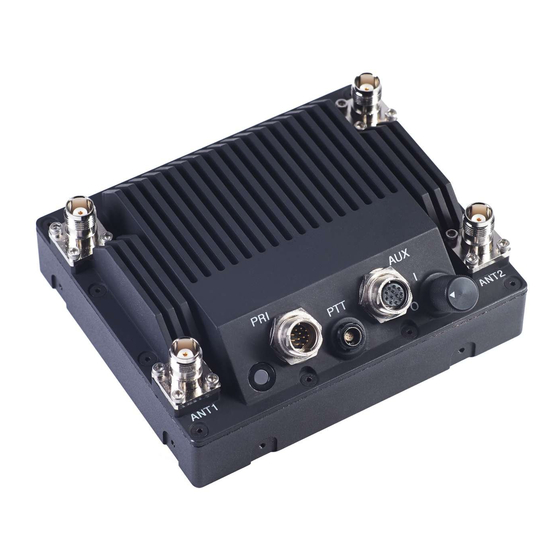
Page 17: Streamcaster Hardware Overview
• Green – Radio is wirelessly connected to at least one other radio • Flashing Red – Spectrum Scan in Progress • Flashing Red – Radio has recovered from a bad state and has reverted to factory default settings. Page 16 10017C000 Silvus Technologies Confidential... - Page 18 LED will rapidly flash green while new settings are being applied. LED will resume normal indication after settings have been applied. Power (9-20V), Ethernet, and Serial Port Connector [ODU GK0YAR-P10UC00-000L] Push-to-Talk (PTT) Connector [ODU GKCWAM-P07UB00-000L] AUX Connector [ODU GK0YCR-P10UC00-000L] Power Switch [15-Position Rotating] Page 17 10017C000 Silvus Technologies Confidential...
-
Page 19: Sc4200E
• Green – Radio is wirelessly connected to at least one other radio • Flashing Red – Spectrum Scan in Progress • Flashing Red – Radio has recovered from a bad state and has reverted to factory default settings. Page 18 10017C000 Silvus Technologies Confidential... - Page 20 • Rapid Flashing Green – When the multi position switch is rotate to a new position, LED will rapidly flash green while new settings are being applied. LED will resume normal indication after settings have been applied. Push-to-Talk (PTT) Connector [ODU GKCWAM-P07UB00-000L] AUX Connector [ODU GK0YCR-P10UC00-000L] Page 19 10017C000 Silvus Technologies Confidential...
-
Page 21: Sc4400
• Rapid Flashing Red for 1 second – The battery is less than or equal to 20%. LED will blink red rapidly for 1 second then go back to normal. This will repeat every 5 seconds. Page 20 10017C000 Silvus Technologies Confidential... - Page 22 LED will rapidly flash green while new settings are being applied. LED will resume normal indication after settings have been applied. Power (9-20V), Ethernet, and Serial Port Connector [Hirose LF10WBRB-12PD] Push-to-Talk (PTT) Connector [ODU GKCWAM-P07UB00-000L] AUX Connector [Hirose LF10WBRB-12SD] Power Switch [2-Position Rotating] Page 21 10017C000 Silvus Technologies Confidential...
-
Page 23: Sc4200
• Rapid Flashing Red for 1 second – The battery is less than or equal to 20%. LED will blink red rapidly for 1 second then go back to normal. This will repeat every 5 seconds. Page 22 10017C000 Silvus Technologies Confidential... - Page 24 • Rapid Flashing Green – When the multi position switch is rotate to a new position, LED will rapidly flash green while new settings are being applied. LED will resume normal indication after settings have been applied. Push-to-Talk (PTT) Connector [ODU GKCWAM-P07UB00-000L] AUX Connector [Hirose LF10WBRB-12SD] Page 23 10017C000 Silvus Technologies Confidential...
-
Page 25: Sc3822
• Green – Radio is wirelessly connected to at least one other radio • Flashing Red – Radio has recovered from a bad state and has reverted to factory default settings. Power (9-32 VDC), Ethernet, and Serial Port connector [Hirose LF10WBRB-12PD] Page 24 10017C000 Silvus Technologies Confidential... -
Page 26: Sc3500/Sc3800
• Orange – Radio is fully booted but not wirelessly connected to any other radio • Green – Radio is wirelessly connected to at least one other radio • Flashing Red – Radio has recovered from a bad state and has reverted to factory default settings Power Switch Page 25 10017C000 Silvus Technologies Confidential... -
Page 27: Sc3500/Sc3800 With Ext Connector (Pa Faceplate Option)
• Orange – Radio is fully booted but not wirelessly connected to any other radio • Green – Radio is wirelessly connected to at least one other radio • Flashing Red – Radio has recovered from a bad state and has reverted to factory default settings Page 26 10017C000 Silvus Technologies Confidential... -
Page 28: Connector Pinouts
Signal (GK0YAR-P10UC00-000L) (EN3C2F16X) 5V OUT (For External GPS Puck) GND IN VCC IN ETH0_MX2N ETH0_MX2P ETH0_MX1P RS232_RXD RS232_TXD ETH0_MX1N Table 2 SC4400E Power/Ethernet/Serial Connector Pinout Figure 6 SC4400E Power (Optional)/Serial/Ethernet Pinout Diagram (Cable Side) Page 27 10017C000 Silvus Technologies Confidential... -
Page 29: Table 3 Sc4400E Serial And Gps Pinout
StreamCaster MIMO Radio User Manual 4/30/19 SC4400E RS-232 Pinout RS-232 (DB9) Signal Switchcraft Pinout 5V OUT Ground Table 3 SC4400E Serial and GPS Pinout Figure 8 Switchcraft connector on Primary/Power cable Page 28 10017C000 Silvus Technologies Confidential... -
Page 30: Table 4 Sc4400E Usb/Gpio Connector Pinout (Usb1 Is Usb 2.0 Otg, Usb2 Is Usb 2.0 Host Mode Only)
USB0_VBUS GPIO1 (BDA control) USB0_D+ USB0_D- USB1_ID USB1_D+ Table 4 SC4400E USB/GPIO Connector Pinout (USB1 is USB 2.0 OTG, USB2 is USB 2.0 Host Mode Only) Figure 9 SC4400E AUX Pinout Diagram (Cable Side) Page 29 10017C000 Silvus Technologies Confidential... -
Page 31: Figure 7 Sc4400E Ptt Pinout Diagram (Cable Side)
Enclosure PTT Connector Signal (ODU GKCWAM-P07UB00-000L) RESERVED (Do Not Connect) RESERVED (Do Not Connect) AUDIO_GND SPEAKER_OUT MIC_IN RESERVED (Do Not Connect) Table 5 SC4400E PTT Connector Pinout Figure 7 SC4400E PTT Pinout Diagram (Cable Side) Page 30 10017C000 Silvus Technologies Confidential... -
Page 32: Sc4200E Pinouts
Signal (GK0YAR-P10UC00-000L) (EN3C2F16X) 5V OUT (For External GPS Puck) GND IN VCC IN ETH0_MX2N ETH0_MX2P ETH0_MX1P RS232_RXD RS232_TXD ETH0_MX1N Table 6 SC4200E Power/Ethernet/Serial Connector Pinout Figure 8 SC4200E Power (Optional)/Serial/Ethernet Pinout Diagram (Cable Side) Page 31 10017C000 Silvus Technologies Confidential... -
Page 33: Table 7 Sc4200E Serial And Gps Pinout
StreamCaster MIMO Radio User Manual 4/30/19 SC4200E RS-232 Pinout RS-232 (DB9) Signal Switchcraft Pinout 5V OUT Ground Table 7 SC4200E Serial and GPS Pinout Figure 8 Switchcraft connector on Primary/Power cable Page 32 10017C000 Silvus Technologies Confidential... -
Page 34: Table 8 Sc4200E Usb/Gpio Connector Pinout (Usb1 Is Usb 2.0 Otg, Usb2 Is Usb 2.0 Host Mode Only)
USB0_VBUS GPIO1 (BDA control) USB0_D+ USB0_D- USB1_ID USB1_D+ Table 8 SC4200E USB/GPIO Connector Pinout (USB1 is USB 2.0 OTG, USB2 is USB 2.0 Host Mode Only) Figure 9 SC4200E AUX Pinout Diagram (Cable Side) Page 33 10017C000 Silvus Technologies Confidential... -
Page 35: Figure 9 Sc4200E Ptt Pinout Diagram (Cable Side)
Enclosure PTT Connector Signal (ODU GKCWAM-P07UB00-000L) RESERVED (Do Not Connect) RESERVED (Do Not Connect) AUDIO_GND SPEAKER_OUT MIC_IN RESERVED (Do Not Connect) Table 9 SC4200E PTT Connector Pinout Figure 9 SC4200E PTT Pinout Diagram (Cable Side) Page 34 10017C000 Silvus Technologies Confidential... -
Page 36: Sc4400 Pinouts
RS232_TXD RS232_GND 100-Base T ETH0 M1N Table 10 SC4400 Power/Ethernet/Serial Connector Pinout SC4400 RS-232 and PS/2 (GPS) Pinout RS-232 PS/2 (GPS) Signal Switchcraft Pinout 5V OUT Ground Table 11 SC4400 Serial and GPS Pinout Page 35 10017C000 Silvus Technologies Confidential... -
Page 37: Figure 10 Sc4400 Power (Optional)/Serial/Ethernet Pinout Diagram (Cable Side)
StreamCaster MIMO Radio User Manual 4/30/19 Figure 10 SC4400 Power (Optional)/Serial/Ethernet Pinout Diagram (Cable Side) Page 36 10017C000 Silvus Technologies Confidential... -
Page 38: Figure 11 Sc4400 Aux Pinout Diagram (Cable Side)
Purple USB1_D- Reserved (DNC) B/W striped Pink Blue USB1_VBUS USB2_D- Serial Ground USB2_GND USB1_D+ Green Orange Yellow USB2_D+ USB2_VBUS Ext PA Control SC4400 USB / GPIO Figure 11 SC4400 AUX Pinout Diagram (Cable Side) Page 37 10017C000 Silvus Technologies Confidential... -
Page 39: Figure 12 Sc4400 Ptt Pinout Diagram (Cable Side)
Enclosure PTT Connector Signal (ODU GKCWAM-P07UB00-000L) RESERVED (Do Not Connect) RESERVED (Do Not Connect) AUDIO_GND SPEAKER_OUT MIC_IN RESERVED (Do Not Connect) Table 13 SC4400 PTT Connector Pinout Figure 12 SC4400 PTT Pinout Diagram (Cable Side) Page 38 10017C000 Silvus Technologies Confidential... -
Page 40: Sc4200 Pinouts
RS232_TXD RS232_GND 100-Base T ETH0 M1N Table 14 SC4200 Power/Ethernet/Serial Connector Pinout SC4200 RS-232 and PS/2 (GPS) Pinout RS-232 PS/2 (GPS) Signal Switchcraft Pinout 5V OUT Ground Table 15 SC4200 Serial and GPS Pinout Page 39 10017C000 Silvus Technologies Confidential... -
Page 41: Figure 13 Sc4200 Power (Optional)/Serial/Ethernet Pinout Diagram (Cable Side)
DC Power 9 – 20 V (EB Version Only) DC Power 9 – 20 V (EB Version Only) Power SC4200 Ethernet Power / Ethernet / Serial Serial Figure 13 SC4200 Power (Optional)/Serial/Ethernet Pinout Diagram (Cable Side) Page 40 10017C000 Silvus Technologies Confidential... -
Page 42: Figure 14 Sc4200 Aux Pinout Diagram (Cable Side)
Purple USB1_D- Reserved (DNC) B/W striped Pink Blue USB1_VBUS USB2_D- Serial Ground USB2_GND USB1_D+ Orange Green Yellow USB2_D+ USB2_VBUS Ext PA Control SC4200 USB / GPIO Figure 14 SC4200 AUX Pinout Diagram (Cable Side) Page 41 10017C000 Silvus Technologies Confidential... -
Page 43: Figure 15 Sc4200 Ptt Pinout Diagram (Cable Side)
Enclosure PTT Connector Signal (ODU GKCWAM-P07UB00-000L) RESERVED (Do Not Connect) RESERVED (Do Not Connect) AUDIO_GND SPEAKER_OUT MIC_IN RESERVED (Do Not Connect) Table 17 SC4200 PTT Connector Pinout Figure 15 SC4200 PTT Pinout Diagram (Cable Side) Page 42 10017C000 Silvus Technologies Confidential... -
Page 44: Sc3822 Pinouts
Table 18 SC3822 Power/Ethernet/Serial Connector Pinout SC3822 RS-232 and PS/2 (GPS) Pinout RS-232 PS/2 (GPS) Signal Switchcraft Pinout 3.3V (5V on Rev. D Digital and Newer) Ground Table 19 SC3822 Serial and GPS Pinout Page 43 10017C000 Silvus Technologies Confidential... -
Page 45: Figure 16 Sc3822 Power/Serial/Ethernet Pinout Diagram (Cable Side)
Serial Ground Green Orange Yellow DC Power 9 – 32 V DC Power 9 – 32 V SC3822 Power Ethernet Power / Ethernet / Serial Serial Figure 16 SC3822 Power/Serial/Ethernet Pinout Diagram (Cable Side) Page 44 10017C000 Silvus Technologies Confidential... -
Page 46: Figure 17 Sc3822 Usb/Gpio Pinout Diagram (Cable Side)
USB_D+ GPIO4 Table 20 SC3822 USB/GPIO Connector Pinout USB_Ground USB_Sense USB_Data- 3.3V USB_Data+ GPIO4 USB_5V GPIO3 GPIO Black/White GPIO1 (PA GPIO2 Enable 3.3V) SC 3822 USB/GPIO Figure 17 SC3822 USB/GPIO Pinout Diagram (Cable Side) Page 45 10017C000 Silvus Technologies Confidential... -
Page 47: Table 21 Sc3822 Extension Port Pinout
Wired to PS_SRST_EXT signal on FPC 1 21-54 Reserved for Testing Do Not Connect ETH1_MX4N ETH1_MX4P ETH1_MX3N ETH1_MX3P Second Gigabit Ethernet Interface ETH1_MX2N ETH1_MX2P ETH1_MX1N ETH1_MX1P 65-68 Reserved for Testing Do Not Connect Table 21 SC3822 Extension Port Pinout Page 46 10017C000 Silvus Technologies Confidential... -
Page 48: Sc3500/Sc3800 Pinouts
Table 22 SC3500/SC3800 Power Connector Pinout SC3500/3800 RS-232 and PS/2 (GPS) Pinout RS-232 PS/2 (GPS) Signal Switchcraft Pinout 3.3V (5V on Rev. E Digital and Newer) Ground LED Ground Green Table 23 SC3500/SC3800 Serial and GPS Pinout Page 47 10017C000 Silvus Technologies Confidential... -
Page 49: Figure 18 Sc3500/Sc3800 Power/Serial Pinout Diagram (Cable Side) For Gps (Top) And
StreamCaster MIMO Radio User Manual 4/30/19 Figure 18 SC3500/SC3800 Power/Serial Pinout Diagram (Cable Side) for GPS (Top) and RS-232 (Bottom) Page 48 10017C000 Silvus Technologies Confidential... -
Page 50: Figure 19 Sc3500/Sc3800 Ethernet Pinout Diagram (Cable Side)
StreamCaster MIMO Radio User Manual 4/30/19 SC3500/3800 Ethernet Connector Pinout Enclosure Pinout Signal RJ45 Pinout (801-010-07NF7-10SA) WHT/BLU WHT/BRN WHT/GRN WHT/ORG Table 24 SC3500/SC3800 Ethernet Connector Pinout Figure 19 SC3500/SC3800 Ethernet Pinout Diagram (Cable Side) Page 49 10017C000 Silvus Technologies Confidential... -
Page 51: Figure 20 Sc3500/Sc3800 Ext Pinout Diagram (Cable Side)
StreamCaster MIMO Radio User Manual 4/30/19 SC3500/3800 EXT Connector Pinout (PA Faceplate Option Only) Enclosure Pinout Signal (801-010-07NF7-25SA) PA On (+3.3V) Ground Table 25 SC3500/SC3800 EXT Connector Pinout Figure 20 SC3500/SC3800 EXT Pinout Diagram (Cable Side) Page 50 10017C000 Silvus Technologies Confidential... -
Page 52: Mechanical And Operating Specifications
Web-Based StreamScape™ Network Manager Mechanical – OEM • 4.29” x 3.3” x 0.82” Dimensions • 9.1 oz (w/ Outer Shields) Weight • SMP (m) RF Connectors (**) Must have all connectors mated with IP68+ cables/antennas Page 51 10017C000 Silvus Technologies Confidential... - Page 53 Web-Based StreamScape™ Network Manager Mechanical – OEM • 3.61” x 2.15” x 0.71” Dimensions • 4.1 oz (w/ Outer Shields) Weight • SMP (m) RF Connectors (**) Must have all connectors mated with IP68+ cables/antennas Page 52 10017C000 Silvus Technologies Confidential...
- Page 54 Web-Based StreamScape™ Network Manager Management Interface Mechanical – OEM • 4.29” x 3.3” x 0.82” Dimensions • 9.1 oz (w/ Outer Shields) Weight • SMP (m) RF Connectors (**) Must have all connectors mated with IP67+ cables/antennas Page 53 10017C000 Silvus Technologies Confidential...
- Page 55 Web-Based StreamScape™ Network Manager Management Interface Mechanical – OEM • 3.61” x 2.15” x 0.71” Dimensions • 4.1 oz (w/ Outer Shields) Weight • SMP (m) RF Connectors (**) Must have all connectors mated with IP67+ cables/antennas Page 54 10017C000 Silvus Technologies Confidential...
- Page 56 Consumption Mechanical – OEM Board Stack 24.5 W – 80% Tx Duty Cycle • 3.3” x 2.9” x 0.5” L x W x H Dimensions • 3 oz Weight • SMP (m) RF Connector Page 55 10017C000 Silvus Technologies Confidential...
- Page 57 • 12W – 22.5W (Duty Cycle and Frequency Dependent) Consumption Mechanical – OEM Board Stack 24.5 W – 80% Tx Duty Cycle • 1.9” x 5.25” x 2.9” H x L x W Dimensions Page 56 10017C000 Silvus Technologies Confidential...
- Page 58 StreamCaster MIMO Radio User Manual 4/30/19 • 8 oz Weight • SMP (m) RF Connector • Harwin M80 8-pin (m), (RS232/GPS optional) Data Connector • Harwin M80 8-pin Power Connector Page 57 10017C000 Silvus Technologies Confidential...
-
Page 59: Sc4400E Enclosure Mechanical Drawing
StreamCaster MIMO Radio User Manual 4/30/19 4.3.1 SC4400E Enclosure Mechanical Drawing Figure 21 SC4400E Mechanical Drawing (top) and Mounting Pattern (bottom) Page 58 10017C000 Silvus Technologies Confidential... -
Page 60: Sc4200E Enclosure Mechanical Drawing
StreamCaster MIMO Radio User Manual 4/30/19 4.3.2 SC4200E Enclosure Mechanical Drawing Figure 22 SC4200E Mechanical Drawing (top) and Mounting Pattern (bottom) Page 59 10017C000 Silvus Technologies Confidential... -
Page 61: Sc4400 Enclosure Mechanical Drawing
StreamCaster MIMO Radio User Manual 4/30/19 4.3.3 SC4400 Enclosure Mechanical Drawing Figure 23 SC4400 Mechanical Drawing (top) and Mounting Pattern (bottom) Page 60 10017C000 Silvus Technologies Confidential... -
Page 62: Sc4200 Enclosure Mechanical Drawing
StreamCaster MIMO Radio User Manual 4/30/19 4.3.4 SC4200 Enclosure Mechanical Drawing Figure 24 SC4200 Mechanical Drawing (top) and Mounting Pattern (bottom) Page 61 10017C000 Silvus Technologies Confidential... -
Page 63: Sc3822 Enclosure Mechanical Drawing
StreamCaster MIMO Radio User Manual 4/30/19 4.3.5 SC3822 Enclosure Mechanical Drawing Figure 25 SC3822 Mechanical Drawing (top) and Mounting Pattern (bottom) Page 62 10017C000 Silvus Technologies Confidential... -
Page 64: Sc3500/Sc3800 Phase Ii Enclosure Mounting Pattern
StreamCaster MIMO Radio User Manual 4/30/19 4.3.6 SC3500/SC3800 Phase II Enclosure Mounting Pattern Figure 26 SC3500/SC3800 Phase II Enclosure Mounting Pattern for Back of Enclosure (top) and Bottom of Enclosure (bottom) Page 63 10017C000 Silvus Technologies Confidential... -
Page 65: Sc3500/ Sc3800 Phase Iii Enclosure Mounting Pattern
StreamCaster MIMO Radio User Manual 4/30/19 4.3.7 SC3500/ SC3800 Phase III Enclosure Mounting Pattern Figure 27 SC3500/SC3800 Phase III Enclosure Mounting Pattern for Back of Enclosure (top) and Bottom of Enclosure (bottom) Page 64 10017C000 Silvus Technologies Confidential... -
Page 66: Sc4400E Specifications
Federal S (225) 2200-2300 S Band (235) 2200-2500 2.4GHz ISM (245) 2400-2500 (All bands listed in MHz) Note: If band of interest is not listed, please contact a sales representative Footnote: (*) in development Page 65 10017C000 Silvus Technologies Confidential... -
Page 67: Sc4200E Specifications
Federal S (225) 2200-2300 S Band (235) 2200-2500 2.4GHz ISM (245) 2400-2500 (All bands listed in MHz) Note: If band of interest is not listed, please contact a sales representative Footnote: (*) in development Page 66 10017C000 Silvus Technologies Confidential... - Page 68 4 Ohm to 16 Ohm • Recommended Speaker Impedance (Headset) 75 Ohm to 300 Ohm • Recommended MIC impedance <= 1K Ohm • Peak Speaker Output Voltage 5.5V • Absolute MIC Input Voltage 3.3V Page 67 10017C000 Silvus Technologies Confidential...
-
Page 69: Sc4400 Specifications
5.8GHz ISM (580) 5725-5875 S Band (235) 2200-2500 2.4GHz ISM (245) 2400-2500 (All bands listed in MHz) Note: If band of interest is not listed, please contact a sales representative Footnote: (*) in development Page 68 10017C000 Silvus Technologies Confidential... -
Page 70: Sc4200 Specifications
5.8GHz ISM (580) 5725-5875 S Band (235) 2200-2500 2.4GHz ISM (245) 2400-2500 (All bands listed in MHz) Note: If band of interest is not listed, please contact a sales representative Footnote: (*) in development Page 69 10017C000 Silvus Technologies Confidential... - Page 71 4 Ohm to 16 Ohm • Recommended Speaker Impedance (Headset) 75 Ohm to 300 Ohm • Recommended MIC impedance <= 1K Ohm • Peak Speaker Output Voltage 5.5V • Absolute MIC Input Voltage 3.3V Page 70 10017C000 Silvus Technologies Confidential...
-
Page 72: Sc3822 Specifications
ISM 900 902-928 High C Band 4700-5000 L Band 1350-1390 5.2GHz ISM 5150-5250 Broadcast A 1980-2200 5.8GHz ISM 5727-5852 Broadcast B 2025-2110 Federal ‘S’ 2200-2300 Federal ‘S’ + 2200-2500 2.4GHZ ISM Footnote: (*) in development Page 71 10017C000 Silvus Technologies Confidential... -
Page 73: Sc3500 Specifications
2.400 – 2.500 GHz 4.940 – 5.875 GHz Frequency Code ‘245540’ • 2.400 – 2.500 GHz 5.150 – 5.875 GHz Frequency Code ‘245551’ • • 2.417 – 2.457 GHz 5.735 – 5.840 GHz Frequency Code ‘243578’ • Page 72 10017C000 Silvus Technologies Confidential... -
Page 74: Sc3800 Specifications
High C Band 4700-5000 L Band 1350-1390 5.2GHz ISM 5150-5250 Broadcast A 1980-2200 5.8GHz ISM 5727-5852 Broadcast B 2025-2110 Federal ‘S’ 2200-2300 ISM2400 2400-2483 Federal ‘S’ + 2.4GHZ ISM 2200-2500 Footnote: (*) in development Page 73 10017C000 Silvus Technologies Confidential... -
Page 75: Web Interface
This page is used to set basic configurations. A brief description of each parameter is given below. • Frequency: This defines the frequency of the signal. There is a drop-down menu for frequency selection. The frequency choices will vary depending on the StreamCaster Page 74 10017C000 Silvus Technologies Confidential... - Page 76 • Apply: Apply the new values. Values will change back to the default setting after reboot. • Save and Apply: Apply the new values and set the new values as the default. Page 75 10017C000 Silvus Technologies Confidential...
-
Page 77: Advanced Configuration
Fragmentation Threshold: Allows user to determine the minimum over-the-air packet size in bytes. Smaller packet size can improve performance in high mobility while a larger packet size will allow for more throughput. (1600 bytes default). Page 76 10017C000 Silvus Technologies Confidential... - Page 78 When set to ‘Extended Auto – GI’, the radio will choose between the regular GI, and the user specified longer GI (Cyclic Prefix Length in the next setting) depending on channel conditions. • Beamforming (SC4200/SC4400 Only): Enable or disable TX Beamforming (Up to 2X increase in range when enabled) Page 77 10017C000 Silvus Technologies Confidential...
-
Page 79: Table 26 Mcs Vs. Sensitivity Chart (5Mhz Bandwidth)
4.12 QPSK 3/4 9.75 6.18 16-QAM 1/2 8.25 16-QAM 3/4 19.5 12.38 64 QAM 2/3 16.21 64 QAM 3/4 29.25 17.62 64 QAM 5/6 32.5 18.94 Table 26 MCS vs. Sensitivity Chart (5MHz Bandwidth)* Page 78 10017C000 Silvus Technologies Confidential... -
Page 80: Table 27 Mcs Vs. Sensitivity Chart (10Mhz Bandwidth)
16-QAM 3/4 57.04 64 QAM 2/3 75.00 64 QAM 3/4 85.00 64 QAM 5/6 94.00 Table 28 MCS vs. Sensitivity Chart (20MHz Bandwidth)* *Sensitivity numbers reflect “typical” values. Actual sensitivity will vary by band. Page 79 10017C000 Silvus Technologies Confidential... -
Page 81: Lan/Wifi Configuration
StreamCaster MIMO Radio User Manual 4/30/19 5.1.3 LAN/WIFI Configuration Figure 30 LAN/WIFI Configuration Page Page 80 10017C000 Silvus Technologies Confidential... - Page 82 ./supernode -l 9000 -v Server will be running on port 9000. • VPN Server IP: IP Address of N2N VPN Server • VPN Server Port: Port that the N2N VPN server is configured to listen on. Page 81 10017C000 Silvus Technologies Confidential...
- Page 83 4,5,6,7. Any combination of the above is allowed. WiFi Settings: Note: Use of this feature requires a Silvus USB-WiFi adapter. The WiFi settings will only display if the WiFi dongle is attached to the radio’s USB port before it is powered on.
- Page 84 This is the simplest mode as all data is transparent and at layer 2. NAT mode puts the WiFi wireless traffic on a LAN, and the rest of the Silvus mesh network on a WAN. In effect, this means that a device connected wirelessly via the NAT AP will be able to find any device in the larger mesh network, but not vice versa.
-
Page 85: Multicast
“+”. Traffic may be prevented from reaching a radio by adding postfix “-”. (e.g. 224.50.50.50 1234, 1235-, 1236+) If receiver_id is -1, it will stop multicast traffic for this group. Page 84 10017C000 Silvus Technologies Confidential... - Page 86 Higher latencies are better since the low density parity check code can generate more robust codes resulting in better error correction on the receiver. Amount of Error Correction is the amount of additional error correction packets sent along with the data packets. Page 85 10017C000 Silvus Technologies Confidential...
-
Page 87: Quality Of Service (Qos) #Qos
StreamCaster MIMO Radio User Manual 4/30/19 5.1.5 Quality of Service (QoS) #QoS Figure 32 Quality of Service (QoS) Configuration Page Page 86 10017C000 Silvus Technologies Confidential... - Page 88 The receiver timeout is the length of time the receiver waits for out-of-order packets before giving up and delivering the data it has in its buffer. This is similar in concept to Page 87 10017C000 Silvus Technologies Confidential...
- Page 89 Fair Queuing with Control Delay (FQ_CoDeL) scheduling algorithm. The feature is applicable to IPv4 and IPv6 untagged and tagged packets. Fragmented packets are not supported. Detailed below is the DSCP to queue/priority mapping. Page 88 10017C000 Silvus Technologies Confidential...
- Page 90 Admin State – Enables and disables the scheduler. Minimum Bandwidth Percent – Sets the minimum bandwidth guarantee for the queues as a percentage of the link rate. The sum of the minimum bandwidth guarantees cannot exceed 100% of the link rate. Page 89 10017C000 Silvus Technologies Confidential...
-
Page 91: Serial/Usb Setup
TCP to server on local subnet. It will expect data in GPSd format. If GPS information is pushed to the radio via Ethernet, the radio will listen on specified port and expect GPS data as NMEA Formatted UDP packets. Page 90 10017C000 Silvus Technologies Confidential... - Page 92 USB Status (3822/4200/4400): The USB port on the 3822/4200/4400 can auto-detect whether the connected device is a USB host or client device. The USB cable should not be unplugged while the radio is running. Page 91 10017C000 Silvus Technologies Confidential...
-
Page 93: Node Diagnostics
This setting allows the users to report the RSSI values every few milliseconds base on users setting. LED Configuration: This setting allows the user to disable or enable the LED on the faceplate of the radio. Page 92 10017C000 Silvus Technologies Confidential... - Page 94 StreamCaster MIMO Radio User Manual 4/30/19 Voltage Monitor: Radios built on or after Jan 1, 2015 have the ability to monitor the input voltage, displayed here. Page 93 10017C000 Silvus Technologies Confidential...
-
Page 95: Bda Support
• Maximum PA Output Power Per Channel (dBm): Enter the maximum output power for each PA. • Apply: Apply the new values but does not save them to flash. • Save and Apply: Save the new values to flash and apply. Page 94 10017C000 Silvus Technologies Confidential... -
Page 96: Build Information
Build Information Figure 36 Build Information The ‘Build Information’ page provides information about the hardware and firmware loaded onto the radio, as well as the changelog of the currently loaded and past firmware revisions. Page 95 10017C000 Silvus Technologies Confidential... -
Page 97: Security
Update the web login password to something other than “HelloWorld” o Create new SSH keys and HTTPS certificate. o Update encryption key or click “Generate Encryption Key” and save. • Encryption Key: Set an encryption key if encryption is enabled. Page 96 10017C000 Silvus Technologies Confidential... -
Page 98: Figure 38 Security (Upgrade)
The firmware can be upgraded by simply choosing the upgrade image from your desktop and uploading it to the radio. This field can be used to upgrade the radio root file system, linux kernel, or uboot. Page 97 10017C000 Silvus Technologies Confidential... -
Page 99: Figure 39 Security (Upgrade Network)
Users can simply choose the appropriate firmware file for the corresponding radio models to apply the upgrade to all the radios in the network. Currently, this feature is not available in HTTPS mode. License: Figure 40 Security (License) Page 98 10017C000 Silvus Technologies Confidential... -
Page 100: Figure 41 Security (Factory Reset)
StreamCaster MIMO Radio User Manual 4/30/19 Features such as encryption levels and frequency ranges can be enabled by license keys obtained from Silvus. New license keys can be uploaded to the radio on this page. Factory Reset: Figure 41 Security (Factory Reset) •... -
Page 101: Figure 42 Security (Setting Profile)
• Save Current Settings: Store the current settings on to the radio for future access. Note that the FIPS mode setting is not saved in the profile. You must manually enable/disable it after applying the profile. Page 100 10017C000 Silvus Technologies Confidential... -
Page 102: Figure 43 (Key Management)
A common way this is done on a computer is through the command `ssh-keygen -t ecdsa -b 521`. You will need to do this for each machine that wants to SSH into the radio, or you can share a single key pair amongst machines. Page 101 10017C000 Silvus Technologies Confidential... -
Page 103: Figure 44 (Chrome Browser Warning)
Then create a X.509 certificate and append your private key to it. Copy the certificate text to the “Add a HTTPS Certificate” section, then click “Add Certificate and Save.” Figure 44 (Chrome Browser Warning) Page 102 10017C000 Silvus Technologies Confidential... -
Page 104: Ptt (Sc4400/Sc4200 Only)
The PTT page can be used to configure talk groups (Multicast Groups) and speaker/mic settings for PTT enabled radios. Radios will only communicate with other radios that are subscribed to the same ‘Multicast Group’. Radios can be active in multiple talk groups. Page 103 10017C000 Silvus Technologies Confidential... - Page 105 SNR level to the user-specified HQ node. If the level transitions option is enabled, the notification will be played automatically when the SNR crosses the specified thresholds. The SNR thresholds can be set by first choosing the number of levels desired, and then moving the sliders accordingly. Page 104 10017C000 Silvus Technologies Confidential...
-
Page 106: Spectrum Scan
5.1.12 Spectrum Scan Figure 46 Spectrum Scan Results The spectrum scan feature turns a Silvus network of radios into a distributed spectrum analyzer. When a scan is initiated, each selected radio in the network will go offline, perform a scan of the requested range, and report back. -
Page 107: Figure 47 Spectrum Scan Settings
Center Frequency – Specify the center frequency of the scan. Span – Specify the span of the scan, centered on the center frequency. (e.g. Center freq of 2450MHz and span of 100MHz will scan 2400-2500MHz). A large span will take longer to complete. Page 106 10017C000 Silvus Technologies Confidential... -
Page 108: Figure 48 Zero Span Settings
In the Zero Span mode, the radio will provide a plot of the power measured in a 20MHz bandwidth across time. Zero Span can only be conducted on one radio in the network at a time. Other radios in the network will continue to operate and transmit so a zero span Page 107 10017C000 Silvus Technologies Confidential... -
Page 109: Figure 49 Zero Span Results
Duration – Duration of each scan. A longer duration will provide better accuracy but will take longer to complete. Approximated time for scan – Approximate time that the network will be down for the scan to complete. Figure 49 Zero Span Results Page 108 10017C000 Silvus Technologies Confidential... -
Page 110: Mps (Multi-Position Switch)
Basic Tab, PTT/Audio Tab), position 1 will be updated with those results. The green highlight shows the current position of the physical switch. If the radio boots up in position “Z,” MPS will be disabled until the radio is rebooted in another position. Page 109 10017C000 Silvus Technologies Confidential... -
Page 111: Admin Settings
Streamscape will require a username and password as shown below. To change the password, click “Change Password,” then select the username whose password will change, type the Admin password, then type the new password. Figure 52 Login Page 110 10017C000 Silvus Technologies Confidential... -
Page 112: Figure 53 Reset Password
If a user forgets the password, click “Forgot Password.” They can reset the password using a USB flash drive and a password reset key provided by Silvus. On the USB, the password reset key file must be called reset_pass.txt.signed. Note that since the SC3500 and SC3800 do not have USB ports, you will not be able to set a password for these radios. -
Page 113: Streamscape Network Manager
The graphical interface network map, shown in Figure 44, allows users to quickly and effortlessly view the network topology and configure key parameters of the network. For ease of use, the Silvus StreamScape utility is designed to be accessible from a Firefox or Chrome web browser. 5.2.1... -
Page 114: Figure 55 Example Network Topology
4/30/19 • Route Health – The Silvus StreamScape Utility will alert the user when too many packets are being routed through a single node. In such cases, a node will change from green to yellow to red as the packet queue increases (see ‘1132_4.108’ and ‘1131_4.107’in Figure 55). This will allow the user to recognize the issue and rearrange the network accordingly. -
Page 115: Figure 56 Routing Path
The saved labels can also be cleared back to the defaults by clicking ‘Clear Labels in Flash’. The node labels set in one radio can also be broadcasted to other radios in the network by clicking the ‘Broadcast Node Labels’ button. Page 114 10017C000 Silvus Technologies Confidential... -
Page 116: Figure 57 Custom Node Naming
MAC: MAC address of the node. o Connections: Number of direct connections to node. Each directly connected node is listed in the following format: <Node Name> <RX SNR> <TX MCS> <Pkts in TX Queue> <Num. of Spatial Streams> Page 115 10017C000 Silvus Technologies Confidential... - Page 117 Fragmentation Threshold: Chosen fragmentation threshold. o Virtual IP: Secondary IP address of node (0 if none set). o MCS Mode: Transmit MCS of node. o Variable GI mode: The variable GI mode setting for this node. Page 116 10017C000 Silvus Technologies Confidential...
- Page 118 Input Dropped Rate: Total data rate dropped by the radio o Forwarded Unicast Rate: Total data rate forwarded by the radio as Unicast o Forwarded Broadcast/Multicast Rate: Total data rate forwarded by the radio as Multicast Page 117 10017C000 Silvus Technologies Confidential...
-
Page 119: Figure 59 Individual Node Characteristics
This is estimated based on the current MCS used for transmission. o Queue Size: Number of packets in TX Queue in each direction. o NSS: Number of Spatial Streams in each direction. o Air Time: Percentage of air time used in each direction Page 118 10017C000 Silvus Technologies Confidential... -
Page 120: Figure 60 Link Characteristics
Datagram Size: Size of the datagram o Effective Bandwidth: The actual network load. o Jitter: The variation in delays in the received packet. o Lost/Total Datagrams: The amount of packets lost vs total packets sent Page 119 10017C000 Silvus Technologies Confidential... -
Page 121: Figure 61 Iperf Function Within Gui
StreamCaster MIMO Radio User Manual 4/30/19 Figure 61 iPerf Function within GUI Page 120 10017C000 Silvus Technologies Confidential... -
Page 122: Figure 62 Table View
The table view tab shows all the statistics and setting profiles in table view. Users can select what is needed through the drop-down menu on the upper left side. The dropdown is shown in Figure 63 Table View (Settings) Page 121 10017C000 Silvus Technologies Confidential... -
Page 123: Figure 63 Table View (Settings)
StreamCaster MIMO Radio User Manual 4/30/19 Figure 63 Table View (Settings) Page 122 10017C000 Silvus Technologies Confidential... -
Page 124: Network-Wide Setup
A list of all nodes will appear on the right with a check box next to each node. This box will be checked off as each node receives the update. Figure 64 Network-wide Setup Page 123 10017C000 Silvus Technologies Confidential... -
Page 125: Per-Node Setup
3 files (uboot, kernel, rootfs) for upgrade. A radio reboot will be required after update before the changes take effect. Figure 65 Per-Node Setup Page 124 10017C000 Silvus Technologies Confidential... -
Page 126: Map Overlay
For convenience, a small copy of the network topology is displayed on the right-hand side of the page. This allows users to clearly view the network characteristics in instances where nodes are physically close to one another and difficult to distinguish on the map overlay. Page 125 10017C000 Silvus Technologies Confidential... -
Page 127: Figure 67 Google Maps
For instructions to Download OpenStreet Maps into the radio, see section 5.2.5.2. OpenStreet Maps Silvus is a version of OpensStreet maps which is hosted on Silvus’ servers in case of an interruption in service with OpenStreet Maps. The Silvus maps currently only cover the United States. -
Page 128: Figure 68 Offline Map Image
Once entered, click upload and there will now be a 4 option when clicking the ‘+’ at the top left of the map overlay. Page 127 10017C000 Silvus Technologies Confidential... - Page 129 Users should be careful in using this feature since it may take some time and will use up the radio’s available memory. For reference, a radius of ~3000m will use approximately 5 percent of the total memory. Page 128 10017C000 Silvus Technologies Confidential...
-
Page 130: Figure 69 Placing Nodes On The Map
GPS connectivity, the user can easily place the node on the map by right clicking on the desired location on the map and choosing which node to place there. These values will be ignored if GPS coordinates are available via a GPS module. Page 129 10017C000 Silvus Technologies Confidential... -
Page 131: Figure 70 Cursor On Target Settings
• CoT Current Time (UTC): Time stamp of the time • CoT Stale Time (Seconds): Data outside of this time window becomes invalid • CoT Type: The event type of the target Page 130 10017C000 Silvus Technologies Confidential... -
Page 132: Fips Mode
Potential User Errors 6.1.1 o Do not use the same encryption key you were using in non FIPS mode because these may have been broadcasted in plain text. Generate new ones once in FIPS mode. Page 131 10017C000 Silvus Technologies Confidential... -
Page 133: List Of Security Parameters
SSH access to the radios. These key pairs are used instead of passwords since they are more secure. o TLS Host Key (also called HTTPS Certificate): This certificate is used to establish a HTTPS connection. The underlying elliptic curve keys can be either secp256r1, secp384r1, or secp521r1. Page 132 10017C000 Silvus Technologies Confidential... -
Page 134: Wired Backbone
All video feeds are sent back and displayed at the HQ. To conserve air bandwidth and possible interference to other users, we want video data to go through the high-speed LAN backbone as much as possible. The below diagram shows the scenario. Page 133 10017C000 Silvus Technologies Confidential... -
Page 135: Wan Backbone With Roaming
WAN Backbone with Roaming The WAN backbone feature allows the wireless mesh network to extend over Internet links. Multiple geographically separate “sites” can be connected into one single layer 2 network as long as each site has Page 134 10017C000 Silvus Technologies Confidential... -
Page 136: Implementation
Note that the WAN and LAN backbone are complementary features. E.g. at the HQ, multiple radios can be connected to a LAN backbone so that any approaching soldier or group has a direct line of sight wireless connection to the HQ. Page 135 10017C000 Silvus Technologies Confidential... -
Page 137: Figure 72 Wan Backbone Example
StreamCaster MIMO Radio User Manual 4/30/19 Figure 72 WAN Backbone Example Page 136 10017C000 Silvus Technologies Confidential... -
Page 138: Custom Frequency Plan
Remove Frequency: Remove the currently selected frequency. • Custom Frequencies Plan Upload: Upload the selected frequency plan. The second method requires accessing the hidden Custom Frequency Plan page. Note radios on older firmware only support this method. Page 137 10017C000 Silvus Technologies Confidential... - Page 139 The interface will allow an upload of a custom frequency plan file which should be in the following format: "type": "custom_frequency_plan", "name": "cfp_example", "description": "CFP Example", "frequencies": [ "2412", "2417", "2422", "2427", "2432", "2437", "2442", "2447", "2452", "2457", "2462", "2467", "2472", "5745", "5765", "5785", "5805", "5825" Page 138 10017C000 Silvus Technologies Confidential...
- Page 140 Once installed, the Custom Frequency Plan will be cross-checked with hardware capability and the licensed frequency range previously installed on the radio. The Custom Frequency Plan will only change what is displayed. It will not give new frequencies that are previously out of licensed range. Page 139 10017C000 Silvus Technologies Confidential...
-
Page 141: Streaming Response
The empty string listed above has a NULL character and has length 1. Any length number in the streaming report includes the NULL character • A UDP packet may contain more than one report. • The UDP packets have a maximum size of 1400 bytes. Page 140 10017C000 Silvus Technologies Confidential... -
Page 142: Rssi And Noise Floor Reporting
They cannot be directly compared to the raw signal and noise values. To obtain an SNR from these values the user needs to run the below formula on these values: X = sync signal power; Y = sync noise power; Page 141 10017C000 Silvus Technologies Confidential... -
Page 143: Table 31 Sample Rssi Report
13 ffffff8a 0 5 20 2d 32 38 0 13 ffffff8b 0 5 20 2d 36 36 0 13 ffffff8c 0 5 2d 31 39 30 0 13 ffffff8d 0 a 20 20 38 36 30 34 35 36 38 0 Page 142 10017C000 Silvus Technologies Confidential... - Page 144 StreamCaster MIMO Radio User Manual 4/30/19 13 ffffff8e 0 a 20 20 38 38 36 31 33 32 32 0 13 ffffff8f 0 5 31 30 32 35 0 0 1 0 1 0 Page 143 10017C000 Silvus Technologies Confidential...
-
Page 145: Temperature Reporting
Current Temperature on the radio. Integer Maximum Temperature reached on the radio after last booting. Integer Overheat Count: number of times the radio temperature has exceeded temp_reporting_max_threshold. Empty string "" End of report Table 32 Temperature Reporting Format Page 144 10017C000 Silvus Technologies Confidential... -
Page 146: Voltage Reporting
UNDERVOLTAGE_COUNT Number of times voltage dropped _REPORT below min threshold, as an integer string 4008 OVERVOLTAGE_COUNT_ Number of times vltage spiked above REPORT max threshold, as an integer string. Table 33 Voltage Reporting Format Page 145 10017C000 Silvus Technologies Confidential... -
Page 147: Setting Up An Iperf Test
• At the receiver side type the following in a terminal o iperf –s –u -i 1 • At the transmitter side type the following in a terminal o iperf –c receiver_laptop_ip_address –u –i 1 –b 1M –t 60 Page 146 10017C000 Silvus Technologies Confidential... -
Page 148: Precautions And Recommendations
“save and apply” operation. Partial saving of the configuration to the radio due to power interruption may disable the radio requiring reprogramming at the factory. Also, please wait for a “done” feedback at the web interface before proceeding to any other configuration changes. Page 147 10017C000 Silvus Technologies Confidential... -
Page 149: Troubleshooting
• In a long range scenario if SNR is good but link drops unexpectedly check link distance parameter and make sure that the link distance is set the same on all radios and sufficiently large enough. • Check interference levels as strong interference can result in an intermittent link. Page 148 10017C000 Silvus Technologies Confidential... -
Page 150: Fcc Notice
Maximum Output Power across Frequency Range #1: 268.64mW from 2420MHz to 2450MHz Maximum Output Power across Frequency Range #2: 329.02mW from 5760MHz to 5810MHz 13.3 FCC Identifier: N2S-SC42-245 Silvus model #: SC4210-245-BB, SC4240-245-BB Equipment Class: Digital Transmission System Page 149... -
Page 151: Fcc Identifier: N2S-Sc44-245
Maximum Output Power @ Frequency #1: 810.17mW @ 2430MHz Maximum Output Power @ Frequency #2: 795.3mW @ 2440MHz 13.4 FCC Identifier: N2S-SC44-245 Silvus model #: SC4410-235-SBST, SC4480-235-SBST Equipment Class: Digital Transmission System The following parameters must be used to be compliant to the appropriate FCC requirements: Antenna: 2.1dBi Omni Antennas (AOV2S230515) -
Page 152: Fcc Identifier: N2S-Sc44-520
Maximum Output Power @ Frequency #2: 246.52mW @ 5240MHz 13.7 FCC Identifier: N2S-SC42E-245 Silvus model #: SC4210E-245-EBEquipment Class: Digital Transmission System The following parameters must be used to be compliant to the appropriate FCC requirements: Antennas: 2.1dBi Omni Antennas (Silvus AOV2D230515) &... -
Page 153: Notes Regarding Ce Mark (Sc4200-206-Eb And Sc4400-206-Sbst Models Only)
20 cm from all persons and must not be co-located or operating in conjunction with any other antenna or transmitter. 14. Notes Regarding CE Mark (SC4200-206-EB and SC4400-206-SBST models only) The following Silvus Technologies models are declared to conform to CE Mark requirements: Silvus P/N: SC4240-206-EB, SC4480-206-SBST Relevant standards: ETSI EN 302 064 V2.1.1 (2016-09), Wireless Video Links, Harmonized Standard... - Page 154 Silvus cable assembly (SC22-PRICBL02-6) External Bandpass Filter: Microwave Filter Co. model 3813 (a filter of equivalent performance may also be used, contact Silvus Technologies customer support for more information) AC Adapter (if used): EDAC Power Electronics EA10523C-120 (this adapter is approved for indoor use...
-
Page 155: Table 34 Additional Restrictions On Band C2
StreamCaster MIMO Radio User Manual 4/30/19 Table 34 Additional Restrictions on Band C2 10017C000 Silvus Technologies Confidential Page 154... - Page 156 StreamCaster MIMO Radio User Manual 4/30/19 Page 155 10017C000 Silvus Technologies Confidential...
-
Page 157: Ised Canada Notice
Antenna types not included in this list, having a gain greater than the maximum gain indicated for that type, are strictly prohibited for use with this device. 1. Omnidirectional antenna, Silvus P/N A0VD230515, maximum antenna gain 2.1 dBi, 50 ohm 2. Omnidirectional antenna, Silvus P/N A0V4S235, maximum antenna gain 4dBi, 50 ohm This device contains license-exempt transmitter(s)/receiver(s) that comply with Innovation, Science and Economic Development Canada’s licence-exempt RSS(s). -
Page 158: Ic Statement: French
1. Omnidirectional d'onde, Silvus P/N A0VD230515, le gain max 2.1 dBi, 50 ohm 2. Omnidirectional d'onde, Silvus P/N A0V4S235, le gain max 4 dBi, 50 ohm L’émettur/récepteur exempt de licence conenu dans le présent appareil est conforme aux...
Need help?
Do you have a question about the StreamCaster SC4400E and is the answer not in the manual?
Questions and answers