
Related Manuals for Silvus StreamCaster MIMO


Summary of Contents for Silvus StreamCaster MIMO
- Page 1 StreamCaster MIMO Radio User Manual Document Number 10017C000 Version Date 3/17/2015 Silvus Technologies, Inc. 10990 Wilshire Blvd, #1500 Los Angeles, CA 90024...
- Page 2 3/17/15 Notice Silvus Technologies reserves the right to make changes to its products or discontinue any of its products or offerings without notice. Silvus warrants the performance of its products to the specifications applicable at the time of sale in accordance with Silvus’...
-
Page 3: Table Of Contents
StreamCaster MIMO Radio User Manual 3/17/15 Contents General Safety Information ........................5 Health & Safety .......................... 6 Maximum RF Power Density Limits ..................7 Introduction ............................8 StreamCaster Network .......................... 8 Hardware Overview ..........................9 StreamCaster Hardware Interface ....................9 SC3822: ............................ - Page 4 StreamCaster MIMO Radio User Manual 3/17/15 StreamScape Network Manager ....................43 Network Topology ....................... 43 5.2.1 5.2.2 Network-wide Setup and Multicast ................48 5.2.3 Per-Node Setup ......................50 5.2.4 Map Overlay ........................ 51 Wired Backbone ..........................56 LAN Backbone ......................... 56 6.1.1...
- Page 5 Figure 21 Security (License)........................40 Figure 22 Security (Factory Reset) ......................41 Figure 23 Security (Reset Password) ....................... 42 Figure 24 Silvus StreamScapeNetwork Manager .................. 43 Figure 25 Example Network Topology ....................44 Figure 26 Routing Path ..........................45 Figure 27 Custom Node Naming......................45 Figure 28 Individual Node Characteristics (Left), Link Characteristics (Right) ........
- Page 6 StreamCaster MIMO Radio User Manual 3/17/15 Figure 30 Per-Node Setup ........................50 Figure 31 Map Overlay ..........................51 Figure 32 Google Maps ..........................52 Figure 33 Offline Map Image ........................53 Figure 34 Placing Nodes on the Map ....................... 55 Figure 35 LAN Backbone Example ......................
-
Page 7: General Safety Information
Avoid standing in front of high gain antennas (such as a dish) and never look into the open end of a waveguide or cable where strong RF power may be present. Users are strongly recommended to return any equipment that requires RF servicing to Silvus Technologies. -
Page 8: Health & Safety
It is important to note that the guidelines adopted differ throughout the world and are from time-to-time re-issued with revised guidelines. For Silvus use, a maximum power density limit of 1w/m² is to be applied when calculating minimum safe working distances. -
Page 9: Maximum Rf Power Density Limits
Different power density / frequency characteristics are presented in the two documents. To avoid complexity and to avoid areas of uncertainty, Silvus recommends the use of a single power density limit across the frequency range 100 kHz to 300 GHz. The 1w/m² power density limit we recommend satisfies the most stringent of the guidelines published to date. -
Page 10: Introduction
StreamCaster radio and to also run an iperf network test. 3. StreamCaster Network Each StreamCaster MIMO radio has a fixed static IP address in the 172.20.xx.yy network. The radio operates as a network switch; the user equipment does not need to be on the same subnet as the radio during operation. -
Page 11: Hardware Overview
StreamCaster MIMO Radio User Manual 3/17/15 4. Hardware Overview StreamCaster Hardware Interface SC3822: Figure 1 StreamCaster 3822 Ruggedized Enclosure RF channels 1-2 connectors [SMA Female] USB/GPIO connector [Hirose LF10WBRB-12SD] Tri-Color Status LED (See Section 10.1 for Troubleshooting Information) Red – Radio is in the process of booting up ... -
Page 12: Sc3500/Sc3800
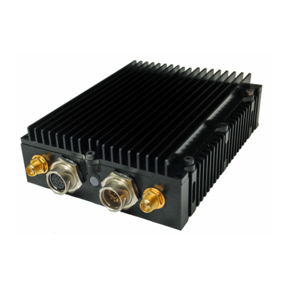
StreamCaster MIMO Radio User Manual 3/17/15 SC3500/SC3800: Figure 2 StreamCaster 3500/3800 Ruggedized Enclosure RF channels 1-4 connectors [TNC Female] Ethernet connector [Mighty-Mouse 801-010-07NF7-10SA] Power (9-20 VDC) and Serial Port connector [Mighty-Mouse 801-010-07NF7-10PA] Tri-Color Status LED (See Section 10.1 for Troubleshooting Information) ... -
Page 13: Sc3500/Sc3800 With Ext Connector (Pa Faceplate Option)
StreamCaster MIMO Radio User Manual 3/17/15 SC3500/SC3800 with EXT Connector (PA Faceplate Option): Figure 3 StreamCaster 3500/3800 Ruggedized Enclosure RF channels 1-4 connectors [TNC Female] EXT PA Connector [Mighty-Mouse 801-010-07NF7-25SA] Ethernet connector [Mighty-Mouse 801-010-07NF7-10SA] Power (9-20 VDC) and Serial Port connector [Mighty-Mouse 801-010-07NF7-10PA] Power Switch Tri-Color Status LED (See Section 10.1 for Troubleshooting Information) -
Page 14: Connector Pinouts
StreamCaster MIMO Radio User Manual 3/17/15 Connector Pinouts 4.1.1 SC3822 Pinouts SC3822 Power/Ethernet/Serial Connector Pinout Enclosure PWR/COMM Switchcraft Pinout Signal (LF10WBRB-12PD) (EN3C2F16X) 3.3V OUT GND IN GND IN VCC IN VCC IN 100-Base T ETH0 M2N 100-Base T ETH0 M2P... -
Page 15: Table 4 Sc3822 Usb/Gpio Connector Pinout
StreamCaster MIMO Radio User Manual 3/17/15 Enclosure USP/GPIO Signal (LF10WBRB-12PD) USB_GND USB_D- USB_5V GPIO1 (PA Enable 3.3V) GPIO2 GPIO3 3.3V USB_Sense USB_D+ GPIO4 Table 4 SC3822 USB/GPIO Connector Pinout SC3822 Extension Connector Pinout Pin # Signal Notes VCC_IN 9V - 36V. These pins are directly wired to the VCC_IN on FPC 1. -
Page 16: Figure 4 Sc3822 Power/Serial/Ethernet Pinout Diagram (Cable Side)
StreamCaster MIMO Radio User Manual 3/17/15 Figure 4 SC3822 Power/Serial/Ethernet Pinout Diagram (Cable Side) Page 14 10017C000 Silvus Technologies Confidential... -
Page 17: Sc3500/Sc3800 Pinouts
StreamCaster MIMO Radio User Manual 3/17/15 4.1.2 SC3500/SC3800 Pinouts SC3500/3800 Power Connector Pinout Enclosure Pinout Switchcraft Pinout Signal (801-010-07NF7-10PA) (EN3C2F16X) 12V Power Return 12V Power Return 12V Power 12V Power For Serial Comm. For Serial Comm. For Serial Comm. For Serial Comm. -
Page 18: Table 8 Sc3500/Sc3800 Ext Connector Pinout
StreamCaster MIMO Radio User Manual 3/17/15 SC3500/3800 EXT Connector Pinout (PA Faceplate Option Only) Enclosure Pinout Signal (801-010-07NF7-25SA) PA On (+3.3V) Ground LED1 (Black) LED2 (Green) LED3 (Red) Table 8 SC3500/SC3800 EXT Connector Pinout SC3500/3800 RS-232 and PS/2 (GPS) Pinout... -
Page 19: Figure 5 Sc3500/Sc3800 Power/Serial Pinout Diagram (Cable Side) For Gps (Top) And Rs-232 (Bottom)
StreamCaster MIMO Radio User Manual 3/17/15 Figure 5 SC3500/SC3800 Power/Serial Pinout Diagram (Cable Side) for GPS (Top) and RS-232 (Bottom) Page 17 10017C000 Silvus Technologies Confidential... -
Page 20: Figure 6 Sc3500/Sc3800 Ethernet Pinout Diagram (Cable Side)
StreamCaster MIMO Radio User Manual 3/17/15 Figure 6 SC3500/SC3800 Ethernet Pinout Diagram (Cable Side) Figure 7 SC3500/SC3800 EXT Pinout Diagram (Cable Side) Page 18 10017C000 Silvus Technologies Confidential... -
Page 21: Mechanical And Operating Specifications
StreamCaster MIMO Radio User Manual 3/17/15 Mechanical and Operating Specifications SC3822: Environmental Standard Temperature Extended Temperature -40° - +55° C -40° - +65° C Operating Temp. IP-67 (Dust / Immersion in water up to 1m)* IP Rating (Ingress Protection) *Must have all connectors mated and use IP67 or better cables/antennas Mechanical –... -
Page 22: Controls And Indicators
StreamCaster MIMO Radio User Manual 3/17/15 SC3500/SC3800: Environmental Standard Extended Temperature -40° - +55° C -40° - +65° C Operating Temp. IP-67 (Dust / Immersion in water up to 1m)* IP Rating (Ingress Protection) *Must have all connectors mated and use IP67 or better cables/antennas Mechanical –... -
Page 23: Sc3822 Enclosure Mechanical Drawing
StreamCaster MIMO Radio User Manual 3/17/15 4.2.1 SC3822 Enclosure Mechanical Drawing Figure 8 SC3822 Mechanical Drawing (top) and Mounting Pattern (bottom) Page 21 10017C000 Silvus Technologies Confidential... -
Page 24: Sc3500/Sc3800 Phase Ii Enclosure Mounting Pattern
StreamCaster MIMO Radio User Manual 3/17/15 4.2.2 SC3500/SC3800 Phase II Enclosure Mounting Pattern Figure 9 SC3500/SC3800 Phase II Enclosure Mounting Pattern for Back of Enclosure (top) and Bottom of Enclosure (bottom) Page 22 10017C000 Silvus Technologies Confidential... -
Page 25: Sc3500/ Sc3800 Phase Iii Enclosure Mounting Pattern
StreamCaster MIMO Radio User Manual 3/17/15 4.2.3 SC3500/ SC3800 Phase III Enclosure Mounting Pattern Figure 10 SC3500/SC3800 Phase III Enclosure Mounting Pattern for Back of Enclosure (top) and Bottom of Enclosure (bottom) Page 23 10017C000 Silvus Technologies Confidential... -
Page 26: Sc3822 Specifications
StreamCaster MIMO Radio User Manual 3/17/15 SC3822 Specifications General Waveform Mobile Networked MIMO (MN-MIMO™) Modulation BPSK, QPSK, 16-QAM, 64-QAM Channel Bandwidth 5, 10 & 20 MHz (1.25*, 2.5*) Encryption DES Standard, AES 128/256 Optional (FIPS 140-2) ... -
Page 27: Sc3500 Specifications
StreamCaster MIMO Radio User Manual 3/17/15 SC3500 Specifications General Radio Type MIMO Coded-OFDM Subcarrier Modulation BPSK, QPSK, 16-QAM, 64-QAM Channel Bandwidth 5, 10 & 20 MHz Encryption DES Standard, AES 128/256 Optional Frequency Stability 1 PPM over temp -40° - +85° C ... -
Page 28: Sc3800 Specifications
StreamCaster MIMO Radio User Manual 3/17/15 SC3800 Specifications General Radio Type MIMO Coded-OFDM Subcarrier Modulation BPSK, QPSK, 16-QAM, 64-QAM Channel Bandwidth 5, 10 & 20 MHz (1.25*, 2.5*) Encryption DES Standard, AES 128/256 Optional Frequency Stability 1 PPM over temp -40°... -
Page 29: Web Interface
StreamCaster MIMO Radio User Manual 3/17/15 5. Web Interface Getting Started Connect a laptop to the StreamCaster radio using the supplied Ethernet cable and turn on the radio. Users can type “ping <IPaddress>” in order to determine whether the radio is fully booted. - Page 30 StreamCaster MIMO Radio User Manual 3/17/15 Link Distance: Set to an approximate maximum distance between any two nodes in meters, e.g., 5000 for 5km (default). It is important to set the link distance to allow enough time for packets to propagate over the air. Failing to set the link distance to an approximate maximum distance can result in over the air collisions and a degradation of performance.
-
Page 31: Advanced Configuration
StreamCaster MIMO Radio User Manual 3/17/15 5.1.2 Advanced Configuration Figure 12 Advanced Configuration Page This page is used to set advanced configurations. A brief description of each parameter is given below. MAC Settings: Routing Beacon Period: Controls how often routing beacons are sent to other radios. A lower Routing Beacon Period results in faster reaction to topology changes. - Page 32 StreamCaster MIMO Radio User Manual 3/17/15 Burst Time: The burst time determines the maximum amount of time each node is allowed to transmit at once. A larger burst time will provide higher throughput at the cost of higher latency. On the other hand, a smaller burst time will provide less latency at the cost of less throughput.
- Page 33 StreamCaster MIMO Radio User Manual 3/17/15 Gateway: Gateway for local network to allow radio to connect to the internet VPN: For WAN wired backbone scenarios where radios from two different sites are connected via the internet, a public N2N server is needed to route the data. Here is an example of how to setup an N2N server on a server hosted by Amazon AWS running Ubuntu 12.04:...
-
Page 34: Table 10 Mcs Vs. Sensitivity Chart (5Mhz Bandwidth)
StreamCaster MIMO Radio User Manual 3/17/15 Modulation Modes and Receiver Sensitivity Note that listed sensitivity values were measured using a controlled and cabled setup. Actual results may vary by +/- 2dB. Table assumes link distance of 1000m, 10ms burst time and 1600 byte Fragmentation Threshold. -
Page 35: Table 11 Mcs Vs. Sensitivity Chart (10Mhz Bandwidth)
StreamCaster MIMO Radio User Manual 3/17/15 PHY Throughput UDP User Throughput SC3500/SC3800 SC3822 Coding Rate (Mbps) (Mbps) Sensitivity Sensitivity 2.48 BPSK 1/2 3.25 4.96 QPSK 1/2 7.40 QPSK 3/4 9.75 9.90 16-QAM 1/2 14.80 16-QAM 3/4 19.5 19.90 64 QAM 2/3 22.40... -
Page 36: Quality Of Service (Qos)
StreamCaster MIMO Radio User Manual 3/17/15 5.1.3 Quality of Service (QoS) Figure 13 Quality of Service (QoS) Configuration Page Quality of Service Port Classification: The Quality of Service configuration page allows the user to make a distinction between low and high priority traffic transmitted through each radio. -
Page 37: Serial Port Setup
StreamCaster MIMO Radio User Manual 3/17/15 5.1.4 Serial Port Setup Figure 14 Serial Port Setup Configuration Page (GPS Configuration) Each StreamCaster is equipped with one user configurable serial port. A special power cable and null modem cable are required for access to the radio’s serial port. A brief description of each parameter is given below. -
Page 38: Node Diagnostics
StreamCaster MIMO Radio User Manual 3/17/15 5.1.5 Node Diagnostics Figure 15 Node Diagnostics Configuration Page The Node Diagnostics page allows the user to specify an IP and Port number for Temperature and RSSI (Receiver Signal Strength Indication) reports to be delivered to. This is useful for users that intend to feed this information into some other platform for analysis and recording. -
Page 39: Bda Support
StreamCaster MIMO Radio User Manual 3/17/15 5.1.6 BDA Support Figure 16 BDA (Bi-Directional Amplifier) Support Configuration Page The BDA Support page is used to configure the radio to work with an external bi-directional amplifier. These settings should be configured before connecting the amplifier to the radio. -
Page 40: Build Information
StreamCaster MIMO Radio User Manual 3/17/15 5.1.7 Build Information Figure 17 Build Information On the Build Information page a user can see information about the hardware and firmware loaded onto the radio. In addition, the user can save the current settings to a file for uploading to other radios, or upload settings from a file to the radio. -
Page 41: Security
StreamCaster MIMO Radio User Manual 3/17/15 5.1.8 Security The Security section of StreamScape allows users to enable/disable encryption, upgrade radios, and load license files for enabling features such as AES encryption. Encryption Figure 18 Security (Encryption) Encryption: Enable or disable AES encryption. -
Page 42: Figure 20 Security (Upgrade)
License: Figure 21 Security (License) Features such as encryption levels and frequency ranges can be enabled by license keys obtained from Silvus. New license keys can be uploaded to the radio on this page. Page 40 10017C000 Silvus Technologies Confidential... -
Page 43: Figure 22 Security (Factory Reset)
StreamCaster MIMO Radio User Manual 3/17/15 Factory Reset: Figure 22 Security (Factory Reset) This page allows the user to restore the settings in the radio to the factory default settings. Page 41 10017C000 Silvus Technologies Confidential... -
Page 44: Reset Password
If a user forgets the password they set for the security page of StreamScape, they can reset the password using a USB flash drive and a password reset key provided by Silvus. Note that since the SC3500 and SC3800 do not have USB ports, you will not be able to set a password for this section of the interface. -
Page 45: Streamscape Network Manager
The graphical interface network map, shown in Figure 1, allows users to quickly and effortlessly view the network topology and configure key parameters of the network. For ease of use, the Silvus StreamScape utility is designed to be accessible from a Firefox or Chrome web browser. -
Page 46: Figure 25 Example Network Topology
StreamCaster MIMO Radio User Manual 3/17/15 Route Health – The Silvus StreamScape Utility will alert the user when too many packets are being routed through a single node. In such cases, a node will change from green to yellow to red as the packet queue increases (see ‘1131’ and ‘1132’ in Figure 25). -
Page 47: Figure 26 Routing Path
StreamCaster MIMO Radio User Manual 3/17/15 Figure 26 Routing Path Custom Node Naming – Naming each node in the network is as simple as double- clicking on the node name and typing in a new name as shown in Figure 27. This feature enables quick identification of nodes in the field and is especially useful in mission critical situations with many mobile assets. - Page 48 StreamCaster MIMO Radio User Manual 3/17/15 o Node ID: The unique node ID assigned to each node at time of manufacture. This cannot be changed. o IP: IP address of the node. o Connections: Number of direct connections to node. Each directly connected node is listed in the following format: <...
-
Page 49: Figure 28 Individual Node Characteristics (Left), Link Characteristics (Right)
StreamCaster MIMO Radio User Manual 3/17/15 Figure 28 Individual Node Characteristics (Left), Link Characteristics (Right) Link Characteristics – By simply rolling the mouse over any link in the network, users can view key operating characteristics of that link. Figure 28 shows an example of this for the link between node ‘1131’... -
Page 50: Network-Wide Setup And Multicast
StreamCaster MIMO Radio User Manual 3/17/15 5.2.2 Network-wide Setup and Multicast Using the network-wide setup users can configure key parameters of every node in the network with just one click. Users simply need to check off the parameters they wish to be updated across the network and click on Apply to apply but not write new values to flash or Save and Apply to apply and save values to flash . - Page 51 StreamCaster MIMO Radio User Manual 3/17/15 5.2.2.1 Multicast The Network Wide Setup page is also used to configure up to 5 multicast streams. By default, all multicast/broadcast flows will be sent to all radios. This configuration is only necessary if a user wishes to send multicast streams to a subset of radios on the network.
-
Page 52: Per-Node Setup
StreamCaster MIMO Radio User Manual 3/17/15 5.2.3 Per-Node Setup The per-node setup can be used to modify key parameters of individual nodes within the network. As shown in Figure 30, users will see a list of all nodes available within the network. -
Page 53: Map Overlay
StreamCaster MIMO Radio User Manual 3/17/15 5.2.4 Map Overlay The Map Overlay page provides an easy to use method of tracking the location of nodes in real- time. Nodes with GPS modules attached will be placed on the map as shown in Figure 31. -
Page 54: Figure 32 Google Maps
StreamCaster MIMO Radio User Manual 3/17/15 5.2.4.1 Map Options There are 3 map options currently available in the Map Overlay view. The default map is OpenStreet Maps. These maps can be saved to the radio’s internal memory for offline use. For instructions to Download OpenStreet Maps into the radio, see section 5.2.4.2. -
Page 55: Figure 33 Offline Map Image
StreamCaster MIMO Radio User Manual 3/17/15 Offline Map Image: In addition to the preset map options, the user can also upload a custom image or blueprint in place of the map. Figure 33 Offline Map Image To upload a custom image (800 x 600 pixels recommended), first choose the file from your desktop. - Page 56 StreamCaster MIMO Radio User Manual 3/17/15 5.2.4.2 Downloading Maps An internet connection is required to obtain map data, however, users can cache map data on a node beforehand. For map caching follow these steps: 1. Attach the radio to a laptop and open the advanced tab.
-
Page 57: Figure 34 Placing Nodes On The Map
StreamCaster MIMO Radio User Manual 3/17/15 5.2.4.3 Manual GPS for Nodes without GPS Module Figure 34 Placing Nodes on the Map If there are nodes within the mesh that do not have a GPS module connected, or are located in an area with no GPS connectivity, the user can easily place the node on the map by right clicking on the desired location on the map and choosing which node to place there. -
Page 58: Wired Backbone
StreamCaster MIMO Radio User Manual 3/17/15 6. Wired Backbone Wired Backbone extends the StreamCaster mesh functionality over LAN (Ethernet) and WAN (Internet) links. This feature is transparent to end-users - they do not have to re-configure their devices in any manner to use this feature. -
Page 59: Figure 35 Lan Backbone Example
StreamCaster MIMO Radio User Manual 3/17/15 video data to go through the high speed LAN backbone as much as possible. The below diagram shows the scenario. Towers 1-3 are equipped with IP cameras attached to StreamCaster radios 1-3. Radios 4-6 are mounted on three sides of the HQ building with their Ethernet interfaces connected to the high speed LAN. -
Page 60: Wan Backbone With Roaming
StreamCaster MIMO Radio User Manual 3/17/15 WAN Backbone with Roaming The WAN backbone feature allows the wireless mesh network to extend over Internet links. Multiple geographically separate “sites” can be connected into one single layer 2 network as long as each site has an uplink to the Internet. The roaming feature allows mobile devices connected to StreamCaster radios to roam from one site to another without any network re-configuration. -
Page 61: Figure 36 Wan Backbone Example
StreamCaster MIMO Radio User Manual 3/17/15 Figure 36 WAN Backbone Example Page 59 10017C000 Silvus Technologies Confidential... -
Page 62: Streaming Response
StreamCaster MIMO Radio User Manual 3/17/15 7. Streaming Response Some users may be interested in streaming specific information from the radio e.g. rssi, noise floor, temperature, etc. After enabling the response they need using the above commands, the radio will transmit the desired information in the form of UDP packets to a specific IP address and port. -
Page 63: Table 13 Rssi Reporting Format
StreamCaster MIMO Radio User Manual 3/17/15 Report Type Data Type Information 5009 Empty string "" Begin of RSSI report 5010 Float Revision number for RSSI report 5000 Integer Raw signal power of first antenna, represented in half dBm steps. 5001... -
Page 64: Temperature Reporting
StreamCaster MIMO Radio User Manual 3/17/15 5010 "1.0" 5008 "2333" 5000 "-43" 5001 "-31" 5002 "-28" 5003 "-66" 5004 "-190" 5005 "8604568" 5006 "8861322" 5007 "1025" "" Table 14 Sample RSSI Report The corresponding raw UDP dump in hexadecimal format is attached below. For the purpose of easier reading, each byte is separated by a space, and each item is separated by a new line. -
Page 65: Table 15 Temperature Reporting Format
StreamCaster MIMO Radio User Manual 3/17/15 after last booting. Integer Overheat Count: number of times the radio temperature has exceeded temp_reporting_max_threshold. Empty string "" End of report Table 15 Temperature Reporting Format Page 63 10017C000 Silvus Technologies Confidential... -
Page 66: Setting Up An Iperf Test
StreamCaster MIMO Radio User Manual 3/17/15 8. Setting up an Iperf Test Required Equipment Two laptops with iperf or jperf installed. It is beyond the scope of this manual to cover the installation and operation of these tools. The laptops must be on the same subnet but not necessarily the same subnet as the radios (172.20.0.0). -
Page 67: Precautions And Recommendations
StreamCaster MIMO Radio User Manual 3/17/15 9. Precautions and Recommendations Saving the Radio Configuration It is very important that the radio does not lose power during any configuration changes in which the user requests a “save and apply” operation. Partial saving of the configuration to the radio due to power interruption may disable the radio requiring reprogramming at the factory. -
Page 68: Troubleshooting
StreamCaster MIMO Radio User Manual 3/17/15 10. Troubleshooting 10.1 LED Issues If flashing red LED is present, radio is in safe boot mode. Click save and apply to resume normal operation. If LED is orange and node won’t connect to another node, click “restore factory defaults”... -
Page 69: Fcc Notice (Sc3500-243541 Only)
StreamCaster MIMO Radio User Manual 3/17/15 11. FCC Notice (SC3500-243541 Only) Silvus P/N: SC3500 FCC Identifier: N2S-SC3500 Equipment Class: Digital Transmission System Maximum Power: 500mW Antennas: 3dBi Omni Antennas (AOV3T245515575) This equipment has been tested and found to comply with the limits for a class B digital device pursuant to part 15 of the FCC Rules.
Need help?
Do you have a question about the StreamCaster MIMO and is the answer not in the manual?
Questions and answers