Sign In
Upload
Manuals
Brands
SIEB & MEYER Manuals
Amplifier
SD2B plus
SIEB & MEYER SD2B plus Manuals
Manuals and User Guides for SIEB & MEYER SD2B plus. We have
2
SIEB & MEYER SD2B plus manuals available for free PDF download: Hardware Description
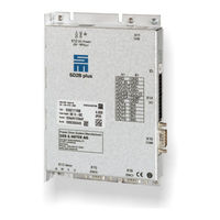
SIEB & MEYER SD2B plus Hardware Description (86 pages)
Drive Amplifiers
Brand:
SIEB & MEYER
| Category:
Amplifier
| Size: 2 MB
Table of Contents
Table of Contents
5
About this Manual
9
Illustration of Warnings
9
Illustration of General Notices
10
Abbreviations
10
General Information
11
Safety Instructions
13
Standards and Regulations
13
Working on the Device
13
Appropriate Use
14
Reasonably Foreseeable Misuse
15
Transport and Storage
15
Installation
16
Electrical Connection
17
Operation
18
Maintenance
19
Disposal
19
Legal Warranty
20
Unit Assembly Complying EMC
21
Drive Amplifier SD2B / SD2B Plus
23
Type Plate
23
Device Designation
24
Functional Overview of the Device Variants
25
Device Variant SD2B
27
Operating Instructions
27
Block Diagram
28
Dimensions/Mounting
29
Technical Data
30
Connectors
31
Device Variant SD2B Plus
33
Block Diagram
33
Dimensions/Mounting
35
Technical Data
36
Connectors
37
Connector Pin Assignment
39
Operation of the Terminal Connectors
39
Spring-Cage Connection
39
Push-In Technology
39
ID Switch
39
X2 - Motor Connection
40
X4 - DC Power Supply
40
X6 - Logic Supply
41
X9 - Inputs/Outputs
41
X10 - COM1 / Operating Terminal
42
X11 - Usb
43
X12 - DC Power Supply
43
X13 - Motor Connection
44
X14 - Inputs/Outputs / Safety Circuit (STO)
44
X15 - Encoder 0
45
X16 - Encoder 1 / Encoder Emulation
46
Connection Examples
47
X2/X13 - Motor Phases
47
X4 - Decoupling of the Main Voltage
48
X4/X6 - DC Power Supply Unit
48
X9 - Inputs/Outputs
49
Digital Inputs
49
Digital Outputs
49
Analog Input
50
X9/X14 - Temperature Sensor of the Motor
50
X10 - Bus Connection
51
Com1 - Rs232
51
CAN Bus
52
X12/X14 - DC Power Supply Unit
53
X14 - In/Out / STO
53
Digital Inputs
53
Digital Outputs
54
Analog Input
55
Safety Circuit (STO)
55
Wiring with OSSD
55
Wiring Without OSSD
56
X15, X16 - Incremental Encoder with TTL Signals
56
X16 - Enc1/Emu
57
Encoder Emulation
57
Hall Sensor 5.3
58
Pulse
58
Status Display and Error Messages
59
List of the Operating States
59
List of Drive Error Messages
60
List of Warning Messages
64
Message of the Quick Stop Functions
65
General Information Regarding the Wiring
67
Cable Requirements
67
Motor Cable
69
Electric Performance Dimensioning
71
Components
71
Output Stage
71
Power Supply
71
Motor
72
Power Consumption of a Drive
74
Safety Circuit / Restart Lock (STO)
75
Functional Description of the Restart Lock
76
Wiring Example
77
Requirements and Standards
78
Appendix
81
A Specification of Device Firmware
81
B Manufacturers
83
SIEB & MEYER Accessories
83
Connectors of the Series SD2B / SD2B Plus
83
Blocking Diode
83
Operating Terminal
83
USB>RS232/485 Converter 050201
83
Phoenix Contact
84
Index
85
Advertisement
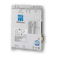
SIEB & MEYER SD2B plus Hardware Description (65 pages)
Brand:
SIEB & MEYER
| Category:
Amplifier
| Size: 4 MB
Table of Contents
Table of Contents
3
About this Manual
5
Illustration of Warnings
5
Abbreviations
5
General Information
7
Approval for the Markets in USA and Canada
7
NRTL Requirements
8
Safety Instructions
10
Standards and Regulations
10
Working on the Device
10
Appropriate Use
11
Reasonably Foreseeable Misuse
12
Transport and Storage
12
Installation
13
Electrical Connection
14
Operation
15
Maintenance
15
Disposal
16
Legal Warranty
16
Unit Assembly Complying EMC
17
Drive Amplifier SD2B Plus
18
Device Designation
18
Block Diagram
19
Type Plate
20
Functional Overview
21
Dimensions/Mounting
22
Technical Data
23
Connector Pin Assignment
24
Connectors
24
Operation of the Terminal Connectors
24
Spring-Cage Connection
24
Push-In Technology
25
ID Switch (Address Selection Switch)
25
X10 - Com1/Operating Terminal
25
X11 - USB (Parameterization)
26
X12 - DC Power Supply
26
X13 - Motor Connection
27
X14 - Inputs/Outputs / Safety Circuit (STO)
28
X15 - Encoder 0
29
X16 - Encoder 1 / Encoder Emulation
29
X26/ X27 - Servolink 4
30
Preparation of Optical Fiber Cables with Connector
30
Connection Examples
32
X10 - Bus Connection
32
COM1 - RS232 Interfaces
32
CAN Bus
33
X12/X14 - DC Power Supply Unit
34
X13 - Motor Phases
34
X14 - In/Out / STO
35
Digital Inputs
35
Digital Outputs
35
Analog Input
36
Safety Circuit (STO)
37
Wiring with OSSD
37
Wiring Without OSSD
37
X14 - Temperature Sensor of the Motor
38
X15, X16 - Incremental Encoders with TTL Signals
39
X15 - RENISHAW Biss C Mode (Unidirectional)
40
X16 - Enc1/Emu
41
Encoder Emulation
41
Hall Sensor 5.3 V
42
Pulse in
42
X26/X27 - Servolink
43
Status Display and Error Messages
44
List of the Operating States
44
List of Drive Error Messages
45
List of the Warning Messages
50
Messages of the Quick Stop Functions
51
General Information Regarding the Wiring
52
Cable Requirements
52
Motor Cable
54
Safety Circuit / Restart Lock (STO)
56
Functional Description of the Restart Lock
57
Wiring Example
58
Requirements and Standards
59
Restart Lock Procedure
60
Appendix
62
A Specification of Device Firmware
62
B Manufacturers
63
B.1 SIEB & MEYER Accessories
63
B.1.1 Connectors of the Series SD2B Plus
63
B.1.2 Operating Terminal
63
B.1.3 USB>RS232/485 Converter 050201
63
B.2 Phoenix Contact
64
Index
65
Advertisement
Related Products
SIEB & MEYER SD2B
SIEB & MEYER Drive System SD3 Series
SIEB & MEYER sinudyn-36 Series
SIEB & MEYER sinudyn-0360520 Series
SIEB & MEYER SD4B
SIEB & MEYER SD2
SIEB & MEYER SD2S
SIEB & MEYER SD2T
SIEB & MEYER SD2M
SIEB & MEYER SD2S 0362X49xy
SIEB & MEYER Categories
DC Drives
Amplifier
Gateway
Controller
Power Supply
More SIEB & MEYER Manuals
Login
Sign In
OR
Sign in with Facebook
Sign in with Google
Upload manual
Upload from disk
Upload from URL