Sign In
Upload
Manuals
Brands
SICK Manuals
Analytical Instruments
ZIRKOR Series
SICK ZIRKOR Series Manuals
Manuals and User Guides for SICK ZIRKOR Series. We have
1
SICK ZIRKOR Series manual available for free PDF download: Operating Instructions Manual
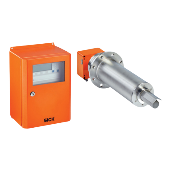
SICK ZIRKOR Series Operating Instructions Manual (88 pages)
Brand:
SICK
| Category:
Analytical Instruments
| Size: 5 MB
Table of Contents
Table of Contents
3
1 About this Document
7
Function of this Document
7
Scope of Application
7
User Qualification
7
Further Information
7
Symbols and Document Conventions
8
Warning Symbols
8
Warning Levels and Signal Words
8
Information Symbols
9
Data Integrity
9
2 For Your Safety
10
Basic Safety Information
10
Warning Information on Device
11
Intended Use
11
Purpose of the Device
11
Operation in Potentially Explosive Atmospheres
11
Responsibility of User
13
Designated Users
13
Correct Project Planning
13
Correct Use
13
Special Local Conditions
13
Read the Operating Instructions
13
3 Product Description
14
Product Identification
14
Type Plates
14
Device Versions
16
Device Variants
18
Options
18
Expansion Module
18
4 Layout and Function
19
System Overview
19
Measuring Principle
20
Scope of Application
20
Potential Hazards
20
Process Interruption
20
ATEX / Iecex Certification
21
Ignition Source Monitoring of the Probe by Means of Temperature Monitoring
21
5 Installation
22
Determination of the Requirements for Explosion Protection
22
Information on Installation in Potentially Explosive Atmospheres
22
Tools Required
23
Material Required
23
Preparing the Measuring Point
23
Transport
23
Storage Information
24
Scope of Delivery
24
Installation
24
Fitting the Counterflange on the Duct
25
Installing the Control Unit
25
Installing the Probe
26
Installing the Measuring Probe
27
Fitting the Counterflange
28
Aligning the V-Shield
29
Laying the Probe Cable and Hoses
29
Installing the Probe Cable
30
Electrical Installation
31
Accessing the Terminals
33
Instructions for the Function of the Spring-Loaded Terminal
33
Potential Equalization (PE, Ground)
34
Fitting the Ferrite Sleeves (EMC)
34
Control Unit Electrical Connections
35
Outputs/Functions and Relay Assignment
36
Digital Inputs
37
Electrical Connections on the Probe Junction Unit
37
Electrical Connection Plan - ZIRKOR Ex-D
38
Pneumatic Connections and Settings
39
Pneumatic Hose Requirements
39
Preparing the Pneumatic Hose
39
Pneumatic Connections, Probe
39
Pneumatic Connections of the Electronics
40
6 Commissioning
41
Safety Information on Commissioning
41
Initial Commissioning
42
Display - Heating Process
42
Display - Measuring Mode
42
Operating Elements and Display
43
Status Leds
43
Softkey Symbols
43
System Code
43
7 Menu Overview and Explanations
44
Sys-Menu
44
Menu Explanations
47
Measuring Ranges (Scaling)
47
Measured Value Average over [S]
47
Ma Output for System Error
47
O 2 Limit Value Alarms
48
Sensor Adjustment Values
48
Time Per Test Gas Feed
48
Stopping Time until Process (O 2 )
49
Auto. Adjustment (ACAL)
49
Settings for Auto. Adjustment
49
Remote
50
Units of Measure
50
Language
50
Changing the System Code
51
Loading the Factory Settings
51
Service (Factory Service Settings)
51
Adjustment Menu
51
Display - Adjustment
51
1-Point Adjustment (Manual)
52
2-Point Adjustment (Manual)
53
System Check
54
8 Maintenance
55
Technical Knowledge Necessary for Maintenance Work
55
Safety Instructions for Maintenance Work
55
Information on Use in Ex-Areas
56
Maintenance Plan
56
Tools Required
57
Maintenance Work
57
Replace Fuses
57
Test Air and Reference Air Volumes
58
Setting the Flow Volume (Safe Area Control Unit)
58
Setting Valves Position
60
Setting the Flow Volume (19" Rack)
60
Replacing the Filter Head
61
Replacing the Measuring Probe
62
Replacing the O 2 Measuring Cell
63
Replacing the Inner Part of the Measuring Probe
64
Stability Criteria During Adjustment
65
9 Status Messages
66
Error Messages
66
Alarm Messages
68
Maintenance Messages
68
10 Heating Shutdown in Case of Malfunction
69
General Information
69
Functional Description
70
Maintenance
70
11 Troubleshooting
71
Strongly Fluctuating O Measured Value
71
O 2 Display Remains at End of Measuring Range or Is Higher than Expected
71
Indications on the Display Are OK, Ma Output Signal Is Not Correct
71
O 2 Display on 0%, Although the Operating Mode Indicates a Higher
72
O 2 Value
72
12 Decommissioning
73
Safety Information on Decommissioning
73
Shutdown Procedure
74
Removing the Device
74
Environmentally Compatible Disposal
74
13 Technical Data
75
Dimension Drawings
75
Dimension Sheets of the Control Unit
75
Dimension Sheets of the Probes
77
Counterflange Dimensions
78
Probe Components
79
Gas Plans
81
Installation of the Electronics
82
Display Board
83
Technical Data
84
Technical Data of the Control Unit
84
Technical Data of the Measuring Probe
85
Technical Specification for the Gas Supply
85
Tightening Torques for Ex-Relevant Screw Connections
86
Advertisement
Advertisement
Related Products
SICK ZIRKOR200 Ex-G
SICK ZIRKOR200 Ex-D
SICK ZIRKOR200 Ex
SICK ZIRKOR100
SICK ZIRKOR302 P
SICK ZSE18 Series
SICK ZSE18 1 Series
SICK ZSE18 2 Series
SICK ZSE18 8 Series
SICK ZLD18
SICK Categories
Accessories
Security Sensors
Measuring Instruments
Scanner
Barcode Reader
More SICK Manuals
Login
Sign In
OR
Sign in with Facebook
Sign in with Google
Upload manual
Upload from disk
Upload from URL