Sign In
Upload
Manuals
Brands
sick Manuals
Accessories
T-EASIC FTS
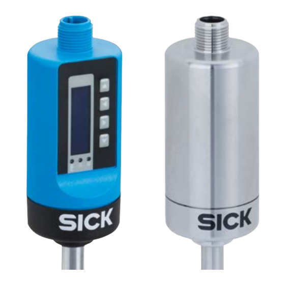
sick T-EASIC FTS Flow Sensors Manuals
Manuals and User Guides for sick T-EASIC FTS Flow Sensors. We have
3
sick T-EASIC FTS Flow Sensors manuals available for free PDF download: Operating Instructions Manual
SICK T-EASIC FTS Operating Instructions Manual (72 pages)
Flow sensor
Brand:
SICK
| Category:
Accessories
| Size: 2 MB
Table of Contents
Table of Contents
3
About this Document
6
About the Operating Instructions
6
Scope
6
Definition of the Symbols Used
6
Further Information
7
Customer Service
7
Safety Information
8
Intended Use
8
Improper Use
8
Limitation of Liability
8
Modifications and Conversions
9
Requirements on Technical and Operating Personnel
9
Operational Safety and Specific Hazards
10
Use at High Operating Temperatures
10
Basic Safety Instructions
10
Product Description
11
Product Identification
11
Information about the Housing
11
Type Code
11
Product Characteristics
12
Device View
12
Operating Buttons (Industrial Version Only)
12
Product Features and Functions
13
Principle of Operation
13
Transport and Storage
14
Transport
14
Transport Inspection
14
Storage
14
Mounting
15
Installation Conditions
15
Probe Alignment to Flow Direction
17
Probe Alignment for Empty Pipe Detection
17
Mounting the Sensor
18
Mounting the Process Connection Adapter
18
Removing the Process Connection Adapter
19
Mounting in a T-Piece
20
Electrical Installation
21
Safety
21
Notes on Electrical Installation
21
Electrical Connection
22
Overview of the Electrical Connections
22
Pin Assignment, M12 Plug Connection, 4-Pin, Version a
22
Pin Assignment, M12 Plug Connection, 4-Pin, Version B
23
Commissioning
24
Quick Commissioning (with Factory Settings)
24
Operation
24
Display, Leds and Operating Buttons (Industrial Version Only)
24
Information Shown on the Display (Industrial Version Only)
25
Leds (Industrial Version Only)
25
IO-Link
26
Measurement Configuration
26
Configuring the Measurement Mode Based on the Volume (Volume Flow and Counter) (Example)
27
Configuring the Measurement Mode Based on the "Teach Relative" Mode (Example)
27
Configuration Options for Q1 and Q2
29
Configuring the Switching Output Q1 and Q2
30
Normally Open with Configurable Hysteresis
30
Normally Closed with Configurable Hysteresis
31
Normally Open with Window Function
32
Normally Closed with Window Function
33
Configuring the Switching Output Q1 for Empty Pipe Detection
34
Configuration Of Pulse Output Q2
35
Configuring The Q2 Digital Input
36
Configuring The Q2 Analog Output
38
Advanced Menu (Advanced Settings)
39
Unit Pipe Diameter
41
Unit Velocity
41
Unit Volume Flow
41
Unit Volume
41
Unit Temperature
41
Filter (Process Data)
41
Linear Flow Factor
42
Empty Detect Factor
42
Low Flow Cutoff & Cutoff Hysteresis
43
Delay Mode Q1
44
Delay Time Q1
46
Delay Mode Q2
46
Delay Time Q2
46
Error Current Q2A
46
Display Language (Industrial Version Only)
46
Display Mode (Industrial Version Only)
47
Display Rotation (Industrial Version Only)
47
Display Lock (Industrial Version Only)
47
Simulation
47
Factory Reset
48
Password
48
Close Menu
48
Information
48
Troubleshooting
49
Error Message Shown on the Display (Industrial Version Only)
49
Outputs
51
Repair
52
Maintenance
52
Return
52
Disposal
53
Technical Data
54
Features
54
Performance
55
Mechanics/Materials
55
Ambient Conditions
55
Electrical Connections
56
Dimensional Drawings
57
Industrial Version
57
Hygienic Version
58
Industrial Version with Clamping Ring
58
Hygienic Version with Clamping Ring
59
Mounting Adapter for T-Easic ® FTS
60
G1/2 Adapter (P/N 5338774)
60
1/2" Npt Adapter (P/N 5338775)
60
M18 X 1.5 Adapter (P/N 2104208)
61
Clamp Connection with Weld End (P/N 2121340)
61
T-Pieces for T-Easic ® FTS
62
T-Piece DN25 (P/N 2118844) / DN40 (P/N 2118845) / DN50 (2118846) with Weld End
62
T-Piece DN25 (P/N 2122453) / DN40 (P/N 2122454) / DN50 (2122455) with Rp Thread
62
T-Piece DN15 (P/N 2123468) with Weld End
63
T-Piece DN15 (P/N 2123463) with Rp Thread
63
Factory Settings
64
Accessories
66
Menu Overview
67
License Text
69
Notes
70
Advertisement
SICK T-EASIC FTS Operating Instructions Manual (72 pages)
Flow sensor
Brand:
SICK
| Category:
Measuring Instruments
| Size: 5 MB
Table of Contents
Table of Contents
3
About this Document
6
Further Information
6
Symbols and Document Conventions
6
Safety Information
7
Intended Use
7
Improper Use
7
Requirements on Technical and Operating Personnel
7
Use at High Operating Temperatures
8
General Safety Notes
8
Product Description
9
Product Identification
9
Information about the Housing
9
Type Code
9
Product Characteristics
9
Device View
9
Control Elements (Industrial Version Only)
10
Product Features and Functions
10
Transport and Storage
12
Transport
12
Transport Inspection
12
Storage
12
Mounting
13
Installation Conditions
13
Probe Alignment to the Flow Direction
15
Probe Alignment for Empty Pipe Detection
16
Mounting the Sensor
16
Mounting the Process Connection Adapter
16
Removing and Remounting the Process Connection Adapter
17
Mounting in a T-Piece
18
Mounting the Hygienic Process Adapter
18
Removing the Hygienic Process Adapter
21
Cleaning the Sensor with Hygienic Process Adapter
22
Electrical Installation
23
Safety
23
Electrical Connection
23
Commissioning
25
Quick Commissioning (Using Factory Settings)
25
Operation
25
Measurement Configuration
27
Configuring the Measurement Mode Based on the Volume (Volume Flow and Counter) (Example)
28
Configuring the Measuring Mode Based on the "Teach Relative" Mode (Example)
28
Configuration Options for Q1 and Q2
29
Configuring the Q1 and Q2 Digital Output
30
Normally Open with Configurable Hysteresis
30
Normally Closed with Configurable Hysteresis
31
Normally Open with Window Function
32
Normally Closed with Window Function
33
Configuring the Digital Output Q1 for Empty Pipe Detection
33
Configuration of Pulse Output Q2
34
Configuring the Q2 Digital Input
36
Configuring the Q2 Analog Output
37
Advanced Menu (Advanced Settings)
38
Unit Pipe Diameter
39
Unit Velocity
40
Unit Volume Flow
40
Unit Volume
40
Unit Temperature
40
Filter (Process Data)
40
Linear Flow Factor
41
Empty Detect Factor
41
Low Flow Cutoff & Cutoff Hysteresis
42
Delay Mode Q1
43
Delay Time Q1
45
Delay Mode Q2
45
Delay Time Q2
46
Error Current Q2A
46
Display Language
46
Display Mode
46
Display Rotation (Industrial Version Only)
46
Display Lock (Industrial Version Only)
46
Simulation
46
Factory Reset
47
Password
47
Close Menu
47
Information
47
Troubleshooting
49
Error Message Shown on the Display (Industrial Version Only)
49
Outputs
52
Repair
53
Maintenance
53
Return
53
Disposal
54
Technical Data
55
Performance
55
Mechanics/Materials
56
Ambient Conditions
56
Electrical Connections
56
Factory Settings
57
Dimensional Drawings
59
Industrial Version
59
Hygienic Version
60
Industrial Version with Clamping Ring
61
Hygienic Version with Clamping Ring
62
Mounting Adapter for T-Easic FTS
62
G1/2 Adapter (P/N 5338774)
63
1/2" NPT Adapter (P/N 5338775)
63
M18 X 1.5 Adapter (P/N 2104208)
64
Hygienic Process Adapter DIN32676 DN25-40
64
Compression Fitting with Weld End (P/N 2121340)
65
T-Pieces for T-Easic FTS
65
T-Piece DN25 (P/N 2118844) / DN40 (P/N 2118845) / DN50 (2118846) with Weld End
65
T-Piece DN25 (P/N 2122453) / DN40 (P/N 2122454) / DN50 (2122455) with Rp Thread
66
T-Piece DN15 (P/N 2123468) with Weld End
66
T-Piece DN15 (P/N 2123463) with Rp Thread
67
Accessories
68
Menu Overview
69
Annex
71
Conformities and Certificates
71
License Text
71
sick T-EASIC FTS Operating Instructions Manual (56 pages)
Flow sensor
Brand:
sick
| Category:
Accessories
| Size: 2 MB
Table of Contents
Table of Contents
3
1 About this Document
6
Information on the Operating Instructions
6
Scope
6
Explanation of Symbols
6
Further Information
7
Customer Service
7
2 Safety Information
8
Intended Use
8
Improper Use
8
Limitation of Liability
8
Modifications and Conversions
8
Requirements for Skilled Persons and Operating Personnel
9
Operational Safety and Specific Hazards
10
Use at High Operating Temperatures
10
General Safety Notes
10
3 Product Description
11
Product Identification
11
Information on the Housing
11
Type Code
11
Product Characteristics
12
Device View
12
Operating Buttons (Industrial Version Only)
12
Product Features and Functions
13
Principle of Operation
13
Fields of Application
13
4 Transport and Storage
14
Transport
14
Transport Inspection
14
Storage
14
5 Mounting
15
Installation Conditions
15
Probe Alignment to the Flow Direction
16
Mounting the Sensor
17
Mounting the Process Connection Adapter
17
Dismounting the Process Connection Adapter
18
6 Electrical Installation
19
Safety
19
Notes on the Electrical Installation
19
Electrical Connection
20
Overview of the Electrical Connections
20
Pin Assignment, M12 Plug Connector, 4-Pin
20
7 Commissioning
21
Quick Commissioning (with Factory Settings)
21
Operation
21
Display, Leds and Operating Buttons (Industrial Version Only)
21
Information Shown on the Display (Industrial Version Only)
21
Leds (Industrial Version Only)
22
IO-Link
22
Measurement Configuration
22
Configuration of the Measurement Mode Based on Volume Absolute as Example
23
Configuration of the Measurement Mode Based on Teach Relative as Example
23
Configuration of Q1 and Q2
24
Configuration of the Switching Output Q1 and Q2
25
Normally Open with Configurable Hysteresis
25
Normally Closed with Configurable Hysteresis
26
Normally Open with Window Function
27
Normally Closed with Window Function
28
Configuration of the Digital Input Q2
29
Advanced Menu (Advanced Settings)
30
Unit Pipe Diameter
32
Unit Velocity
32
Unit Volume
32
Unit Temperature
32
Filter (Process Data)
32
Linear Flow Factor
33
Delay Mode Q1
33
Delay Time Q1
35
Delay Mode Q2
35
Delay Time Q2
36
Simulation
36
Display Mode (Industrial Version Only)
36
Factory Reset
37
Display Lock (Industrial Version Only)
37
Password
37
Advanced Menu (Close Menu)
37
Information
37
8 Troubleshooting
39
Error Message on the Display (Industrial Version Only)
39
Outputs
40
9 Repair
41
Maintenance
41
Returns
41
10 Disposal
42
11 Technical Data
43
Features
43
Performance
43
Mechanics/Materials
44
Ambient Conditions
44
Electrical Connections
45
12 Dimensional Drawings
46
Industrial Version
46
Hygenic Version
47
Mounting Adapters for T-Easic ® FTS
47
Adapter G1/2 (P/N 5338774)
47
Adapter 1/2" NPT (P/N 5338775)
48
Adapter M18 X 1.5 (P/N 2104208)
48
Adapter Clamp DIN32676 DN25-40 (P/N 2093548)
49
13 Factory Settings
50
14 Accessories
51
15 Menu Overview
52
16 License Text
54
Advertisement
Advertisement
Related Products
SICK TiM781
SICK TMM88A
SICK TMS88B
SICK TMS61B
SICK TMM61B
SICK TIM881A-2101101
SICK TriSpectorP1000
SICK TriSpectorP1008
SICK TiM8P Series
SICK TiM8 P Series
sick Categories
Accessories
Security Sensors
Measuring Instruments
Scanner
Barcode Reader
More sick Manuals
Login
Sign In
OR
Sign in with Facebook
Sign in with Google
Upload manual
Upload from disk
Upload from URL