Sign In
Upload
Manuals
Brands
SICK Manuals
Measuring Instruments
MLG-2 Prime
SICK MLG-2 Prime Automation Light Grids Manuals
Manuals and User Guides for SICK MLG-2 Prime Automation Light Grids. We have
1
SICK MLG-2 Prime Automation Light Grids manual available for free PDF download: Operating Instructions Manual
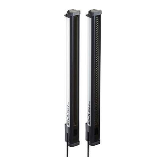
SICK MLG-2 Prime Operating Instructions Manual (62 pages)
Measuring automation light grid
Brand:
SICK
| Category:
Measuring Instruments
| Size: 3 MB
Table of Contents
Table of Contents
3
1 About this Document
6
Purpose of this Document
6
Scope
6
Target Group
6
Information Depth
6
Symbols Used
6
Abbreviations Used
7
2 Safety Information
8
Requirements for the Qualification of Personnel
8
Correct Use
8
General Safety Notes
9
3 Product Description
10
Type Labels of the MLG-2 Prime
10
Type Code of the MLG-2 Prime
10
Type Label of Sender
10
Type Label of Receiver
10
MLG-2 Prime Monitoring Height
11
Combinations of MLG-2 Prime Inputs and Outputs
11
MLG-2 Prime Sensing Range and Minimum Detectable Object Length
12
MLG-2 Prime Preconfigurations
12
MLG-2 Prime Product Properties
13
Setup and Function
13
MLG-2 Prime Device Components
14
Measurement Principle
14
MLG-2 Prime
14
MLG-2 Prime Synchronization
15
Detection Height
15
Detection Area of the MLG-2
15
Teach-In
16
Beam Blanking
16
Schematic Representation of Available Beam Separations (MM)
16
Sensing Ranges
17
Detection Area with Beams Blanked
17
Scan Time
18
Standard Scan Method
18
Scan Time in Relation to the Number of Beams
18
MLG-2 Prime Response Time and Minimum Presence Time
19
Scan Time with Cross-Beam Function
19
Beam Separation and Minimum Detectable Object
19
Minimum Detectable Object with Parallel-Beam Function
19
Cross-Beam Function
19
Minimum Detectable Object
19
Minimum Detectable Object Length
20
Minimum Detectable Object with Cross-Beam Function
20
Operating Reserve
21
Cross-Beam Function
21
Interfaces
22
Preliminary Evaluation
22
Configurable Applications of the MLG-2 Prime
22
Display and Operating Elements
22
Sender
22
Receiver
23
Leds on the Sender
23
Leds on the Front of the Receiver
23
MLG-2 Prime Control Panel with Switching Outputs
24
MLG-2 Prime Control Panel with Analog Outputs and Switching Output
24
Inputs
25
Switching Input on the MLG-2 Prime Receiver
25
Test Input on the Sender
25
Application Examples
25
Application Examples for the MLG2 Prime
25
Height Classification and Overhang Measurement
25
Position Detection on a Conveyor Belt
25
Slack Regulation
25
Access Control
25
4 Mounting
26
Scope of Delivery
26
Recommended Mounting Arrangements
26
Mounting with Light in Opposite Directions
26
Placement with Light in Opposite Directions
26
Mounting with Light in the same Direction
27
Distances When Light Is in the same Direction
27
Graph, Distances When Light Is in the same Direction
27
Minimum Distance from Reflective Surfaces
28
Mounting Procedure
28
Graph, Minimum Distance from Reflective Surfaces
28
The Sender and Receiver Are Aligned Incorrectly
28
Mounting the Quickfix Bracket
29
Mounting the Flexfix Bracket
30
Mount Quickfix Bracket to a Profile Frame
30
Mounting the Flexfix Bracket on a Profile Frame
31
Inserting the MLG-2 in the Flexfix Brackets
31
5 Electrical Installation
32
Connections of the MLG-2 Prime
32
6 Commissioning
34
Mechanical Alignment of Sender and Receiver
34
Alignment with the Quickfix Bracket
34
Alignment and Teach-In
35
MLG-2 Prime
35
Alignment with the Flexfix Bracket
35
Rotate the Receiver Once
35
Alignment Aid - Leds Alignment Quality
36
7 Operating the MLG2 Prime
37
Configuration with the Control Panel
37
Basic Operation
37
Control Panel with Leds and Membrane Keys
37
Of the MLG-2 Prime with Switching Outputs
37
MLG-2 Prime Control Panel with Analog Outputs and Switching Output
37
Control Panel
38
Setting the Application for Switching Outputs
39
Graph, Setting the Output and Application for MLG-2 Prime with Switching Outputs
39
Setting the Application for Analog Outputs and Switching Output
40
Graph, Setting the Output and Application for MLG-2 Prime with Analog Outputs and Switching Output
40
System Settings on Operating Level 2
41
Graph, System Settings on Operating Level 2
41
Measuring Functions
42
Applications for Switching Outputs
42
Example of Object Detection
42
Example of Height Classification
42
Applications for Analog Outputs
43
Example for Object Recognition
43
Example for FBB
44
Example for LBB
44
System Settings on Operating Level 2
45
Example for NBB
45
8 IO-Link
47
Configuration Via Acyclic Service Data
47
Data Storage (IO-Link)
47
Output of Process Data from the MLG-2 Prime
47
9 Servicing
48
10 Troubleshooting
49
Response to Faults
49
SICK Support
49
LED Indicators and Error Indicators
49
11 Decommissioning
50
Disposal
50
Returns
50
12 Technical Data
51
Data Sheet
51
Diagrams
53
MLG-2 Prime Response Time and Minimum Presence Time
53
Graph, MLG-2 Prime Response Time and Minimum Presence Time
53
Dimensional Drawings
54
MLG-2 Prime Dimensional Drawing
54
MLG-2 Prime (MM) Dimensional Drawing
54
Measurement Tables
55
13 Ordering Information
56
14 Accessories
57
15 Annex
59
Compliance with EU Directive
59
List of Figures
60
17 List of Tables
61
Advertisement
Advertisement
Related Products
SICK MLG-2 Pro
SICK MLG-2 ProNet
SICK MCS100E
SICK MARSIC300
SICK MARSIC200
SICK MARSIC280
SICK MERCEM300Z
SICK MOC3ZA
SICK MWS120
SICK WebChecker MLG-2
SICK Categories
Accessories
Security Sensors
Measuring Instruments
Scanner
Barcode Reader
More SICK Manuals
Login
Sign In
OR
Sign in with Facebook
Sign in with Google
Upload manual
Upload from disk
Upload from URL